PART 430 - ENERGY CONSERVATION PROGRAM FOR CONSUMER PRODUCTS
Source:
42 FR 27898, June 1, 1977, unless otherwise noted.
Subpart A - General Provisions
§ 430.1 Purpose and scope.
This part establishes the regulations for the implementation of part B of title III (42 U.S.C. 6291-6309) of the Energy Policy and Conservation Act (Pub. L. 94-163), as amended by Pub. L. 95-619, Pub. L. 100-12, Pub. L. 100-357, and Pub. L. 102-486 which establishes an energy conservation program for consumer products other than automobiles.
[62 FR 29237, May 29, 1997]
§ 430.2 Definitions.
For purposes of this part, words shall be defined as provided for in section 321 of the Act and as follows -
3-Way incandescent lamp means an incandescent lamp that -
(1) Employs two filaments, operated separately and in combination, to provide three light levels; and
(2) Is designated on the lamp packaging and marketing materials as being a 3-way incandescent lamp.
700 series fluorescent lamp means a fluorescent lamp with a color rendering index (measured according to the test procedures outlined in Appendix R to subpart B of this part) that is in the range (inclusive) of 70 to 79.
Act means the Energy Policy and Conservation Act of 1975, as amended, 42 U.S.C. 6291-6316.
Activation lock means a control mechanism (either by a physical device directly on the water heater or a control system integrated into the water heater) that is locked by default and contains a physical, software, or digital communication that must be activated with an activation key to enable to the product to operate at its designed specifications and capabilities and without which the activation of the product will provide not greater than 50 percent of the rated first hour delivery of hot water certified by the manufacturer.
Active mode means the condition in which an energy-using product -
(1) Is connected to a main power source;
(2) Has been activated; and
(3) Provides one or more main functions.
Adaptive external power supply (EPS) means an external power supply that can alter its output voltage during active-mode based on an established digital communication protocol with the end-use application without any user-generated action.
All-refrigerator means a refrigerator that does not include a compartment capable of maintaining compartment temperatures below 32 °F (0 °C) as determined according to the provisions in § 429.14(d)(2) of this chapter. It may include a compartment of 0.50 cubic-foot capacity (14.2 liters) or less for the freezing and storage of ice.
Annual fuel utilization efficiency means the efficiency descriptor for furnaces and boilers, determined using test procedures prescribed under section 323 and based on the assumption that all -
(1) Weatherized warm air furnaces or boilers are located out-of-doors;
(2) Warm air furnaces which are not weatherized are located indoors and all combustion and ventilation air is admitted through grill or ducts from the outdoors and does not communicate with air in the conditioned space;
(3) Boilers which are not weatherized are located within the heated space.
ANSI means the American National Standards Institute.
Appliance lamp means any lamp that -
(1) Is specifically designed to operate in a household appliance and has a maximum wattage of 40 watts (including an oven lamp, refrigerator lamp, and vacuum cleaner lamp); and
(2) When sold at retail, is designated and marketed for the intended application, with
(i) The designation on the lamp packaging; and
(ii) Marketing materials that identify the lamp as being for appliance use.
ASME means the American Society of Mechanical Engineers.
Automatic clothes washer means a class of clothes washer which has a control system which is capable of scheduling a preselected combination of operations, such as regulation of water temperature, regulation of the water fill level, and performance of wash, rinse, drain, and spin functions without the need for user intervention subsequent to the initiation of machine operation. Some models may require user intervention to initiate these different segments of the cycle after the machine has begun operation, but they do not require the user to intervene to regulate the water temperature by adjusting the external water faucet valves.
Back-up battery charger means a battery charger excluding UPSs:
(1) That is embedded in a separate end-use product that is designed to continuously operate using mains power (including end-use products that use external power supplies); and
(2) Whose sole purpose is to recharge a battery used to maintain continuity of power in order to provide normal or partial operation of a product in case of input power failure.
Ballast means a device used with an electric discharge lamp to obtain necessary circuit conditions (voltage, current, and waveform) for starting and operating.
Ballast efficacy factor means the relative light output divided by the power input of a fluorescent lamp ballast, as measured under test conditions specified in ANSI Standard C82.2-1984.
Ballast luminous efficiency means the total fluorescent lamp arc power divided by the fluorescent lamp ballast input power multiplied by the appropriate frequency adjustment factor, as defined in appendix Q of subpart B of this part.
Baseboard electric heater means an electric heater which is intended to be recessed in or surface mounted on walls at floor level, which is characterized by long, low physical dimensions, and which transfers heat by natural convection and/or radiation.
Basic model means all units of a given type of covered product (or class thereof) manufactured by one manufacturer; having the same primary energy source; and, which have essentially identical electrical, physical, and functional (or hydraulic) characteristics that affect energy consumption, energy efficiency, water consumption, or water efficiency; and
(1) With respect to general service fluorescent lamps, general service incandescent lamps, and incandescent reflector lamps: Lamps that have essentially identical light output and electrical characteristics - including lumens per watt (lm/W) and color rendering index (CRI).
(2) With respect to faucets and showerheads: Have the identical flow control mechanism attached to or installed within the fixture fittings, or the identical water-passage design features that use the same path of water in the highest flow mode.
(3) With respect to furnace fans: Are marketed and/or designed to be installed in the same type of installation; and
(4) With respect to central air conditioners and central air conditioning heat pumps essentially identical electrical, physical, and functional (or hydraulic) characteristics means:
(i) For split systems manufactured by outdoor unit manufacturers (OUMs): all individual combinations having the same model of outdoor unit, which means comparably performing compressor(s) [a variation of no more than five percent in displacement rate (volume per time) as rated by the compressor manufacturer, and no more than five percent in capacity and power input for the same operating conditions as rated by the compressor manufacturer], outdoor coil(s) [no more than five percent variation in face area and total fin surface area; same fin material; same tube material], and outdoor fan(s) [no more than ten percent variation in air flow and no more than twenty percent variation in power input];
(ii) For split systems having indoor units manufactured by independent coil manufacturers (ICMs): all individual combinations having comparably performing indoor coil(s) [plus or minus one square foot face area, plus or minus one fin per inch fin density, and the same fin material, tube material, number of tube rows, tube pattern, and tube size]; and
(iii) For single-package systems: all individual models having comparably performing compressor(s) [no more than five percent variation in displacement rate (volume per time) rated by the compressor manufacturer, and no more than five percent variations in capacity and power input rated by the compressor manufacturer corresponding to the same compressor rating conditions], outdoor coil(s) and indoor coil(s) [no more than five percent variation in face area and total fin surface area; same fin material; same tube material], outdoor fan(s) [no more than ten percent variation in outdoor air flow], and indoor blower(s) [no more than ten percent variation in indoor air flow, with no more than twenty percent variation in fan motor power input];
(iv) Except that,
(A) for single-package systems and single-split systems, manufacturers may instead choose to make each individual model/combination its own basic model provided the testing and represented value requirements in 10 CFR 429.16 of this chapter are met; and
(B) For multi-split, multi-circuit, and multi-head mini-split combinations, a basic model may not include both individual small-duct, high velocity (SDHV) combinations and non-SDHV combinations even when they include the same model of outdoor unit. The manufacturer may choose to identify specific individual combinations as additional basic models.
Basic-voltage external power supply means an external power supply that is not a low-voltage external power supply.
Batch means a collection of production units of a basic model from which a batch sample is selected.
Batch sample means the collection of units of the same basic model from which test units are selected.
Batch sample size means the number of units in a batch sample.
Batch size means the number of units in a batch.
Battery charger means a device that charges batteries for consumer products, including battery chargers embedded in other consumer products.
Blowout toilet means a water closet that uses a non-siphonic bowl with an integral flushing rim, a trap at the rear of the bowl, and a visible or concealed jet that operates with a blowout action.
Body spray means a shower device for spraying water onto a bather from other than the overhead position. A body spray is not a showerhead.
BPAR incandescent reflector lamp means a reflector lamp as shown in figure C78.21-278 on page 32 of ANSI C78.21-2003 (incorporated by reference; see § 430.3).
BR30 means a BR incandescent reflector lamp with a diameter of 30/8ths of an inch.
BR40 means a BR incandescent reflector lamp with a diameter of 40/8ths of an inch.
BR incandescent reflector lamp means a reflector lamp that has -
(1) A bulged section below the major diameter of the bulb and above the approximate baseline of the bulb, as shown in figure 1 (RB) on page 7 of ANSI C79.1-1994, (incorporated by reference, see § 430.3); and
(2) A finished size and shape shown in ANSI C78.21-1989 (incorporated by reference; see § 430.3), including the referenced reflective characteristics in part 7 of ANSI C78.21-1989.
BR incandescent reflector lamp means a reflector lamp that has a bulged section below the bulb's major diameter and above its approximate base line as shown in Figure 1 (RB) on page 7 of ANSI C79.1-1994. A BR30 lamp has a lamp wattage of 85 or less than 66 and a BR40 lamp has a lamp wattage of 120 or less.
Btu means British thermal unit, which is the quantity of heat required to raise the temperature of one pound of water one degree Fahrenheit.
Built-in compact cooler means any cooler with a total refrigerated volume less than 7.75 cubic feet and no more than 24 inches in depth, excluding doors, handles, and custom front panels, that is designed, intended, and marketed exclusively to be:
(1) Installed totally encased by cabinetry or panels that are attached during installation;
(2) Securely fastened to adjacent cabinetry, walls or floor;
(3) Equipped with unfinished sides that are not visible after installation; and
(4) Equipped with an integral factory-finished face or built to accept a custom front panel.
Built-in cooler means any cooler with a total refrigerated volume of 7.75 cubic feet or greater and no more than 24 inches in depth, excluding doors, handles, and custom front panels; that is designed, intended, and marketed exclusively to be:
(1) Installed totally encased by cabinetry or panels that are attached during installation;
(2) Securely fastened to adjacent cabinetry, walls or floor;
(3) Equipped with unfinished sides that are not visible after installation; and
(4) Equipped with an integral factory-finished face or built to accept a custom front panel.
Built-in refrigerator/refrigerator-freezer/freezer means any refrigerator, refrigerator-freezer or freezer with 7.75 cubic feet or greater total volume and 24 inches or less depth not including doors, handles, and custom front panels; with sides which are not finished and not designed to be visible after installation; and that is designed, intended, and marketed exclusively
(1) To be installed totally encased by cabinetry or panels that are attached during installation,
(2) to be securely fastened to adjacent cabinetry, walls or floor, and
(3) to either be equipped with an integral factory-finished face or accept a custom front panel.
Candelabra base incandescent lamp means a lamp that uses a candelabra screw base as described in ANSI C81.61, Specifications for Electric Bases, common designations E11 and E12 (incorporated by reference; see § 430.3).
Casement-only means a room air conditioner designed for mounting in a casement window with an encased assembly with a width of 14.8 inches or less and a height of 11.2 inches or less.
Casement-slider means a room air conditioner with an encased assembly designed for mounting in a sliding or casement window with a width of 15.5 inches or less.
Ceiling electric heater means an electric heater which is intended to be recessed in, surface mounted on, or hung from a ceiling, and which transfers heat by radiation and/or convection (either natural or forced).
Ceiling fan means a nonportable device that is suspended from a ceiling for circulating air via the rotation of fan blades. For all other ceiling fan-related definitions, see appendix U to this subpart.
Ceiling fan light kit means equipment designed to provide light from a ceiling fan that can be -
(1) Integral, such that the equipment is attached to the ceiling fan prior to the time of retail sale; or
(2) Attachable, such that at the time of retail sale the equipment is not physically attached to the ceiling fan, but may be included inside the ceiling fan at the time of sale or sold separately for subsequent attachment to the fan.
Central air conditioner or central air conditioning heat pump means a product, other than a packaged terminal air conditioner or packaged terminal heat pump, which is powered by single phase electric current, air cooled, rated below 65,000 Btu per hour, not contained within the same cabinet as a furnace, the rated capacity of which is above 225,000 Btu per hour, and is a heat pump or a cooling unit only. A central air conditioner or central air conditioning heat pump may consist of: A single-package unit; an outdoor unit and one or more indoor units; an indoor unit only; or an outdoor unit with no match. In the case of an indoor unit only or an outdoor unit with no match, the unit must be tested and rated as a system (combination of both an indoor and an outdoor unit). For all central air conditioner and central air conditioning heat pump-related definitions, see appendix M or M1 of subpart B of this part.
Central system humidifier means a class of humidifier designed to add moisture into the air stream of a heating system.
Class A external power supply -
(1) Means a device that -
(i) Is designed to convert line voltage AC input into lower voltage AC or DC output;
(ii) Is able to convert to only one AC or DC output voltage at a time;
(iii) Is sold with, or intended to be used with, a separate end-use product that constitutes the primary load;
(iv) Is contained in a separate physical enclosure from the end-use product;
(v) Is connected to the end-use product via a removable or hard-wired male/female electrical connection, cable, cord, or other wiring; and
(vi) Has nameplate output power that is less than or equal to 250 watts;
(2) But, does not include any device that -
(i) Requires Federal Food and Drug Administration listing and approval as a medical device in accordance with section 513 of the Federal Food, Drug, and Cosmetic Act (21 U.S.C. 360(c)); or
(ii) Powers the charger of a detachable battery pack or charges the battery of a product that is fully or primarily motor operated.
Clothes washer means a consumer product designed to clean clothes, utilizing a water solution of soap and/or detergent and mechanical agitation or other movement, and must be one of the following classes: automatic clothes washers, semi-automatic clothes washers, and other clothes washers.
Cold temperature fluorescent lamp means a fluorescent lamp specifically designed to start at −20 °F when used with a ballast conforming to the requirements of ANSI C78.81 (incorporated by reference; see § 430.3) and ANSI C78.901 (incorporated by reference; see § 430.3), and is expressly designated as a cold temperature lamp both in markings on the lamp and in marketing materials, including catalogs, sales literature, and promotional material.
Colored fluorescent lamp means a fluorescent lamp designated and marketed as a colored lamp and not designed or marketed for general illumination applications with either of the following characteristics:
(1) A CRI less than 40, as determined according to the method set forth in CIE Publication 13.3 (incorporated by reference; see § 430.3); or
(2) A correlated color temperature less than 2,500K or greater than 7,000K as determined according to the method set forth in IES LM-9 (incorporated by reference; see § 430.3).
Colored incandescent lamp means an incandescent lamp designated and marketed as a colored lamp that has -
(1) A color rendering index of less than 50, as determined according to the test method given in CIE 13.3 (incorporated by reference; see § 430.3); or
(2) A correlated color temperature of less than 2,500K, or greater than 4,600K, where correlated temperature is computed according to the “Computation of Correlated Color Temperature and Distribution Temperature,” Journal of the Optical Society of America, (incorporated by reference; see § 430.3).
Color Rendering Index or CRI means the measured degree of color shift objects undergo when illuminated by a light source as compared with the color of those same objects when illuminated by a reference source of comparable color temperature.
Combination cooler refrigeration product means any cooler-refrigerator, cooler-refrigerator-freezer, or cooler-freezer.
Compact fluorescent lamp (CFL) means an integrated or non-integrated single-base, low-pressure mercury, electric-discharge source in which a fluorescing coating transforms some of the ultraviolet energy generated by the mercury discharge into light; the term does not include circline or U-shaped lamps.
Compact refrigerator/refrigerator-freezer/freezer means any refrigerator, refrigerator-freezer or freezer with a total refrigerated volume of less than 7.75 cubic feet (220 liters). (Total refrigerated volume shall be determined using the applicable test procedure appendix prescribed in subpart B of this part.)
Component video means a video display interface as defined in the Consumer Electronics Association's (CEA) standard, CEA-770.3-D (incorporated by reference; see § 430.3).
Composite video means a video display interface that uses Radio Corporation of America (RCA) connections carrying a signal defined by the Society of Motion Picture and Television Engineers' (SMPTE) standard, SMPTE 170M-2004 (incorporated by reference; see § 430.3) for regions that support a power frequency of 59.94 Hz or International Telecommunication Union's (ITU) standard, ITU-R BT 470-6 (incorporated by reference; see § 430.3) for regions that support a power frequency of 50 Hz.
Consumer product means any article (other than an automobile, as defined in Section 501(1) of the Motor Vehicle Information and Cost Savings Act):
(1) Of a type -
(i) Which in operation consumes, or is designed to consume, energy or, with respect to showerheads, faucets, water closets, and urinals, water; and
(ii) Which, to any significant extent, is distributed in commerce for personal use or consumption by individuals;
(2) Without regard to whether such article of such type is in fact distributed in commerce for personal use or consumption by an individual, except that such term includes fluorescent lamp ballasts, general service fluorescent lamps, incandescent reflector lamps, showerheads, faucets, water closets, and urinals distributed in commerce for personal or commercial use or consumption.
Consumer refrigeration product means a refrigerator, refrigerator-freezer, freezer, or miscellaneous refrigeration product.
Contractor means a person (other than the manufacturer or distributor) who sells to and/or installs for an end user a central air conditioner subject to regional standards. The term “end user” means the entity that purchases or selects for purchase the central air conditioner. Some examples of typical “end users” are homeowners, building owners, building managers, and property developers.
Controlling parameter means a measurable quantity or an algorithm (such as temperature or usage pattern) used for inferring heating load to a residential boiler, which would then result in incremental changes in boiler supply water temperature.
Convection microwave oven means a microwave oven that incorporates convection features and any other means of cooking in a single compartment.
Conventional cooking top means a category of cooking products which is a household cooking appliance consisting of a horizontal surface containing one or more surface units that utilize a gas flame, electric resistance heating, or electric inductive heating. This includes any conventional cooking top component of a combined cooking product.
Conventional oven means a category of cooking products which is a household cooking appliance consisting of one or more compartments intended for the cooking or heating of food by means of either a gas flame or electric resistance heating. It does not include portable or countertop ovens which use electric resistance heating for the cooking or heating of food and are designed for an electrical supply of approximately 120 volts. This includes any conventional oven(s) component of a combined cooking product.
Convertible cooking appliance means any kitchen range and oven which is a household cooking appliance designed by the manufacturer to be changed in service from use with natural gas to use with LP-gas, and vice versa, by incorporating in the appliance convertible orifices for the main gas burners and a convertible gas pressure regulator.
Cooking products means consumer products that are used as the major household cooking appliances. They are designed to cook or heat different types of food by one or more of the following sources of heat: Gas, electricity, or microwave energy. Each product may consist of a horizontal cooking top containing one or more surface units and/or one or more heating compartments.
Cooler means a cabinet, used with one or more doors, that has a source of refrigeration capable of operating on single-phase, alternating current and is capable of maintaining compartment temperatures either:
(1) No lower than 39 °F (3.9 °C); or
(2) In a range that extends no lower than 37 °F (2.8 °C) but at least as high as 60 °F (15.6 °C) as determined according to the applicable provisions in § 429.61(d)(2) of this chapter.
Cooler-all-refrigerator means a cooler-refrigerator that does not include a compartment capable of maintaining compartment temperatures below 32 °F (0 °C) as determined according to the provisions in § 429.61(d)(2) of this chapter. It may include a compartment of 0.50 cubic-foot capacity (14.2 liters) or less for the freezing and storage of ice.
Cooler-freezer means a cabinet, used with one or more doors, that has a source of refrigeration that requires single-phase, alternating current electric energy input only, and consists of two or more compartments, including at least one cooler compartment as defined in appendix A of subpart B of this part, where the remaining compartment(s) are capable of maintaining compartment temperatures at 0 °F (−17.8 °C) or below as determined according to the provisions in § 429.61(d)(2) of this chapter.
Cooler-refrigerator means a cabinet, used with one or more doors, that has a source of refrigeration that requires single-phase, alternating current electric energy input only, and consists of two or more compartments, including at least one cooler compartment as defined in appendix A of subpart B of this part, where:
(1) At least one of the remaining compartments is not a cooler compartment as defined in appendix A of subpart B of this part and is capable of maintaining compartment temperatures above 32 °F (0 °C) and below 39 °F (3.9 °C) as determined according to § 429.61(d)(2) of this chapter;
(2) The cabinet may also include a compartment capable of maintaining compartment temperatures below 32 °F (0 °C) as determined according to § 429.61(d)(2) of this chapter; but
(3) The cabinet does not provide a separate low temperature compartment capable of maintaining compartment temperatures below 8 °F (−13.3 °C) as determined according to § 429.61(d)(2) of this chapter.
Cooler-refrigerator-freezer means a cabinet, used with one or more doors, that has a source of refrigeration that requires single-phase, alternating current electric energy input only, and consists of three or more compartments, including at least one cooler compartment as defined in appendix A of subpart B of this part, where:
(1) At least one of the remaining compartments is not a cooler compartment as defined in appendix A of subpart B of this part and is capable of maintaining compartment temperatures above 32 °F (0 °C) and below 39 °F (3.9 °C) as determined according to § 429.61(d)(2) of this chapter; and
(2) At least one other compartment is capable of maintaining compartment temperatures below 8 °F (−13.3 °C) and may be adjusted by the user to a temperature of 0 °F (−17.8 °C) or below as determined according to § 429.61(d)(2) of this chapter.
Covered product means a consumer product -
(1) Of a type specified in section 322 of the Act; or
(2) That is a ceiling fan, ceiling fan light kit, medium base compact fluorescent lamp, dehumidifier, battery charger, external power supply, torchiere, portable air conditioner, or miscellaneous refrigeration product.
Dealer means a type of contractor, generally with a relationship with one or more specific manufacturers.
Dehumidifier means a product, other than a portable air conditioner, room air conditioner, or packaged terminal air conditioner, that is a self-contained, electrically operated, and mechanically encased assembly consisting of -
(1) A refrigerated surface (evaporator) that condenses moisture from the atmosphere;
(2) A refrigerating system, including an electric motor;
(3) An air-circulating fan; and
(4) A means for collecting or disposing of the condensate.
Design voltage with respect to an incandescent lamp means:
(1) The voltage marked as the intended operating voltage;
(2) The mid-point of the voltage range if the lamp is marked with a voltage range; or
(3) 120 V if the lamp is not marked with a voltage or voltage range.
Designed and marketed means that the intended application of the lamp or ballast is clearly stated in all publicly available documents (e.g., product literature, catalogs, and packaging labels). This definition is applicable to terms related to the following covered lighting products: Fluorescent lamp ballasts; fluorescent lamps; general service fluorescent lamps; general service incandescent lamps; general service lamps; incandescent lamps; incandescent reflector lamps; medium base compact fluorescent lamps; and specialty application mercury vapor lamp ballasts.
Detachable battery means a battery that is -
(1) Contained in a separate enclosure from the product; and
(2) Intended to be removed or disconnected from the product for recharging.
Direct heating equipment means vented home heating equipment and unvented home heating equipment.
Direct operation external power supply means an external power supply that can operate a consumer product that is not a battery charger without the assistance of a battery.
Direct vent system means a system supplied by a manufacturer which provides outdoor air or air from an unheated space (such as an attic or crawl space) directly to a furnace or vented heater for combustion and for draft relief if the unit is equipped with a draft control device.
Dishwasher means a cabinet-like appliance which with the aid of water and detergent, washes, rinses, and dries (when a drying process is included) dishware, glassware, eating utensils, and most cooking utensils by chemical, mechanical and/or electrical means and discharges to the plumbing drainage system.
Distributor means a person (other than a manufacturer or retailer) to whom a consumer appliance product is delivered or sold for purposes of distribution in commerce.
DOE means the Department of Energy.
Dual-duct portable air conditioner means a portable air conditioner that draws some or all of the condenser inlet air from outside the conditioned space through a duct attached to an adjustable window bracket, may draw additional condenser inlet air from the conditioned space, and discharges the condenser outlet air outside the conditioned space by means of a separate duct attached to an adjustable window bracket.
Dual-flush water closet means a water closet incorporating a feature that allows the user to flush the water closet with either a reduced or a full volume of water.
Electric boiler means an electrically powered furnace designed to supply low pressure steam or hot water for space heating application. A low pressure steam boiler operates at or below 15 pounds per square inch gauge (psig) steam pressure; a hot water boiler operates at or below 160 psig water pressure and 250 °F. water temperature.
Electric central furnace means a furnace designed to supply heat through a system of ducts with air as the heating medium, in which heat is generated by one or more electric resistance heating elements and the heated air is circulated by means of a fan or blower.
Electric clothes dryer means a cabinet-like appliance designed to dry fabrics in a tumble-type drum with forced air circulation. The heat source is electricity and the drum and blower(s) are driven by an electric motor(s).
Electric heater means an electric appliance in which heat is generated from electrical energy and dissipated by convection and radiation and includes baseboard electric heaters, ceiling electric heaters, floor electric heaters, portable electric heaters, and wall electric heaters.
Electric instantaneous water heater means a water heater that uses electricity as the energy source, has a nameplate input rating of 12 kW or less, and contains no more than one gallon of water per 4,000 Btu per hour of input.
Electric storage water heater means a water heater that uses electricity as the energy source, has a nameplate input rating of 12 kW or less, and contains more than one gallon of water per 4,000 Btu per hour of input.
Electromechanical hydraulic toilet means any water closet that utilizes electrically operated devices, such as, but not limited to, air compressors, pumps, solenoids, motors, or macerators in place of or to aid gravity in evacuating waste from the toilet bowl.
Electronic ballast means a device that uses semiconductors as the primary means to control lamp starting and operation.
Energy conservation standard means any standards meeting the definitions of that term in 42 U.S.C. 6291(6) and 42 U.S.C. 6311(18) as well as any other water conservation standards and design requirements found in this part or parts 430 or 431.
Energy use of a type of consumer product which is used by households means the energy consumed by such product within housing units occupied by households (such as energy for space heating and cooling, water heating, the operation of appliances, or other activities of the households), and includes energy consumed on any property that is contiguous with a housing unit and that is used primarily by the household occupying the housing unit (such as energy for exterior lights or heating a pool).
ER incandescent reflector lamp means a reflector lamp that has -
(1) An elliptical section below the major diameter of the bulb and above the approximate baseline of the bulb, as shown in figure 1 (RE) on page 7 of ANSI C79.1-1994, (incorporated by reference; see § 430.3); and
(2) A finished size and shape shown in ANSI C78.21-1989, (incorporated by reference; see § 430.3).
ER30 means an ER incandescent reflector lamp with a diameter of 30/8ths of an inch.
ER40 means an ER incandescent reflector lamp with a diameter of 40/8ths of an inch.
Estimated annual operating cost means the aggregate retail cost of the energy which is likely to be consumed annually, and in the case of showerheads, faucets, water closets, and urinals, the aggregate retail cost of water and wastewater treatment services likely to be incurred annually, in representative use of a consumer product, determined in accordance with Section 323 of EPCA (42 U.S.C. 6293).
External power supply means an external power supply circuit that is used to convert household electric current into DC current or lower-voltage AC current to operate a consumer product. However, the term does not include a power supply circuit, driver, or device that is designed exclusively to be connected to, and power -
(1) Light-emitting diodes providing illumination;
(2) Organic light-emitting diodes providing illumination; or
(3) Ceiling fans using direct current motors.
External power supply design family means a set of external power supply basic models, produced by the same manufacturer, which share the same circuit layout, output power, and output cord resistance, but differ in output voltage.
Faucet means a lavatory faucet, kitchen faucet, metering faucet, or replacement aerator for a lavatory or kitchen faucet.
Fitting means a device that controls and guides the flow of water.
Floor electric heater means an electric heater which is intended to be recessed in a floor, and which transfers by radiation and/or convection (either natural or forced).
Fluorescent lamp means a low pressure mercury electric-discharge source in which a fluorescing coating transforms some of the ultraviolet energy generated by the mercury discharge into light, including only the following:
(1) Any straight-shaped lamp (commonly referred to as 4-foot medium bipin lamps) with medium bipin bases of nominal overall length of 48 inches and rated wattage of 25 or more;
(2) Any U-shaped lamp (commonly referred to as 2-foot U-shaped lamps) with medium bipin bases of nominal overall length between 22 and 25 inches and rated wattage of 25 or more;
(3) Any rapid start lamp (commonly referred to as 8-foot high output lamps) with recessed double contact bases of nominal overall length of 96 inches;
(4) Any instant start lamp (commonly referred to as 8-foot slimline lamps) with single pin bases of nominal overall length of 96 inches and rated wattage of 49 or more;
(5) Any straight-shaped lamp (commonly referred to as 4-foot miniature bipin standard output lamps) with miniature bipin bases of nominal overall length between 45 and 48 inches and rated wattage of 25 or more; and
(6) Any straight-shaped lamp (commonly referred to 4-foot miniature bipin high output lamps) with miniature bipin bases of nominal overall length between 45 and 48 inches and rated wattage of 44 or more.
Fluorescent lamp ballast means a device which is used to start and operate fluorescent lamps by providing a starting voltage and current and limiting the current during normal operation.
Fluorescent lamp designed for use in reprographic equipment means a fluorescent lamp intended for use in equipment used to reproduce, reprint, or copy graphic material.
Flushometer tank means a device whose function is defined in flushometer valve, but integrated within an accumulator vessel affixed and adjacent to the fixture inlet so as to cause an effective enlargement of the supply line immediately before the unit.
Flushometer valve means a valve attached to a pressurized water supply pipe and so designed that when actuated, it opens the line for direct flow into the fixture at a rate and quantity to properly operate the fixture, and then gradually closes to provide trap reseal in the fixture in order to avoid water hammer. The pipe to which this device is connected is in itself of sufficient size, that when open, will allow the device to deliver water at a sufficient rate of flow for flushing purposes.
Forced air central furnace means a gas or oil burning furnace designed to supply heat through a system of ducts with air as the heating medium. The heat generated by combustion of gas or oil is transferred to the air within a casing by conduction through heat exchange surfaces and is circulated through the duct system by means of a fan or blower.
Freestanding compact cooler means any cooler, excluding built-in compact coolers, with a total refrigerated volume less than 7.75 cubic feet.
Freestanding cooler means any cooler, excluding built-in coolers, with a total refrigerated volume of 7.75 cubic feet or greater.
Freezer means a cabinet, used with one or more doors, that has a source of refrigeration that requires single-phase, alternating current electric energy input only and is capable of maintaining compartment temperatures of 0 °F (−17.8 °C) or below as determined according to the provisions in § 429.14(d)(2) of this chapter. It does not include any refrigerated cabinet that consists solely of an automatic ice maker and an ice storage bin arranged so that operation of the automatic icemaker fills the bin to its capacity. However, the term does not include:
(1) Any product that does not include a compressor and condenser unit as an integral part of the cabinet assembly; or
(2) Any miscellaneous refrigeration product that must comply with an applicable miscellaneous refrigeration product energy conservation standard.
Furnace means a product which utilizes only single-phase electric current, or single-phase electric current or DC current in conjunction with natural gas, propane, or home heating oil, and which -
(1) Is designed to be the principal heating source for the living space of a residence;
(2) Is not contained within the same cabinet with a central air conditioner whose rated cooling capacity is above 65,000 Btu per hour;
(3) Is an electric central furnace, electric boiler, forced-air central furnace, gravity central furnace, or low-pressure steam or hot water boiler; and
(4) Has a heat input rate of less than 300,000 Btu per hour for electric boilers and low-pressure steam or hot water boilers and less than 225,000 Btu per hour for forced-air central furnaces, gravity central furnaces, and electric central furnaces.
Furnace fan means an electrically-powered device used in a consumer product for the purpose of circulating air through ductwork.
Gas means either natural gas or propane.
Gas clothes dryer means a cabinet-like appliance designed to dry fabrics in a tumble-type drum with forced air circulation. The heat source is gas and the drum and blower(s) are driven by an electric motor(s).
Gas-fired instantaneous water heater means a water heater that uses gas as the main energy source, has a nameplate input rating less than 200,000 Btu/h, and contains no more than one gallon of water per 4,000 Btu per hour of input.
Gas-fired storage water heater means a water heater that uses gas as the main energy source, has a nameplate input rating of 75,000 Btu/h or less, and contains more than one gallon of water per 4,000 Btu per hour of input.
General lighting application means lighting that provides an interior or exterior area with overall illumination.
General service fluorescent lamp means any fluorescent lamp which can be used to satisfy the majority of fluorescent lighting applications, but does not include any lamp designed and marketed for the following nongeneral application:
(1) Fluorescent lamps designed to promote plant growth;
(2) Fluorescent lamps specifically designed for cold temperature applications;
(3) Colored fluorescent lamps;
(4) Impact-resistant fluorescent lamps;
(5) Reflectorized or aperture lamps;
(6) Fluorescent lamps designed for use in reprographic equipment;
(7) Lamps primarily designed to produce radiation in the ultra-violet region of the spectrum; and
(8) Lamps with a Color Rendering Index of 87 or greater.
General service incandescent lamp means a standard incandescent or halogen type lamp that is intended for general service applications; has a medium screw base; has a lumen range of not less than 310 lumens and not more than 2,600 lumens or, in the case of a modified spectrum lamp, not less than 232 lumens and not more than 1,950 lumens; and is capable of being operated at a voltage range at least partially within 110 and 130 volts; however this definition does not apply to the following incandescent lamps -
(1) An appliance lamp;
(2) A black light lamp;
(3) A bug lamp;
(4) A colored lamp;
(5) An infrared lamp;
(6) A left-hand thread lamp;
(7) A marine lamp;
(8) A marine signal service lamp;
(9) A mine service lamp;
(10) A plant light lamp;
(11) A reflector lamp;
(12) A rough service lamp;
(13) A shatter-resistant lamp (including a shatter-proof lamp and a shatter-protected lamp);
(14) A sign service lamp;
(15) A silver bowl lamp;
(16) A showcase lamp;
(17) A 3-way incandescent lamp;
(18) A traffic signal lamp;
(19) A vibration service lamp;
(20) A G shape lamp (as defined in ANSI C78.20) (incorporated by reference; see § 430.3) and ANSI C79.1-2002 (incorporated by reference; see § 430.3) with a diameter of 5 inches or more;
General service lamp includes general service incandescent lamps, compact fluorescent lamps, general service light-emitting diode lamps, organic light-emitting diode lamps, and any other lamps that the Secretary determines are used to satisfy lighting applications traditionally served by general service incandescent lamps; however, this definition does not apply to any lighting application or bulb shape excluded from the “general service incandescent lamp” definition, or any general service fluorescent lamp or incandescent reflector lamp.
Gravity central furnace means a gas fueled furnace which depends primarily on natural convection for circulation of heated air and which is designed to be used in conjunction with a system of ducts.
Grid-enabled water heater means an electric resistance water heater that -
(1) Has a rated storage tank volume of more than 75 gallons;
(2) Is manufactured on or after April 16, 2015;
(3) Is equipped at the point of manufacture with an activation lock and;
(4) Bears a permanent label applied by the manufacturer that -
(i) Is made of material not adversely affected by water;
(ii) Is attached by means of non-water-soluble adhesive; and
(iii) Advises purchasers and end-users of the intended and appropriate use of the product with the following notice printed in 16.5 point Arial Narrow Bold font: “IMPORTANT INFORMATION: This water heater is intended only for use as part of an electric thermal storage or demand response program. It will not provide adequate hot water unless enrolled in such a program and activated by your utility company or another program operator. Confirm the availability of a program in your local area before purchasing or installing this product.”
Hand-held showerhead means a showerhead that can be held or fixed in place for the purpose of spraying water onto a bather and that is connected to a flexible hose.
High-definition multimedia interface or HDMI® means an audio and video interface as defined by HDMI® Specification Informational Version 1.0 or greater (incorporated by reference; see § 430.3).
Home heating equipment, not including furnaces means vented home heating equipment and unvented home heating equipment.
Household means an entity consisting of either an individual, a family, or a group of unrelated individuals, who reside in a particular housing unit. For the purpose of this definition:
(1) Group quarters means living quarters that are occupied by an institutional group of 10 or more unrelated persons, such as a nursing home, military barracks, halfway house, college dormitory, fraternity or sorority house, convent, shelter, jail or correctional institution.
(2) Housing unit means a house, an apartment, a group of rooms, or a single room occupied as separate living quarters, but does not include group quarters.
(3) Separate living quarters means living quarters:
(i) To which the occupants have access either:
(A) Directly from outside of the building, or
(B) Through a common hall that is accessible to other living quarters and that does not go through someone else's living quarters, and
(ii) Occupied by one or more persons who live and eat separately from occupant(s) of other living quarters, if any, in the same building.
Immersed heating element means an electrically powered heating device which is designed to operate while totally immersed in water in such a manner that the heat generated by the device is imparted directly to the water.
Impact-resistant fluorescent lamp means a lamp that:
(1) Has a coating or equivalent technology that is compliant with NSF/ANSI 51 (incorporated by reference; see § 430.3) and is designed to contain the glass if the glass envelope of the lamp is broken; and
(2) Is designated and marketed for the intended application, with:
(i) The designation on the lamp packaging; and
(ii) Marketing materials that identify the lamp as being impact-resistant, shatter-resistant, shatter-proof, or shatter-protected.
Import means to import into the customs territory of the United States.
Incandescent lamp means a lamp in which light is produced by a filament heated to incandescence by an electric current, including only the following:
(1) Any lamp (commonly referred to as lower wattage non-reflector general service lamps, including any tungsten halogen lamp) that has a rated wattage between 30 and 199, has an E26 medium screw base, has a rated voltage or voltage range that lies at least partially in the range of 115 and 130 volts, and is not a reflector lamp.
(2) Any incandescent reflector lamp.
(3) Any general service incandescent lamp (commonly referred to as a high-or higher-wattage lamp) that has a rated wattage above 199 (above 205 for a high wattage reflector lamp).
Incandescent reflector lamp (commonly referred to as a reflector lamp) means any lamp in which light is produced by a filament heated to incandescence by an electric current, which: contains an inner reflective coating on the outer bulb to direct the light; is not colored; is not designed for rough or vibration service applications; is not an R20 short lamp; has an R, PAR, ER, BR, BPAR, or similar bulb shapes with an E26 medium screw base; has a rated voltage or voltage range that lies at least partially in the range of 115 and 130 volts; has a diameter that exceeds 2.25 inches; and has a rated wattage that is 40 watts or higher.
Indirect operation external power supply means an external power supply that cannot operate a consumer product that is not a battery charger without the assistance of a battery as determined by the steps in paragraphs (1)(i) through (v) of this definition:
(1) If the external power supply (EPS) can be connected to an end-use consumer product and that consumer product can be operated using battery power, the method for determining whether that EPS is incapable of operating that consumer product directly is as follows:
(i) If the end-use product has a removable battery, remove it for the remainder of the test and proceed to the step in paragraph (1)(v) of this definition. If not, proceed to the step in paragraph (1)(ii).
(ii) Charge the battery in the application via the EPS such that the application can operate as intended before taking any additional steps.
(iii) Disconnect the EPS from the application. From an off mode state, turn on the application and record the time necessary for it to become operational to the nearest five second increment (5 sec, 10 sec, etc.).
(iv) Operate the application using power only from the battery until the application stops functioning due to the battery discharging.
(v) Connect the EPS first to mains and then to the application. Immediately attempt to operate the application. If the battery was removed for testing and the end-use product operates as intended, the EPS is not an indirect operation EPS and paragraph 2 of this definition does not apply. If the battery could not be removed for testing, record the time for the application to become operational to the nearest five second increment (5 seconds, 10 seconds, etc.).
(2) If the time recorded in paragraph (1)(v) of this definition is greater than the summation of the time recorded in paragraph (1)(iii) of this definition and five seconds, the EPS cannot operate the application directly and is an indirect operation EPS.
Installation of a central air conditioner means the connection of the refrigerant lines and/or electrical systems to make the central air conditioner operational.
Integrated light-emitting diode lamp means an integrated LED lamp as defined in ANSI/IES RP-16 (incorporated by reference; see § 430.3).
Intermediate base incandescent lamp means a lamp that uses an intermediate screw base as described in ANSI C81.61, Specifications for Electric Bases, common designation E17 (incorporated by reference; see § 430.3).
Kerosene means No. 1 fuel oil with a viscosity meeting the specifications as specified in UL-730-1974, section 36.9 and in tables 2 and 3 of ANSI Standard Z91.1-1972.
Lamp Efficacy (LE) means the measured lumen output of a lamp in lumens divided by the measured lamp electrical power input in watts expressed in units of lumens per watt (LPW).
Lamps primarily designed to produce radiation in the ultraviolet region of the spectrum means fluorescent lamps that primarily emit light in the portion of the electromagnetic spectrum where light has a wavelength between 10 and 400 nanometers.
Lifetime of a compact fluorescent lamp means the length of operating time between first use and failure of 50 percent of the sample units (as specified in § 429.35(a)(1) of this chapter), determined in accordance with the test procedures described in section 3.3 of appendix W to subpart B of this part.
Lifetime of an integrated light-emitting diode lamp means the length of operating time between first use and failure of 50 percent of the sample units (as required by § 429.56(a)(1) of this chapter), when measured in accordance with the test procedures described in section 4 of appendix BB to subpart B of this part.
Light-emitting diode or LED means a p-n junction solid state device of which the radiated output, either in the infrared region, the visible region, or the ultraviolet region, is a function of the physical construction, material used, and exciting current of the device.
Low consumption has the meaning given such a term in ASME A112.19.2-2008. (see § 430.3)
Low pressure steam or hot water boiler means an electric, gas or oil burning furnace designed to supply low pressure steam or hot water for space heating application. A low pressure steam boiler operates at or below 15 pounds psig steam pressure; a hot water boiler operates at or below 160 psig water pressure and 250 °F. water temperature.
Low-voltage external power supply means an external power supply with a nameplate output voltage less than 6 volts and nameplate output current greater than or equal to 550 milliamps.
LP-gas means liquified petroleum gas, and includes propane, butane, and propane/butane mixtures.
Major cooking component means either a conventional cooking top, a conventional oven or a microwave oven.
Manufacture means to manufacture, produce, assemble, or import.
Manufacturer means any person who manufactures a consumer product.
Medium base compact fluorescent lamp means an integrally ballasted fluorescent lamp with a medium screw base, a rated input voltage range of 115 to 130 volts and which is designed as a direct replacement for a general service incandescent lamp; however, the term does not include -
(1) Any lamp that is -
(i) Specifically designed to be used for special purpose applications; and
(ii) Unlikely to be used in general purpose applications, such as the applications described in the definition of “General Service Incandescent Lamp” in this section; or
(2) Any lamp not described in the definition of “General Service Incandescent Lamp” in this section that is excluded by the Secretary, by rule, because the lamp is -
(i) Designed for special applications; and
(ii) Unlikely to be used in general purpose applications.
Medium screw base means an Edison screw base identified with the prefix E-26 in the “American National Standard for Electric Lamp Bases”, ANSI_IEC C81.61-2003, published by the American National Standards Institute.
Microwave oven means a category of cooking products which is a household cooking appliance consisting of a compartment designed to cook or heat food by means of microwave energy, including microwave ovens with or without thermal elements designed for surface browning of food and convection microwave ovens. This includes any microwave oven(s) component of a combined cooking product.
Miscellaneous refrigeration product means a consumer refrigeration product other than a refrigerator, refrigerator-freezer, or freezer, which includes coolers and combination cooler refrigeration products.
Mobile home furnace means a direct vent furnace that is designed for use only in mobile homes.
Modified spectrum means, with respect to an incandescent lamp, an incandescent lamp that -
(1) Is not a colored incandescent lamp; and
(2) When operated at the rated voltage and wattage of the incandescent lamp -
(A) Has a color point with (x,y) chromaticity coordinates on the C.I.E. 1931 chromaticity diagram, figure 2, page 3 of IESNA LM-16 (incorporated by reference; see § 430.3) that lies below the black-body locus; and
(B) Has a color point with (x,y) chromaticity coordinates on the C.I.E. 1931 chromaticity diagram, figure 2, page 3 of IESNA LM-16 (incorporated by reference; see § 430.3) that lies at least 4 MacAdam steps, as referenced in IESNA LM-16, distant from the color point of a clear lamp with the same filament and bulb shape, operated at the same rated voltage and wattage.
Natural gas means natural gas as defined by the Federal Power Commission.
Off mode means the condition in which an energy using product -
(1) Is connected to a main power source; and
(2) Is not providing any stand-by or active mode function.
Oil means heating oil grade No. 2 as defined in American Society for Testing and Materials (ASTM) D396-71.
Oil-fired instantaneous water heater means a water heater that uses oil as the main energy source, has a nameplate input rating of 210,000 Btu/h or less, and contains no more than one gallon of water per 4,000 Btu per hour of input.
Oil-fired storage water heater means a water heater that uses oil as the main energy source, has a nameplate input rating of 105,000 Btu/h or less, and contains more than one gallon of water per 4,000 Btu per hour of input.
Organic light-emitting diode or OLED means a thin-film light-emitting device that typically consists of a series of organic layers between 2 electrical contacts (electrodes).
Other clothes washer means a class of clothes washer which is not an automatic or semi-automatic clothes washer.
Other cooking products means any category of cooking products other than conventional cooking tops, conventional ovens, and microwave ovens.
Outdoor furnace or boiler is a furnace or boiler normally intended for installation out-of-doors or in an unheated space (such as an attic or a crawl space).
Packaged terminal air conditioner means a wall sleeve and a separate unencased combination of heating and cooling assemblies specified by the builder and intended for mounting through the wall. It includes a prime source of refrigeration, separable outdoor louvers, forced ventilation, and heating availability energy.
Packaged terminal heat pump means a packaged terminal air conditioner that utilizes reverse cycle refrigeration as its prime heat source and should have supplementary heating availability by builder's choice of energy.
Person includes any individual, corporation, company, association, firm, partnership, society, trust, joint venture or joint stock company, the government, and any agency of the United States or any State or political subdivision thereof.
Pin-based means
(1) the base of a fluorescent lamp, that is not integrally ballasted and that has a plug-in lamp base, including multi-tube, multibend, spiral, and circline types, or
(2) a socket that holds such a lamp.
Pool heater means an appliance designed for heating nonpotable water contained at atmospheric pressure, including heating water in swimming pools, spas, hot tubs and similar applications.
Portable air conditioner means a portable encased assembly, other than a “packaged terminal air conditioner,” “room air conditioner,” or “dehumidifier,” that delivers cooled, conditioned air to an enclosed space, and is powered by single-phase electric current. It includes a source of refrigeration and may include additional means for air circulation and heating.
Portable dehumidifier means a dehumidifier designed to operate within the dehumidified space without the attachment of additional ducting, although means may be provided for optional duct attachment.
Portable electric heater means an electric heater which is intended to stand unsupported, and can be moved from place to place within a structure. It is connected to electric supply by means of a cord and plug, and transfers heat by radiation and/or convention (either natural or forced).
Primary heater means a heating device that is the principal source of heat for a structure and includes baseboard electric heaters, ceiling electric heaters, and wall electric heaters.
Private labeler means an owner of a brand or trademark on the label of a consumer product which bears a private label. A consumer product bears a private label if:
(1) Such product (or its container) is labeled with the brand or trademark of a person other than a manufacturer of such product;
(2) The person with whose brand or trademark such product (or container) is labeled has authorized or caused such product to be so labeled; and
(3) The brand or trademark of a manufacturer of such product does not appear on such label.
Propane means a hydrocarbon whose chemical composition is predominantly C3H8, whether recovered from natural gas or crude oil.
R20 incandescent reflector lamp means a reflector lamp that has a face diameter of approximately 2.5 inches, as shown in figure 1(R) on page 7 of ANSI C79.1-1994 (incorporated by reference; see § 430.3).
R20 short lamp means a lamp that is an R20 incandescent reflector lamp that has a rated wattage of 100 watts; has a maximum overall length of 3 and 5/8, or 3.625, inches; and is designed, labeled, and marketed specifically for pool and spa applications.
Rated lifetime for general service incandescent lamps means the length of operating time of a sample of lamps (as defined in § 429.27(a)(2)(iv) of this chapter) between first use and failure of 50 percent of the sample size in accordance with test procedures described in IESNA LM-49 (incorporated by reference; see § 430.3), as determined in section 4.2 of Appendix R of this subpart. The operating time is based on the middle lamp operating time for an odd number of samples and the average operating time of the two middle lamps for an even number of samples.
Rated voltage with respect to incandescent lamps means:
(1) The design voltage if the design voltage is 115 V, 130 V or between 115V and 130 V:
(2) 115 V if the design voltage is less than 115 V and greater than or equal to 100 V and the lamp can operate at 115 V; and
(3) 130 V if the design voltage is greater than 130 V and less than or equal to 150 V and the lamp can operate at 130 V.
Rated wattage means:
(1) With respect to fluorescent lamps and general service fluorescent lamps:
(i) If the lamp is listed in ANSI C78.81 (incorporated by reference; see § 430.3) or ANSI C78.901 (incorporated by reference; see § 430.3), the rated wattage of a lamp determined by the lamp designation of Clause 11.1 of ANSI C78.81 or ANSI C78.901;
(ii) If the lamp is a residential straight-shaped lamp, and not listed in ANSI C78.81 (incorporated by reference; see § 430.3), the wattage of a lamp when operated on a reference ballast for which the lamp is designed; or
(iii) If the lamp is neither listed in one of the ANSI standards referenced in (1)(i) of this definition, nor a residential straight-shaped lamp, the electrical power of a lamp when measured according to the test procedures outlined in appendix R to subpart B of this part.
(2) With respect to general service incandescent lamps and incandescent reflector lamps, the electrical power measured according to the test procedures outlined in appendix R to subpart B of this part.
Reflectorized or aperture lamp means a fluorescent lamp that contains an inner reflective coating on the bulb to direct light.
Refrigerant-desiccant dehumidifier means a whole-home dehumidifier that removes moisture from the process air by means of a desiccant material in addition to a refrigeration system.
Refrigerator means a cabinet, used with one or more doors, that has a source of refrigeration that requires single-phase, alternating current electric energy input only and is capable of maintaining compartment temperatures above 32 °F (0 °C) and below 39 °F (3.9 °C) as determined according to § 429.14(d)(2) of this chapter. A refrigerator may include a compartment capable of maintaining compartment temperatures below 32 °F (0 °C), but does not provide a separate low temperature compartment capable of maintaining compartment temperatures below 8 °F (−13.3 °C) as determined according to § 429.14(d)(2). However, the term does not include:
(1) Any product that does not include a compressor and condenser unit as an integral part of the cabinet assembly;
(2) A cooler; or
(3) Any miscellaneous refrigeration product that must comply with an applicable miscellaneous refrigeration product energy conservation standard.
Refrigerator-freezer means a cabinet, used with one or more doors, that has a source of refrigeration that requires single-phase, alternating current electric energy input only and consists of two or more compartments where at least one of the compartments is capable of maintaining compartment temperatures above 32 °F (0 °C) and below 39 °F (3.9 °C) as determined according to § 429.14(d)(2) of this chapter, and at least one other compartment is capable of maintaining compartment temperatures of 8 °F (−13.3 °C) and may be adjusted by the user to a temperature of 0 °F (−17.8 °C) or below as determined according to § 429.14(d)(2). However, the term does not include:
(1) Any product that does not include a compressor and condenser unit as an integral part of the cabinet assembly; or
(2) Any miscellaneous refrigeration product that must comply with an applicable miscellaneous refrigeration product energy conservation standard.
Replacement ballast means a ballast that -
(1) Is designed for use to replace an existing fluorescent lamp ballast in a previously installed luminaire;
(2) Is marked “FOR REPLACEMENT USE ONLY”;
(3) Is shipped by the manufacturer in packages containing not more than 10 fluorescent lamp ballasts; and
(4) Has output leads that when fully extended are a total length that is less than the length of the lamp with which the ballast is intended to be operated.
Residential straight-shaped lamp means a low pressure mercury electric-discharge source in which a fluorescing coating transforms some of the ultraviolet energy generated by the mercury discharge into light, including a straight-shaped fluorescent lamp with medium bi-pin bases of nominal overall length of 48 inches and is either designed exclusively for residential applications; or designed primarily and marketed exclusively for residential applications.
(1) A lamp is designed exclusively for residential applications if it will not function for more than 100 hours with a commercial high-power-factor ballast.
(2) A lamp is designed primarily and marketed exclusively for residential applications if it:
(i) Is permanently and clearly marked as being for residential use only;
(ii) Has a life of 6,000 hours or less when used with a commercial high-power-factor ballast;
(iii) Is not labeled or represented as a replacement for a fluorescent lamp that is a covered product; and
(iv) Is marketed and distributed in a manner designed to minimize use of the lamp with commercial high-power-factor ballasts.
(3) A manufacturer may market and distribute a lamp in a manner designed to minimize use of the lamp with commercial high-power-factor ballasts by:
(i) Packaging and labeling the lamp in a manner that clearly indicates the lamp is for residential use only and includes appropriate instructions concerning proper and improper use; if the lamp is included in a catalog or price list that also includes commercial/industrial lamps, listing the lamp in a separate residential section accompanied by notes about proper use on the same page; and providing as part of any express warranty accompanying the lamp that improper use voids such warranty; or
(ii) Using other comparably effective measures to minimize use with commercial high-power-factor ballasts.
Room air conditioner means a window-mounted or through-the-wall-mounted encased assembly, other than a “packaged terminal air conditioner,” that delivers cooled, conditioned air to an enclosed space, and is powered by single-phase electric current. It includes a source of refrigeration and may include additional means for ventilating and heating.
Rough or vibration service incandescent reflector lamp means a reflector lamp: in which a C-11 (5 support), C-17 (8 support), or C-22 (16 support) filament is mounted (the number of support excludes lead wires); in which the filament configuration is as shown in Chapter 6 of the 1993 Illuminating Engineering Society of North America Lighting Handbook, 8th Edition (see 10 CFR 430.22); and that is designated and marketed specifically for rough or vibration service applications.
Rough service lamp means a lamp that -
(1) Has a minimum of 5 supports with filament configurations that are C-7A, C-11, C-17, and C-22 as listed in Figure 6-12 of the IESNA Lighting Handbook (incorporated by reference; see § 430.3), or similar configurations where lead wires are not counted as supports; and
(2) Is designated and marketed specifically for ‘rough service’ applications, with
(i) The designation appearing on the lamp packaging; and
(ii) Marketing materials that identify the lamp as being for rough service.
S-video means a video display interface that transmits analog video over two channels: luma and chroma as defined by IEC 60933-5 Ed. 1.0 (incorporated by reference; see § 430.3).
Safety shower showerhead means a showerhead designed to meet the requirements of ISEA Z358.1 (incorporated by reference, see § 430.3).
Secretary means the Secretary of the Department of Energy.
Security or life safety alarm or surveillance system means:
(1) Equipment designed and marketed to perform any of the following functions (on a continuous basis):
(i) Monitor, detect, record, or provide notification of intrusion or access to real property or physical assets or notification of threats to life safety.
(ii) Deter or control access to real property or physical assets, or prevent the unauthorized removal of physical assets.
(iii) Monitor, detect, record, or provide notification of fire, gas, smoke, flooding, or other physical threats to real property, physical assets, or life safety.
(2) This term does not include any product with a principal function other than life safety, security, or surveillance that:
(i) Is designed and marketed with a built-in alarm or theft-deterrent feature; or
(ii) Does not operate necessarily and continuously in active mode.
Semi-automatic clothes washer means a class of clothes washer that is the same as an automatic clothes washer except that user intervention is required to regulate the water temperature by adjusting the external water faucet valves.
Shatter-resistant lamp, shatter-proof lamp, or shatter-protected lamp means a lamp that -
(1) Has a coating or equivalent technology that is compliant with NSF/ANSI 51 (incorporated by reference; see § 430.3) and is designed to contain the glass if the glass envelope of the lamp is broken; and
(2) Is designated and marketed for the intended application, with
(i) The designation on the lamp packaging; and
(ii) Marketing materials that identify the lamp as being shatter-resistant, shatter-proof, or shatter-protected.
Showerhead means any showerhead (including a handheld showerhead) other than a safety showerhead. DOE interprets the term “showerhead” to mean an accessory to a supply fitting for spraying water onto a bather, typically from an overhead position.
Single-duct portable air conditioner means a portable air conditioner that draws all of the condenser inlet air from the conditioned space without the means of a duct, and discharges the condenser outlet air outside the conditioned space through a single duct attached to an adjustable window bracket.
Small-duct high-velocity (SDHV) electric furnace means an electric furnace that:
(1) Is designed for, and produces, at least 1.2 inches of external static pressure when operated at the certified air volume rate of 220-350 CFM per rated ton of cooling in the highest default cooling airflow-control setting; and
(2) When applied in the field, uses high velocity room outlets generally greater than 1,000 fpm that have less than 6.0 square inches of free area.
Small-duct high-velocity (SDHV) modular blower means a modular blower that:
(1) Is designed for, and produces, at least 1.2 inches of external static pressure when operated at the certified air volume rate of 220-350 CFM per rated ton of cooling in the highest default cooling airflow-controls setting; and
(2) When applied in the field, uses high velocity room outlets generally greater than 1,000 fpm that have less than 6.0 square inches of free area.
Space constrained product means a central air conditioner or heat pump:
(1) That has rated cooling capacities no greater than 30,000 BTU/hr;
(2) That has an outdoor or indoor unit having at least two overall exterior dimensions or an overall displacement that:
(i) Is substantially smaller than those of other units that are:
(A) Currently usually installed in site-built single family homes; and
(B) Of a similar cooling, and, if a heat pump, heating capacity; and
(ii) If increased, would certainly result in a considerable increase in the usual cost of installation or would certainly result in a significant loss in the utility of the product to the consumer; and
(3) Of a product type that was available for purchase in the United States as of December 1, 2000.
Specialty application mercury vapor lamp ballast means a mercury vapor lamp ballast that -
(1) Is designed and marketed for operation of mercury vapor lamps used in quality inspection, industrial processing, or scientific use, including fluorescent microscopy and ultraviolet curing; and
(2) In the case of a specialty application mercury vapor lamp ballast, the label of which -
(i) Provides that the specialty application mercury vapor lamp ballast is ‘For specialty applications only, not for general illumination’; and
(ii) Specifies the specific applications for which the ballast is designed.
Standby mode means the condition in which an energy-using product -
(1) Is connected to a main power source; and
(2) Offers one or more of the following user-oriented or protective functions:
(i) To facilitate the activation or deactivation of other functions (including active mode) by remote switch (including remote control), internal sensor, or timer; or
(ii) Continuous functions, including information or status displays (including clocks) or sensor-based functions.
State means a State, the District of Columbia, Puerto Rico, or any territory or possession of the United States.
State regulation means a law or regulation of a State or political subdivision thereof.
Supplementary heater means a heating device that provides heat to a space in addition to that which is supplied by a primary heater. Supplementary heaters include portable electric heaters.
Surface unit means either a heating unit mounted in a cooking top, or a heating source and its associated heated area of the cooking top, on which vessels are placed for the cooking or heating of food.
Television set or TV means a product designed to produce dynamic video, contains an internal TV tuner encased within the product housing, and that is capable of receiving dynamic visual content from wired or wireless sources including but not limited to:
(1) Broadcast and similar services for terrestrial, cable, satellite, and/or broadband transmission of analog and/or digital signals; and/or
(2) Display-specific data connections, such as HDMI, Component video, S-video, Composite video; and/or
(3) Media storage devices such as a USB flash drive, memory card, or a DVD; and/or
(4) Network connections, usually using Internet Protocol, typically carried over Ethernet or Wi-Fi.
Through-the-wall central air conditioner means a central air conditioner that is designed to be installed totally or partially within a fixed-size opening in an exterior wall, and:
(1) Is not weatherized;
(2) Is clearly and permanently marked for installation only through an exterior wall;
(3) Has a rated cooling capacity no greater than 30,000 Btu/hr;
(4) Exchanges all of its outdoor air across a single surface of the equipment cabinet; and
(5) Has a combined outdoor air exchange area of less than 800 square inches (split systems) or less than 1,210 square inches (single packaged systems) as measured on the surface described in paragraph (4) of this definition.
Through-the-wall central air conditioning heat pump means a heat pump that is designed to be installed totally or partially within a fixed-size opening in an exterior wall, and:
(1) Is not weatherized;
(2) Is clearly and permanently marked for installation only through an exterior wall;
(3) Has a rated cooling capacity no greater than 30,000 Btu/hr;
(4) Exchanges all of its outdoor air across a single surface of the equipment cabinet; and
(5) Has a combined outdoor air exchange area of less than 800 square inches (split systems) or less than 1,210 square inches (single packaged systems) as measured on the surface described in paragraph (4) of this definition.
Torchiere means a portable electric lamp with a reflector bowl that directs light upward to give indirect illumination.
Unvented gas heater means an unvented, self-contained, free-standing, nonrecessed gas-burning appliance which furnishes warm air by gravity or fan circulation.
Unvented home heating equipment means a class of home heating equipment, not including furnaces, used for the purpose of furnishing heat to a space proximate to such heater directly from the heater and without duct connections and includes electric heaters and unvented gas and oil heaters.
Unvented oil heater means an unvented, self-contained, free-standing, nonrecessed oil-burning appliance which furnishes warm air by gravity or fan circulation.
Urinal means a plumbing fixture which receives only liquid body waste and, on demand, conveys the waste through a trap seal into a gravity drainage system, except such term does not include fixtures designed for installations in prisons.
Vented floor furnace means a self-contained vented heater suspended from the floor of the space being heated, taking air for combustion from outside this space. The vented floor furnace supplies heated air circulated by gravity or by a fan directly into the space to be heated through openings in the casing.
Vented home heating equipment or vented heater means a class of home heating equipment, not including furnaces, designed to furnish warmed air to the living space of a residence, directly from the device, without duct connections (except that boots not to exceed 10 inches beyond the casing may be permitted) and includes: vented wall furnace, vented floor furnace, and vented room heater.
Vented room heater means a self-contained, free standing, nonrecessed, vented heater for furnishing warmed air to the space in which it is installed. The vented room heater supplies heated air circulated by gravity or by a fan directly into the space to be heated through openings in the casing.
Vented wall furnace means a self-contained vented heater complete with grilles or the equivalent, designed for incorporation in, or permanent attachment to, a wall of a residence and furnishing heated air circulated by gravity or by a fan directly into the space to be heated through openings in the casing.
Vibration service lamp means a lamp that -
(1) Has filament configurations that are C-5, C-7A, or C-9, as listed in Figure 6-12 of the IESNA Lighting Handbook (incorporated by reference; see § 430.3) or similar configurations;
(2) Has a maximum wattage of 60 watts;
(3) Is sold at retail in packages of 2 lamps or less; and
(4) Is designated and marketed specifically for vibration service or vibration-resistant applications, with -
(i) The designation appearing on the lamp packaging; and
(ii) Marketing materials that identify the lamp as being vibration service only.
Voltage range means a band of operating voltages as marked on an incandescent lamp, indicating that the lamp is designed to operate at any voltage within the band.
Wall electric heater means an electric heater (excluding baseboard electric heaters) which is intended to be recessed in or surface mounted on walls, which transfers heat by radiation and/or convection (either natural or forced) and which includes forced convectors, natural convectors, radiant heaters, high wall or valance heaters.
Water closet means a plumbing fixture that has a water-containing receptor which receives liquid and solid body waste, and upon actuation, conveys the waste through an exposed integral trap seal into a gravity drainage system, except such term does not include fixtures designed for installation in prisons.
Water heater means a product which utilizes oil, gas, or electricity to heat potable water for use outside the heater upon demand, including -
(1) Storage type units which heat and store water at a thermostatically controlled temperature, including gas storage water heaters with an input of 75,000 Btu per hour or less, oil storage water heaters with an input of 105,000 Btu per hour or less, and electric storage water heaters with an input of 12 kilowatts or less;
(2) Instantaneous type units which heat water but contain no more than one gallon of water per 4,000 Btu per hour of input, including gas instantaneous water heaters with an input of 200,000 Btu per hour or less, oil instantaneous water heaters with an input of 210,000 Btu per hour or less, and electric instantaneous water heaters with an input of 12 kilowatts or less; and
(3) Heat pump type units, with a maximum current rating of 24 amperes at a voltage no greater than 250 volts, which are products designed to transfer thermal energy from one temperature level to a higher temperature level for the purpose of heating water, including all ancillary equipment such as fans, storage tanks, pumps, or controls necessary for the device to perform its function.
Water use means the quantity of water flowing through a showerhead, faucet, water closet, or urinal at point of use, determined in accordance with test procedures under appendices S and T of subpart B of this part.
Weatherized warm air furnace or boiler means a furnace or boiler designed for installation outdoors, approved for resistance to wind, rain, and snow, and supplied with its own venting system.
Whole-home dehumidifier means a dehumidifier designed to be installed with ducting to deliver return process air to its inlet and to supply dehumidified process air from its outlet to one or more locations in the dehumidified space.
[42 FR 27898, June 1, 1977]
§ 430.3 Materials incorporated by reference.
(a) Certain material is incorporated by reference into this subpart with the approval of the Director of the Federal Register in accordance with 5 U.S.C. 552(a) and 1 CFR part 51. To enforce any edition other than that specified in this section, DOE must publish a document in the Federal Register and the material must be available to the public. All approved material is available for inspection at the U.S. Department of Energy, Office of Energy Efficiency and Renewable Energy, Building Technologies Program, Sixth Floor, 950 L'Enfant Plaza SW, Washington, DC 20024, (202) 586-2945, https://www.energy.gov/eere/buildings/appliance-and-equipment-standards-program, and may be obtained from the other sources in this section. It is also available for inspection at the National Archives and Records Administration (NARA). For information on the availability of this material at NARA, email: fedreg.legal@nara.gov, or go to: www.archives.gov/federal-register/cfr/ibr-locations.html.
(b) Air Movement and Control Association International, Inc. (AMCA), 30 West University Drive, Arlington Heights, IL 60004, (847) 394-0150, or by going to http://www.amca.org/store/item.aspx?ItemId=81.
(1) ANSI/ASHRAE 51-07/ANSI/AMCA 210-07 (“ANSI/AMCA 210”), Laboratory Methods of Testing Fans for Certified Aerodynamic Performance Rating, AMCA approved July 28, 2006; IBR approved for appendix X1 to subpart B.
(2) ANSI/AMCA Standard 208-18, (“AMCA 208-18”), Calculation of the Fan Energy Index, ANSI approved January 24, 2018, IBR approved for appendix U to this subpart.
(3) ANSI/AMCA 210-07, ANSI/ASHRAE 51-07 (“AMCA 210-2007”), Laboratory Methods of Testing Fans for Certified Aerodynamic Performance Rating, ANSI approved August 17, 2007, Section 8 - Report and Results of Test, Section 8.2 - Performance graphical representation of test results, IBR approved for appendices M and M1 to subpart B, as follows:
(i) Figure 2A - Static Pressure Tap, and
(ii) Figure 12 - Outlet Chamber Setup - Multiple Nozzles in Chamber.
(4) ANSI/AMCA Standard 230-15 (“AMCA 230-15”), “Laboratory Methods of Testing Air Circulating Fans for Rating and Certification,” ANSI approved October 16, 2015, IBR approved for appendix U to this subpart, as follows:
(i) Section 3 - Units of Measurement;
(ii) Section 4 - Symbols and Subscripts; (including Table 1 - Symbols and Subscripts);
(iii) Section 5 - Definitions (except 5.1);
(iv) Section 6 - Instruments and Section Methods of Measurement;
(v) Section 7 - Equipment and Setups (except the last 2 bulleted items in 7.1 - Allowable test setups);
(vi) Section 8 - Observations and Conduct of Test;
(vii) Section 9 - Calculations (except 9.5); and
(viii) Test Figure 1 - Vertical Airflow Setup with Load Cell (Ceiling Fans).
(c) AHRI. Air-Conditioning, Heating, and Refrigeration Institute, 2111 Wilson Blvd, Suite 500, Arlington, VA 22201, 703-524-8800, or go to http://www.ahrinet.org.
(1) ANSI/AHRI 210/240-2008 with Addenda 1 and 2 (”AHRI 210/240-2008”), 2008 Standard for Performance Rating of Unitary Air-Conditioning & Air-Source Heat Pump Equipment, ANSI approved October 27, 2011 (Addendum 1 dated June 2011 and Addendum 2 dated March 2012), IBR approved for appendices M and M1 to subpart B, as follows:
(i) Section 6 - Rating Requirements, Section 6.1 - Standard Ratings, 6.1.3 - Standard Rating Tests, 6.1.3.2 - Electrical Conditions;
(ii) Section 6 - Rating Requirements, Section 6.1 - Standard Ratings, 6.1.3 - Standard Rating Tests, 6.1.3.4 - Outdoor-Coil Airflow Rate;
(iii) Section 6 - Rating Requirements, Section 6.1 - Standard Ratings, 6.1.3 - Standard Rating Tests, 6.1.3.5 - Requirements for Separated Assemblies;
(iv) Figure D1 - Tunnel Air Enthalpy Test Method Arrangement;
(v) Figure D2 - Loop Air Enthalpy Test Method Arrangement; and
(vi) Figure D4 - Room Air Enthalpy Test Method Arrangement.
(2) AHRI Standard 1160-2009 (“AHRI 1160”), Performance Rating of Heat Pump Pool Heaters, 2009, IBR approved for appendix P to subpart B.
(3) ANSI/AHRI 1230-2010 with Addendum 2 (“AHRI 1230-2010”), 2010 Standard for Performance Rating of Variable Refrigerant Flow (VRF) Multi-Split Air-Conditioning and Heat Pump Equipment (including Addendum 1 dated March 2011), ANSI approved August 2, 2010 (Addendum 2 dated June 2014), IBR approved for appendices M and M1 to subpart B, as follows:
(i) Section 3 - Definitions (except 3.8, 3.9, 3.13, 3.14, 3.15, 3.16, 3.23, 3.24, 3.26, 3.27, 3.28, 3.29, 3.30, and 3.31);
(ii) Section 5 - Test Requirements, Section 5.1 (untitled), 5.1.3-5.1.4;
(iii) Section 6 - Rating Requirements, Section 6.1 - Standard Ratings, 6.1.5 - Airflow Requirements for Systems with Capacities <65,000 Btu/h [19,000 W];
(iv) Section 6 - Rating Requirements, Section 6.1 - Standard Ratings, 6.1.6 - Outdoor-Coil Airflow Rate (Applies to all Air-to-Air Systems);
(v) Section 6 - Rating Requirements, Section 6.2 - Conditions for Standard Rating Test for Air-cooled Systems < 65,000 Btu/h [19,000W] (except Table 8); and
(vi) Table 4 - Refrigerant Line Length Correction Factors.
(d) AATCC. American Association of Textile Chemists and Colorists, P.O. Box 12215, Research Triangle Park, NC 27709, (919) 549-3526, or go to www.aatcc.org.
(1) AATCC Test Method 79-2010, Absorbency of Textiles, Revised 2010, IBR approved for Appendix J2 to Subpart B.
(2) AATCC Test Method 118-2007, Oil Repellency: Hydrocarbon Resistance Test, Revised 2007, IBR approved for Appendix J2 to Subpart B.
(3) AATCC Test Method 135-2010, Dimensional Changes of Fabrics after Home Laundering, Revised 2010, IBR approved for Appendix J2 to Subpart B.
(e) ANSI. American National Standards Institute, 25 W. 43rd Street, 4th Floor, New York, NY 10036, 212-642-4900, or go to http://www.ansi.org.
(1) ANSI C78.3-1991 (“ANSI C78.3”), American National Standard for Fluorescent Lamps-Instant-start and Cold-Cathode Types-Dimensional and Electrical Characteristics, approved July 15, 1991; IBR approved for § 430.32.
(2) ANSI C78.20-2003, Revision of ANSI C78.20-1995 (“ANSI C78.20”), American National Standard for electric lamps - A, G, PS, and Similar Shapes with E26 Medium Screw Bases, approved October 30, 2003; IBR approved for § 430.2.
(3) ANSI C78.21-1989, American National Standard for Electric Lamps - PAR and R Shapes, approved March 3, 1989, IBR approved for § 430.2.
(4) ANSI C78.21-2003, Revision of ANSI C78.21-1995 with all supplements, American National Standard for Electric Lamps - PAR and R Shapes, approved October 30, 2003, IBR approved for § 430.2.
(5) ANSI_ANSLG C78.81-2010, (“ANSI C78.81”), American National Standard for Electric Lamps - Double-Capped Fluorescent Lamps - Dimensional and Electrical Characteristics, approved January 14, 2010, IBR approved for §§ 430.2 and 430.32 and appendix R to subpart B.
(6) ANSI C78.81-2016, (“ANSI C78.81-2016”), American National Standard for Electric Lamps - Double-Capped Fluorescent Lamps - Dimensional and Electrical Characteristics, approved June 29, 2016, IBR approved for appendix Q to subpart B.
(7) ANSI C78.375-1997, Revision of ANSI C78.375-1991 (“ANSI C78.375”), American National Standard for Fluorescent Lamps - Guide for Electrical Measurements, first edition, approved September 25, 1997; IBR approved for appendix R to subpart B.
(8) ANSI C78.375A-2014, (“ANSI C78.375A”), American National Standard for Electric Lamps - Fluorescent Lamps - Guide for Electrical Measures, approved August 28, 2014, IBR approved for appendix Q to subpart B.
(9) ANSI_IEC C78.901-2005, Revision of ANSI C78.901-2001 (“ANSI C78.901”), American National Standard for Electric Lamps - Single-Based Fluorescent Lamps - Dimensional and Electrical Characteristics, approved March 23, 2005; IBR approved for § 430.2 and appendix R to subpart B.
(10) ANSI C78.901-2014, American National Standard for Electric Lamps - Single-Based Fluorescent Lamps - Dimensional and Electrical Characteristics, ANSI approved July 2, 2014; IBR approved for appendix W to subpart B.
(11) ANSI/NEMA C78.901-2016 (“ANSI C78.901-2016”), American National Standard for Electric Lamps - Single-Based Fluorescent Lamps - Dimensional and Electrical Characteristics, ANSI approved August 23, 2016, IBR approved for appendix Q to subpart B.
(12) ANSI C79.1-1994, American National Standard for Nomenclature for Glass Bulbs - Intended for Use with Electric Lamps, approved March 24, 1994, IBR approved for § 430.2.
(13) ANSI C79.1-2002, American National Standard for Electric Lamps - Nomenclature for Glass Bulbs Intended for Use with Electric Lamps, approved September 16, 2002, IBR approved for § 430.2.
(14) ANSI_ANSLG_ C81.61-2006, Revision of ANSI C81.61-2005, (“ANSI C81.61”), American National Standard for electrical lamp bases - Specifications for Bases (Caps) for Electric Lamps, approved August 25, 2006, IBR approved for § 430.2.
(15) ANSI C82.1-2004 (R2008, R2015), (“ANSI C82.1”), American National Standard for Lamp Ballasts - Line Frequency Fluorescent Lamp Ballasts, approved November 20, 2015; IBR approved for appendix Q to subpart B.
(16) ANSI C82.2-2002 (R2007, R2016), (“ANSI C82.2”), American National Standard for Lamp Ballasts - Method of Measurement of Fluorescent Lamp Ballasts, approved July 12, 2016, IBR approved for appendix Q to subpart B.
(17) ANSI C82.3-2002, Revision of ANSI C82.3-1983 (R 1995) (“ANSI C82.3”), American National Standard for Reference Ballasts for Fluorescent Lamps, approved September 4, 2002; IBR approved for appendix R to subpart B.
(18) ANSI C82.3-2016, (“ANSI C82.3”), American National Standard for Reference Ballasts for Fluorescent Lamps, approved April 8, 2016; IBR approved for appendix Q to subpart B.
(19) ANSI/NEMA C82.11-2017, (“ANSI C82.11”), American National Standard for Lamp Ballasts - High-Frequency Fluorescent Lamp Ballasts, approved January 23, 2017; IBR approved for appendix Q to subpart B.
(20) ANSI C82.13-2002 (“ANSI C82.13”), American National Standard for Lamp Ballasts - Definitions for Fluorescent Lamps and Ballasts, approved July 23, 2002; IBR approved for appendix Q to subpart B.
(21) ANSI C82.77-2002, (“ANSI C82.77”) Harmonic Emission Limits - Related Power Quality Requirements for Lighting Equipment, approved January 17, 2002; IBR approved for appendix Q to subpart B.
(22) ANSI/NEMA WD 6-2016, Wiring Devices - Dimensional Specifications, ANSI approved February 11, 2016, IBR approved for Appendix Y to subpart B; as follows:
(i) Figure 1-15 - Plug and Receptacle; and
(ii) Figure 5-15 - Plug and Receptacle.
(23) ANSI Z21.56-2006, section 2.10 (“ANSI Z21.56”), Standard for Gas-Fired Pool Heaters, approved December 13, 2005, IBR approved for appendix P to subpart B.
(24) ANSI Z21.50-2007 (CSA 2.22-2007), (“ANSI Z21.50”), Vented Gas Fireplaces, Fifth Edition, Approved February 22, 2007, IBR approved for § 430.2.
(25) ANSI Z21.86-2008, (“ANSI Z21.86”), Vented Gas-Fired Space Heating Appliances, Fifth Edition, approved March 28, 2008, IBR approved for appendix O to subpart B.
(26) ANSI Z21.88-2009 (CSA 2.33-2009), (“ANSI Z21.88”), Vented Gas Fireplace Heaters, Fifth Edition, Approved March 26, 2009, IBR approved for § 430.2.
The standards referenced in paragraphs (e)(6), (8), (11), (15), (16), (18), (19), and (21) of this section were all published by National Electrical Manufacturers Association (NEMA) and are also available from National Electrical Manufacturers Association, 1300 North 17th Street, Suite 900, Rosslyn, Virginia 22209, https://www.nema.org/Standards/Pages/default.aspx.
(f) AS/NZS. Australian/New Zealand Standard, GPO Box 476, Sydney NSW 2001, (02) 9237-6000 or (12) 0065-4646, or go to www.standards.org.au/Standards New Zealand, Level 10 Radio New Zealand House 144 The Terrace Wellington 6001 (Private Bag 2439 Wellington 6020), (04) 498-5990 or (04) 498-5991, or go to www.standards.co.nz.
(1) AS/NZS 4474.1:2007, Performance of Household Electrical Appliances - Refrigerating Appliances; Part 1: Energy Consumption and Performance, Second edition, published August 15, 2007, IBR approved for Appendix A to Subpart B.
(2) [Reserved]
(g) ASHRAE. American Society of Heating, Refrigerating and Air-Conditioning Engineers, Inc., Publication Sales, 1791 Tullie Circle, NE., Atlanta, GA 30329, 800-527-4723 or 404-636-8400, or go to http://www.ashrae.org.
(1) ANSI/ASHRAE Standard 16-2016 (“ANSI/ASHRAE 16”), Method of Testing for Rating Room Air Conditioners, Packaged Terminal Air Conditioners, and Packaged Terminal Heat Pumps for Cooling and Heating Capacity, ANSI approved November 1, 2016, IBR approved for appendix F to subpart B.
(2) ANSI/ASHRAE 23.1-2010, (“ASHRAE 23.1-2010”), Methods of Testing for Rating the Performance of Positive Displacement Refrigerant Compressors and Condensing Units that Operate at Subcritical Temperatures of the Refrigerant, ANSI approved January 28, 2010, IBR approved for appendices M and M1 to subpart B, as follows:
(i) Section 5 - Requirements;
(ii) Section 6 - Instruments;
(iii) Section 7 - Methods of Testing; and
(iv) Section 8 - Compressor Testing.
(3) ANSI/ASHRAE Standard 37-2009, (“ASHRAE 37-2009”), Methods of Testing for Rating Electrically Driven Unitary Air-Conditioning and Heat Pump Equipment, ANSI approved June 25, 2009, IBR approved for appendices AA and CC to subpart B.
(4) ANSI/ASHRAE Standard 37-2009, (“ANSI/ASHRAE 37-2009”), Methods of Testing for Rating Electrically Driven Unitary Air-Conditioning and Heat Pump Equipment, ANSI approved June 25, 2009, IBR approved for appendices M and M1 to subpart B, as follows:
(i) Section 5 - Instruments, Section 5.1 - Temperature Measuring Instruments: 5.1.1;
(ii) Section 5 - Instruments, Section 5.2 - Refrigerant, Liquid, and Barometric Pressure Measuring Instruments;
(iii) Section 5 - Instruments, Section 5.5 - Volatile Refrigerant Flow Measurement;
(iv) Section 6 - Airflow and Air Differential Pressure Measurement Apparatus, Section 6.1 - Enthalpy Apparatus (Excluding Figure 3): 6.1.1-6.1.2 and 6.1.4;
(v) Section 6 - Airflow and Air Differential Pressure Measurement Apparatus, Section 6.2 - Nozzle Airflow Measuring Apparatus (Excluding Figure 5);
(vi) Section 6 - Airflow and Air Differential Pressure Measurement Apparatus, Section 6.3 - Nozzles (Excluding Figure 6);
(vii) Section 6 - Airflow and Air Differential Pressure Measurement Apparatus, Section 6.4 - External Static Pressure Measurements;
(viii) Section 6 - Airflow and Air Differential Pressure Measurement Apparatus, Section 6.5 - Recommended Practices for Static Pressure Measurements;
(ix) Section 7 - Methods of Testing and Calculation, Section 7.3 - Indoor and Outdoor Air Enthalpy Methods (Excluding Table 1);
(x) Section 7 - Methods of Testing and Calculation, Section 7.4 - Compressor Calibration Method;
(xi) Section 7 - Methods of Testing and Calculation, Section 7.5 - Refrigerant Enthalpy Method;
(xii) Section 7 - Methods of Testing and Calculation, Section 7.7 - Airflow Rate Measurement, Section 7.7.2 - Calculations - Nozzle Airflow Measuring Apparatus (Excluding Figure 10), 7.7.2.1-7.7.2.2;
(xiii) Section 8 - Test Procedures, Section 8.1 - Test Room Requirements: 8.1.2-8.1.3;
(xiv) Section 8 - Test Procedures, Section 8.2 - Equipment Installation;
(xv) Section 8 - Test Procedures, Section 8.6 - Additional Requirements for the Outdoor Air Enthalpy Method, Section 8.6.2;
(xvii) Section 8 - Test Procedures, Section 8.6 - Additional Requirements for the Outdoor Air Enthalpy Method, Table 2a - Test Tolerances (SI Units), and
(xviii) Section 8 - Test Procedures, Section 8.6 - Additional Requirements for the Outdoor Air Enthalpy Method, Table 2b - Test Tolerances (I-P Units);
(xix) Section 9 - Data to be Recorded, Section 9.2 - Test Tolerances; and
(xx) Section 9 - Data to be Recorded, Table 3 - Data to be Recorded.
(5) ASHRAE 41.1-1986 (Reaffirmed 2006), Standard Method for Temperature Measurement, approved February 18, 1987, IBR approved for appendices E and AA to subpart B.
(6) ANSI/ASHRAE 41.1-2013 (“ANSI/ASHRAE 41.1”), Standard Method for Temperature Measurement, ANSI approved January 30, 2013; IBR approved for appendices F and X1 to subpart B.
(7) ANSI/ASHRAE Standard 41.1-2013, (“ANSI/ASHRAE 41.1-2013”), Standard Method for Temperature Measurement, ANSI approved January 30, 2013, IBR approved for appendix M to subpart B, as follows:
(i) Section 4 - Classifications;
(ii) Section 5 - Requirements, Section 5.3 - Airstream Temperature Measurements;
(iii) Section 6 - Instruments; and
(iv) Section 7 - Temperature Test Methods (Informative).
(8) ANSI/ASHRAE Standard 41.2-1987 (RA 92), (“ASHRAE 41.2-1987 (RA 1992)”), Standard Methods for Laboratory Airflow Measurement, ANSI reaffirmed April 20, 1992, IBR approved for appendix F to subpart B.
(9) ANSI/ASHRAE Standard 41.2-1987 (RA 1992), (“ASHRAE 41.2-1987 (RA 1992)”), Standard Methods for Laboratory Airflow Measurement, ANSI reaffirmed April 20, 1992, Section 5 - Section of Airflow-Measuring Equipment and Systems, IBR approved for appendix M to subpart B, as follows:
(i) Section 5.2 - Test Ducts,, Section 5.2.2 - Mixers, 5.2.2.1 - Performance of Mixers (excluding Figures 11 and 12 and Table 1); and
(ii) Figure 14 - Outlet Chamber Setup for Multiple Nozzles in Chamber.
(10) ANSI/ASHRAE Standard 41.3-2014, (“ASHRAE 41.3-2014”), Standard Methods for Pressure Measurement, ANSI approved July 3, 2014, IBR approved for appendix F to subpart B.
(11) ANSI/ASHRAE Standard 41.6-2014, (“ASHRAE 41.6-2014”), Standard Method for Humidity Measurement, ANSI approved July 3, 2014, IBR approved for appendix F to subpart B.
(12) ANSI/ASHRAE Standard 41.6-2014, (“ASHRAE 41.6-2014”), Standard Method for Humidity Measurement, ANSI approved July 3, 2014, IBR approved for appendix M to subpart B, as follows:
(i) Section 4 - Classifications;
(ii) Section 5 - Requirements;
(iii) Section 6 - Instruments and Calibration; and
(iv) Section 7 - Humidity Measurement Methods.
(13) ANSI/ASHRAE 41.9-2011, (“ASHRAE 41.9-2011”), Standard Methods for Volatile-Refrigerant Mass Flow Measurements Using Calorimeters, ANSI approved February 3, 2011, IBR approved for appendix M to subpart B, as follows:
(i) Section 5 - Requirements;
(ii) Section 6 - Instruments;
(iii) Section 7 - Secondary Refrigerant Calorimeter Method;
(iv) Section 8 - Secondary Fluid Calorimeter Method;
(v) Section 9 - Primary Refrigerant Calorimeter Method; and
(vi) Section 11 - Lubrication Circulation Measurements.
(14) ANSI/ASHRAE Standard 41.11-2014, (“ASHRAE 41.11-2014”), Standard Methods for Power Measurement, ANSI approved July 3, 2014, IBR approved for appendix F to subpart B.
(15) ANSI/ASHRAE Standard 103-1993, (“ASHRAE 103-1993”), Methods of Testing for Annual Fuel Utilization Efficiency of Residential Central Furnaces and Boilers, (with Errata of October 24, 1996), except for sections 7.1, 7.2.2.2, 7.2.2.5, 7.2.3.1, 7.8, 8.2.1.3, 8.3.3.1, 8.4.1.1, 8.4.1.1.2, 8.4.1.2, 8.4.2.1.4, 8.4.2.1.6, 8.6.1.1, 8.7.2, 8.8.3, 9.1.2.2.1, 9.1.2.2.2, 9.5.1.1, 9.5.1.2.1, 9.5.1.2.2, 9.5.2.1, 9.7.1, 9.7.4, 9.7.6, 9.10, 11.5.11.1, 11.5.11.2 and appendices B and C, approved October 4, 1993, IBR approved for § 430.23 and appendix N to subpart B.
(16) ANSI/ASHRAE Standard 103-2007, (“ASHRAE 103-2007”), Method of Testing for Annual Fuel Utilization Efficiency of Residential Central Furnaces and Boilers, ANSI approved March 25, 2008, IBR approved for appendices O and AA to subpart B.
(17) ANSI/ASHRAE Standard 116-2010, (“ASHRAE 116-2010”), Methods of Testing for Rating Seasonal Efficiency of Unitary Air Conditioners and Heat Pumps, ANSI approved February 24, 2010, Section 7 - Methods of Test, Section 7.4 - Air Enthalpy Method - Indoor Side (Primary Method), Section 7.4.3 - Measurements, Section 7.4.3.4 - Temperature, Section 7.4.3.4.5, IBR approved for appendices M and M1 to subpart B.
(18) ANSI/ASHRAE Standard 146-2011 (“ASHRAE 146”), Method of Testing and Rating Pool Heaters, ASHRAE approved February 2, 2011, IBR approved for appendix P to subpart B.
(h) ASME. American Society of Mechanical Engineers, Service Center, 22 Law Drive, P.O. Box 2900, Fairfield, NJ 07007, 973-882-1170, or go to http://www.asme.org.
(1) ASME A112.18.1-2012, (“ASME A112.18.1-2012”), “Plumbing supply fittings,” section 5.4, approved December, 2012, IBR approved for appendix S to subpart B.
(2) ASME A112.19.2-2008, (“ASME A112.19.2-2008”), “Ceramic plumbing fixtures,” sections 7.1, 7.1.1, 7.1.2, 7.1.3, 7.1.4, 7.1.5, 7.4, 8.2, 8.2.1, 8.2.2, 8.2.3, 8.6, Table 5, and Table 6 approved August 2008, including Update No. 1, dated August 2009, and Update No. 2, dated March 2011, IBR approved for § 430.2 and appendix T to subpart B.
(i) AHAM. Association of Home Appliance Manufacturers, 1111 19th Street NW, Suite 402, Washington, DC 20036, 202-872-5955, or go to http://www.aham.org.
(1) ANSI/AHAM DH-1-2008 (“ANSI/AHAM DH-1”), Dehumidifiers, ANSI approved May 9, 2008, IBR approved for appendices X and X1 to subpart B of this part.
(2) ANSI/AHAM DW-1-2010, Household Electric Dishwashers, (ANSI approved September 18, 2010), IBR approved for § 430.32 and appendix C1 to subpart B of this part.
(3) AHAM HLD-1-2009 (“AHAM HLD-1”), Household Tumble Type Clothes Dryers, (2009), IBR approved for appendices D1 and D2 to subpart B of this part.
(4) AHAM HRF-1-2008, (“HRF-1-2008”), Association of Home Appliance Manufacturers, Energy and Internal Volume of Refrigerating Appliances (2008), including Errata to Energy and Internal Volume of Refrigerating Appliances, Correction Sheet issued November 17, 2009, IBR approved for appendices A and B to subpart B of this part.
(5) ANSI/AHAM PAC-1-2015, (“ANSI/AHAM PAC-1-2015”), Portable Air Conditioners, June 19, 2015, IBR approved for appendix CC to subpart B of this part.
(6) AHAM RAC-1-2020 (“AHAM RAC-1”), Energy Measurement Test Procedure for Room Air Conditioners, approved 2020, IBR approved for appendix F to subpart B.
(j) ASTM. American Society for Testing and Materials International, 100 Barr Harbor Drive, P.O. Box C700, West Conshohocken, PA 19428-2959 (www.astm.org)
(1) ASTM D2156-09, (“ASTM D2156”), Standard Test Method for Smoke Density in Flue Gases from Burning Distillate Fuels, ASTM approved December 1, 2009, IBR approved for appendices E and O to subpart B.
(2) ASTM D2156-09 (Reapproved 2013) (“ASTM D2156R13”), Standard Test Method for Smoke Density in Flue Gases from Burning Distillate Fuels, approved October 1, 2013, IBR approved for appendix N to subpart B.
(k) CEA. Consumer Electronics Association, Technology & Standards Department, 1919 S. Eads Street, Arlington, VA 22202, 703-907-7600, or go to www.CE.org.
(1) CEA Standard, CEA-770.3-D, High Definition TV Analog Component Video Interface, published February 2008; IBR approved for § 430.2.
(2) [Reserved]
(l) CIE. Commission Internationale de l'Eclairage (CIE), Central Bureau, Kegelgasse 27, A-1030, Vienna, Austria, 011 + 43 1 714 31 87 0, or go to http://www.cie.co.at.
(1) CIE 13.3-1995 (“CIE 13.3”), Technical Report: Method of Measuring and Specifying Colour Rendering Properties of Light Sources, 1995, ISBN 3 900 734 57 7; IBR approved for § 430.2 and appendices R and W to subpart B.
(2) CIE 15:2004 (“CIE 15”), Technical Report: Colorimetry, 3rd edition, 2004, ISBN 978 3 901906 33 6; IBR approved for appendices R and W to subpart B.
(m) Environmental Protection Agency (EPA), ENERGY STAR documents published by the Environmental Protection Agency are available online at http://www.energystar.gov or by contacting the Energy Star hotline at 1-888-782-7937.
(1) ENERGY STAR Testing Facility Guidance Manual: Building a Testing Facility and Performing the Solid State Test Method for ENERGY STAR Qualified Ceiling Fans, Version 1.1, approved December 9, 2002, IBR approved for appendix U to subpart B.
(2) ENERGY STAR Program Requirements for Dehumidifiers, approved January 1, 2001, IBR approved for appendix X to subpart B.
(3) Energy Star Program Requirements for Single Voltage External Ac-Dc and Ac-Ac Power Supplies, Eligibility Criteria (Version 2.0), effective date for EPS Manufacturers November 1, 2008, IBR approved for subpart C, § 430.32.
(4) Test Methodology for Determining the Energy Performance of Battery Charging Systems, approved December 2005, IBR approved for appendix Y to subpart B.
(n) HDMI ®. High-Definition Multimedia Interface Licensing, LLC, 1140 East Arques Avenue, Suite 100, Sunnyvale, CA 94085, 408-616-1542, or go to www.hdmi.org.
(1) HDMI Specification Informational Version 1.0, High-Definition Multimedia Interface Specification, published September 4, 2003; IBR approved for § 430.2.
(2) [Reserved]
(o) IEC. International Electrotechnical Commission, available from the American National Standards Institute, 25 W. 43rd Street, 4th Floor, New York, NY 10036, (212) 642-4900, or go to http://webstore.ansi.org.
(1) IEC Standard 933-5:1992, (“IEC 60933-5 Ed. 1.0”), Audio, video and audiovisual systems - Interconnections and matching values - Part 5: Y/C connector for video systems - Electrical matching values and description of the connector, First Edition, 1992-12; IBR approved for § 430.2. (Note: IEC 933-5 is also known as IEC 60933-5.)
(2) IEC 60081:1997/AMD6, (“IEC 60081”), Double-capped fluorescent lamps - Performance specifications (Amendment 6, Edition 5.0, August 2017); IBR approved for appendix Q to subpart B.
(3) IEC Standard 62040-3 Ed. 2.0, (“IEC 62040-3 Ed. 2.0”), Uninterruptible power systems (UPS) - Part 3: Method of specifying the performance and test requirements, Edition 2.0, 2011-03, IBR approved for appendix Y to subpart B, as follows:
(i) Section 5, Electrical conditions, performance and declared values, Section 5.2, UPS input specification, Section 5.2.1 - Conditions for normal mode of operation;
(ii) Clause 5.2.2.k;
(iii) Section 5.3, UPS output specification, Section 5.3.2, Characteristics to be declared by the manufacturer, Clause 5.3.2.d;
(iv) Clause 5.3.2.e;
(v) Section 5.3.4 - Performance classification;
(vi) Section 6.2, Routine test procedure, Section 6.2.2.7 - AC input failure;
(vii) Section 6.4, Type test procedure (electrical), Section 6.4.1 - Input - a.c. supply compatibility (excluding 6.4.1.3, 6.4.1.4, 6.4.1.5, 6.4.1.6, 6.4.1.7, 6.4.1.8, 6.4.1.9 and 6.4.1.10);
(viii) Annex G - Input mains failure - Test method
(ix) Annex J - UPS Efficiency - Methods of measurement.
(4) IEC Standard 62087:2011, (“IEC 62087 Ed. 3.0”), Methods of measurement for the power consumption of audio, video, and related equipment, Edition 3.0, 2011-04, Sections 3.1.1, 3.1.18, 11.4.1, 11.4.2, 11.4.5, 11.4.6, 11.4.8, 11.4.9, 11.4.10, 11.4.11, 11.5.5, and annexc.3; IBR approved for Appendix H to subpart B of this part.
(5) International Electrotechnical Commission (IEC) Standard 62301 (“IEC 62301”), Household electrical appliances - Measurement of standby power (first edition, June 2005), IBR approved for appendix I to subpart B.
(6) IEC 62301 (“IEC 62301”), Household electrical appliances - Measurement of standby power, (Edition 2.0, 2011-01), IBR approved for appendices C1, D1, D2, F, G, H, I, J2, N, O, P, Q, X, X1, Y, Z, BB, and CC to subpart B.
(7) IEC 62301, (“IEC 62301-DD”), Household electrical appliances - Measurement of standby power, (Edition 2.0, 2011-01); Section 5 - Measurements, IBR approved for appendix DD to subpart B.
(8) IEC 62301 (“IEC 62301-U”), Household electrical appliances - Measurement of standby power, (Edition 2.0, 2011-01), IBR approved for appendix U to this subpart, as follows:
(i) Section 4.3 - General conditions for measurements: Power supply: Section 4.3.1 - Supply voltage and frequency (first paragraph only),
(ii) Section 4.3 - General conditions for measurements: Power supply: Section 4.3.2 - Supply voltage waveform;
(iii) Section 4.4 - General conditions for measurements: Power measuring instruments;
(iv) Section 5.3 - Measurements: Procedure: Section 5.3.1 - General (except the last bulleted item), and
(v) Section 5.3 - Measurements: Procedure: Section 5.3.2 - Sampling method (first two paragraphs and Note 1).
(9) IEC 62301, (“IEC 62301-W”), Household electrical appliances - Measurement of standby power, (Edition 2.0, 2011-01), Section 5 - Measurements, IBR approved for appendix W to subpart B.
(p) IESNA. Illuminating Engineering Society of North America, 120 Wall Street, Floor 17, New York, NY 10005-4001, 212-248-5000, or go to http://www.iesna.org.
(1) The IESNA Lighting Handbook, Reference & Application, (“The IESNA Lighting Handbook”), 9th ed., Chapter 6, “Light Sources,” July 2000, IBR approved for § 430.2.
(2) IES LM-9-09, (“IES LM-9”), IES Approved Method for the Electrical and Photometric Measurement of Fluorescent Lamps, approved January 31, 2009; IBR approved for § 430.2 and appendices R, V, and V1 to subpart B.
(3) IES LM-9-09 (“IES LM-9-09-DD”), IES Approved Method for the Electrical and Photometric Measurement of Fluorescent Lamps, approved January 31, 2009; IBR approved for appendix DD to subpart B, as follows:
(i) Section 4.0 - Ambient and Physical Conditions;
(ii) Section 5.0 - Electrical Conditions;
(iii) Section 6.0 - Lamp Test Procedures; and
(iv) Section 7.0 - Photometric Test Procedures: Section 7.5 - Integrating Sphere Measurement.
(4) IESNA LM-16-1993 (“IESNA LM-16”), IESNA Practical Guide to Colorimetry of Light Sources, December 1993, IBR approved for § 430.2.
(5) IES LM-20-1994, IESNA Approved Method for Photometric Testing of Reflector-Type Lamps, approved December 3, 1994, IBR approved for appendix R to subpart B.
(6) IES LM-20-13, IES Approved Method for Photometry of Reflector Type Lamps, approved February 4, 2013; IBR approved for appendix DD to subpart B, as follows:
(i) Section 4.0 - Ambient and Physical Conditions;
(ii) Section 5.0 - Electrical and Photometric Test Conditions;
(iii) Section 6.0 - Lamp Test Procedures; and
(iv) Section 8.0 - Total Flux Measurements by Integrating Sphere Method.
(7) IES LM-45-09, (“IES LM-45”), IES Approved Method for the Electrical and Photometric Measurement of General Service Incandescent Filament Lamps, approved December 14, 2009; IBR approved for appendix R to subpart B.
(8) IES LM-45-15, IES Approved Method for the Electrical and Photometric Measurement of General Service Incandescent Filament Lamps, approved August 8, 2015; IBR approved for appendix DD to subpart B as follows:
(i) Section 4.0 - Ambient and Physical Conditions;
(ii) Section 5.0 - Electrical Conditions;
(iii) Section 6.0 - Lamp Test Procedures; and
(iv) Section 7.0 - Photometric Test Procedures: Section 7.1 - Total Luminous Flux Measurements with an Integrating Sphere.
(9) IESNA LM-49-01 (“IESNA LM-49”), IESNA Approved Method for Life Testing of Incandescent Filament Lamps, approved December 1, 2001, IBR approved for § 430.2 and appendix R to subpart B.
(10) IES LM-54-12, IES Guide to Lamp Seasoning, approved October 22, 2012; IBR approved for appendix W to subpart B, as follows:
(i) Section 4 - Physical/Environmental Test Conditions;
(ii) Section 5 - Electrical Test Conditions;
(iii) Section 6 - Test Procedure Requirements: Section 6.1 - Test Preparation; and
(iv) Section 6 - Test Procedure Requirements, Section 6.2 - Seasoning Test Procedures: Section 6.2.2.1 - Discharge Lamps: Discharge Lamps except T5 fluorescent.
(11) IES LM-58-1994, IESNA Guide to Spectroradiometric Measurements, approved December 3, 1994, IBR approved for appendix R to subpart B.
(12) IES LM-65-14, IES Approved Method for Life Testing of Single-Based Fluorescent Lamps, approved December 30, 2014; IBR approved for appendix W to subpart B, as follows:
(i) Section 4.0 - Ambient and Physical Conditions;
(ii) Section 5.0 - Electrical Conditions; and
(iii) Section 6.0 - Lamp Test Procedures
(13) IES LM-66-14, (“IES LM-66-14”), IES Approved Method for the Electrical and Photometric Measurements of Single-Based Fluorescent Lamps, approved December 30, 2014; IBR approved for appendix V to subpart B.
(14) IES LM-66-14, (“IES LM-66”), IES Approved Method for the Electrical and Photometric Measurements of Single-Based Fluorescent Lamps, approved December 30, 2014; IBR approved for appendix W to subpart B, as follows:
(i) Section 4.0 - Ambient and Physical Conditions;
(ii) Section 5.0 - Power Source Characteristics; and
(iii) Section 6.0 - Testing Procedures Requirements.
(15) IESNA LM-78-07, IESNA Approved Method for Total Luminous Flux Measurement of Lamps Using an Integrating Sphere Photometer, approved January 28, 2007; IBR approved for appendix W to subpart B.
(16) IES LM-79-08, (“IES LM-79-08”), IES Approved Method for the Electrical and Photometric Measurements of Solid-State Lighting Products, approved December 31, 2007; IBR approved for appendices V1 and BB to subpart B.
(17) IES LM-79-08 (“IES LM-79-08-DD”), Approved Method: Electrical and Photometric Measurements of Solid-State Lighting Products, approved December 31, 2007; IBR approved for appendix DD to subpart B as follows:
(i) Section 1.0 Introduction: Section 1.3 - Nomenclature and Definitions (except section 1.3f);
(ii) Section 2.0 - Ambient Conditions;
(iii) Section 3.0 - Power Supply Characteristics;
(iv) Section 5.0 - Stabilization of SSL Product;
(v) Section 7.0 - Electrical Settings;
(vi) Section 8.0 - Electrical Instrumentation;
(vii) Section 9.0 - Test Methods for Total Luminous Flux measurement: Section 9.1 Integrating sphere with a spectroradiometer (Sphere-spectroradiometer system); and Section 9.2 - Integrating sphere with a photometer head (Sphere-photometer system).
(18) IES LM-84-14, (“IES LM-84”), Approved Method: Measuring Luminous Flux and Color Maintenance of LED Lamps, Light Engines, and Luminaires, approved March 31, 2014; IBR approved for appendix BB to subpart B.
(19) ANSI/IES RP-16-10 (“ANSI/IES RP-16”), Nomenclature and Definitions for Illuminating Engineering, approved October 15, 2005; IBR approved for § 430.2.
(20) IES TM-28-14, (“IES TM-28”), Projecting Long-Term Luminous Flux Maintenance of LED Lamps and Luminaires, approved May 20, 2014; IBR approved for appendix BB to subpart B.
(q) International Safety Equipment Association, 1901 North Moore Street, Suite 808, Arlington, Virginia 22209, (703) 525-1695, www.safetyequipment.org.
(1) ANSI/ISEA Z358.1-2014 (“ISEA Z358.1”), American National Standard for Emergency Eyewash and Shower Equipment, ANSI-approved January 8, 2015, IBR approved for § 430.2.
(2) [Reserved]
(r) U.S. Department of Energy, Office of Energy Efficiency and Renewable Energy. Resource Room of the Building Technologies Program, 950 L'Enfant Plaza SW., 6th Floor, Washington, DC 20024, 202-586-2945, (Energy Star materials are also found at http://www.energystar.gov.)
(1) ITU-R BT.470-6, Conventional Television Systems, published November 1998; IBR approved for § 430.2.
(2) [Reserved]
(3) International Efficiency Marking Protocol for External Power Supplies, Version 3.0, September 2013, IBR approved for § 430.32.
(s) NSF International. NSF International, P.O. Box 130140, 789 North Dixboro Road, Ann Arbor, MI 48113-0140, 1-800-673-6275, or go to http://www.nsf.org.
(1) NSF/ANSI 51-2007 (“NSF/ANSI 51”), Food equipment materials, revised and adopted April 2007, IBR approved for §§ 430.2 and 430.32.
(2) [Reserved]
(t) Optical Society of America. Optical Society of America, 2010 Massachusetts Ave., NW., Washington, DC 20036-1012, 202-223-8130, or go to http://www.opticsinfobase.org;
(1) “Computation of Correlated Color Temperature and Distribution Temperature,” A.R. Robertson, Journal of the Optical Society of America, Volume 58, Number 11, November 1968, pages 1528-1535, IBR approved for § 430.2.
(2) [Reserved]
(u) SMPTE. Society of Motion Picture and Television Engineers, 3 Barker Ave., 5th Floor, White Plains, NY 10601, 914-761-1100, or go to http://standards.smpte.org.
(1) SMPTE 170M-2004, (“SMPTE 170M-2004”), SMPTE Standard for Television - Composite Analog Video Signal - NTSC for Studio Applications, approved November 30, 2004; IBR approved for § 430.2.
(2) [Reserved]
(v) UL. Underwriters Laboratories, Inc., 2600 NW. Lake Rd., Camas, WA 98607-8542 (www.UL.com)
(1) UL 729-2003 (“UL 729”), Standard for Safety for Oil-Fired Floor Furnaces, Sixth Edition, dated August 29, 2003, including revisions through April 22, 2010, IBR approved for appendix O to subpart B.
(2) UL 730-2003 (“UL 730”), Standard for Safety for Oil-Fired Wall Furnaces, Fifth Edition, dated August 29, 2003, including revisions through April 22, 2010, IBR approved for appendix O to subpart B.
(3) UL 896-1993 (“UL 896”), Standard for Safety for Oil-Burning Stoves, Fifth Edition, dated July 29, 1993, including revisions through May 7, 2010, IBR approved for appendix O to subpart B.
[74 FR 12066, Mar. 23, 2009]
§ 430.4 Sources for information and guidance.
(a) General. The standards listed in this paragraph are referred to in the DOE test procedures and elsewhere in this part but are not incorporated by reference. These sources are given here for information and guidance.
(b) IESNA. Illuminating Engineering Society of North America, 120 Wall Street, Floor 17, New York, NY 10005-4001, 212-248-5000, or go to http://www.iesna.org.
(1) Illuminating Engineering Society of North America Lighting Handbook, 8th Edition, 1993.
(2) [Reserved]
(c) IEEE. Institute of Electrical and Electronics Engineers, Inc., 3 Park Avenue, 17th Floor, New York, NY, 10016-5997, 212-419-7900, or go to http://www.ieee.org.
(1) IEEE 1515-2000, IEEE Recommended Practice for Electronic Power Subsystems: Parameter Definitions, Test Conditions, and Test Methods, March 30, 2000.
(2) IEEE 100, Authoritative Dictionary of IEEE Standards Terms, 7th Edition, January 1, 2006.
(d) IEC. International Electrotechnical Commission, available from the American National Standards Institute, 11 W. 42nd Street, New York, NY 10036, 212-642-4936, or go to http://www.iec.ch.
(1) IEC 62301, Household electrical appliances—Measurement of standby power, First Edition, June 13, 2005.
(2) IEC 60050, International Electrotechnical Vocabulary.
(e) National Voluntary Laboratory Accreditation Program, Standards Services Division, NIST, 100 Bureau Drive, Stop 2140, Gaithersburg, MD 20899-2140, 301-975-4016, or go to http://ts.nist.gov/standards/accreditation.
(1) National Voluntary Laboratory Accreditation Program Handbook 150-01, Energy Efficient Lighting Products, Lamps and Luminaires, August 1993.
(2) [Reserved]
[74 FR 12066, Mar. 23, 2009]
§ 430.5 Error correction procedures for energy conservation standards rules.
(a) Scope and purpose. The regulations in this section describe procedures through which the Department of Energy accepts and considers submissions regarding possible Errors in its rules under the Energy Policy and Conservation Act, as amended (42 U.S.C. 6291-6317). This section applies to rules establishing or amending energy conservation standards under the Act, except that this section does not apply to direct final rules issued pursuant to section 325(p)(4) of the Act (42 U.S.C. 6295(p)(4)).
(b) Definitions.
Act means the Energy Policy and Conservation Act of 1975, as amended (42 U.S.C. 6291-6317).
Error means an aspect of the regulatory text of a rule that is inconsistent with what the Secretary intended regarding the rule at the time of posting. Examples of possible mistakes that might give rise to Errors include:
(i) A typographical mistake that causes the regulatory text to differ from how the preamble to the rule describes the rule;
(ii) A calculation mistake that causes the numerical value of an energy conservation standard to differ from what technical support documents would justify; or
(iii) A numbering mistake that causes a cross-reference to lead to the wrong text.
Rule means a rule establishing or amending an energy conservation standard under the Act.
Secretary means the Secretary of Energy or an official with delegated authority to perform a function of the Secretary of Energy under this section.
(c) Posting of rules.
(1) The Secretary will cause a rule under the Act to be posted on a publicly-accessible Web site.
(2) The Secretary will not submit a rule for publication in the Federal Register during 45 calendar days after posting the rule pursuant to paragraph (c)(1) of this section.
(3) Each rule posted pursuant to paragraph (c)(1) of this section shall bear the following disclaimer:
NOTICE: The text of this rule is subject to correction based on the identification of errors as defined in 10 CFR 430.5 before publication in the Federal Register. Readers are requested to notify the United States Department of Energy, by email at [EMAIL ADDRESS PROVIDED IN POSTED NOTICE], of any typographical or other errors, as described in such regulations, by no later than midnight on [DATE 45 CALENDAR DAYS AFTER DATE OF POSTING OF THE DOCUMENT ON THE DEPARTMENT'S WEBSITE], in order that DOE may make any necessary corrections in the regulatory text submitted to the Office of the Federal Register for publication.
(d) Request for correction.
(1) A person identifying an Error in a rule subject to this section may request that the Secretary correct the Error. Such a request must be submitted within 45 calendar days of the posting of the rule pursuant to paragraph (c)(1) of this section.
(2)
(i) A request under this section must identify an Error with particularity. The request must state what text is claimed to be erroneous. The request must also provide text that the requester argues would be a correct substitute. If a requester is unable to identify a correct substitute, the requester may submit a request that states that the requester is unable to determine what text would be correct and explains why the requester is unable to do so. The request must also substantiate the claimed Error by citing evidence from the existing record of the rulemaking that the text of the rule as issued is inconsistent with what the Secretary intended the text to be.
(ii) A person's disagreement with a policy choice that the Secretary has made will not, on its own, constitute a valid basis for a request under this section.
(3) The evidence to substantiate a request (or evidence of the Error itself) must be in the record of the rulemaking at the time of the rule's posting, which may include the preamble accompanying the rule. The Secretary will not consider new evidence submitted in connection with a request.
(4) A request under this section must be filed in electronic format by email to the address that the rule designates for correction requests. Should filing by email not be feasible, the requester should contact the program point of contact designated in the rule regarding an appropriate alternative means of filing a request.
(5) A request that does not comply with the requirements of this section will not be considered.
(e) Correction of rules. The Secretary may respond to a request for correction under paragraph (d) of this section or address an Error discovered on the Secretary's own initiative by submitting to the Office of the Federal Register either a corrected rule or the rule as previously posted.
(f) Publication in the Federal Register.
(1) If, after receiving one or more properly filed requests for correction, the Secretary decides not to undertake any corrections, the Secretary will submit the rule for publication to the Office of the Federal Register as it was posted pursuant to paragraph (c)(1) of this section.
(2) If the Secretary receives no properly filed requests after posting a rule and identifies no Errors on the Secretary's own initiative, the Secretary will in due course submit the rule, as it was posted pursuant to paragraph (c)(1) of this section, to the Office of the Federal Register for publication. This will occur after the period prescribed by paragraph (c)(2) of this section has elapsed.
(3) If the Secretary receives a properly filed request after posting a rule pursuant to (c)(1) and determines that a correction is necessary, the Secretary will, absent extenuating circumstances, submit a corrected rule for publication in the Federal Register within 30 days after the period prescribed by paragraph (c)(2) of this section has elapsed.
(4) Consistent with the Act, compliance with an energy conservation standard will be required upon the specified compliance date as published in the relevant rule in the Federal Register.
(5) Consistent with the Administrative Procedure Act, and other applicable law, the Secretary will ordinarily designate an effective date for a rule under this section that is no less than 30 days after the publication of the rule in the Federal Register.
(6) When the Secretary submits a rule for publication, the Secretary will make publicly available a written statement indicating how any properly filed requests for correction were handled.
(g) Alteration of standards. Until an energy conservation standard has been published in the Federal Register, the Secretary may correct such standard, consistent with the Administrative Procedure Act.
(h) Judicial review. For determining the prematurity, timeliness, or lateness of a petition for judicial review pursuant to section 336(b) of the Act (42 U.S.C. 6306), a rule is considered “prescribed” on the date when the rule is published in the Federal Register.
[81 FR 57757, Aug. 24, 2016]
Subpart B - Test Procedures
§ 430.21 Purpose and scope.
This subpart contains test procedures required to be prescribed by DOE pursuant to section 323 of the Act.
§ 430.23 Test procedures for the measurement of energy and water consumption.
When the test procedures of this section call for rounding off of test results, and the results fall equally between two values of the nearest dollar, kilowatt-hour, or other specified nearest value, the result shall be rounded up to the nearest higher value.
(a) Refrigerators and refrigerator-freezers.
(1) The estimated annual operating cost for models without an anti-sweat heater switch shall be the product of the following three factors, with the resulting product then being rounded to the nearest dollar per year:
(i) The representative average-use cycle of 365 cycles per year;
(ii) The average per-cycle energy consumption for the standard cycle in kilowatt-hours per cycle, determined according to section 6.2 of appendix A of this subpart; and
(iii) The representative average unit cost of electricity in dollars per kilowatt-hour as provided by the Secretary.
(2) The estimated annual operating cost for models with an anti-sweat heater switch shall be the product of the following three factors, with the resulting product then being rounded to the nearest dollar per year:
(i) The representative average-use cycle of 365 cycles per year;
(ii) Half the sum of the average per-cycle energy consumption for the standard cycle and the average per-cycle energy consumption for a test cycle type with the anti-sweat heater switch in the position set at the factory just before shipping, each in kilowatt-hours per cycle, determined according to section 6.2 of appendix A of this subpart; and
(iii) The representative average unit cost of electricity in dollars per kilowatt-hour as provided by the Secretary.
(3) The estimated annual operating cost for any other specified cycle type shall be the product of the following three factors, the resulting product then being rounded to the nearest dollar per year:
(i) The representative average-use cycle of 365 cycles per year;
(ii) The average per-cycle energy consumption for the specified cycle type, determined according to section 6.2 of appendix A of this subpart; and
(iii) The representative average unit cost of electricity in dollars per kilowatt-hour as provided by the Secretary.
(4) The energy factor, expressed in cubic feet per kilowatt-hour per cycle, shall be:
(i) For models without an anti-sweat heater switch, the quotient of:
(A) The adjusted total volume in cubic feet, determined according to section 6.1 of appendix A of this subpart, divided by -
(B) The average per-cycle energy consumption for the standard cycle in kilowatt-hours per cycle, determined according to section 6.2 of appendix A of this subpart, the resulting quotient then being rounded to the second decimal place; and
(ii) For models having an anti-sweat heater switch, the quotient of:
(A) The adjusted total volume in cubic feet, determined according to 6.1 of appendix A of this subpart, divided by -
(B) Half the sum of the average per-cycle energy consumption for the standard cycle and the average per-cycle energy consumption for a test cycle type with the anti-sweat heater switch in the position set at the factory just before shipping, each in kilowatt-hours per cycle, determined according to section 6.2 of appendix A of this subpart, the resulting quotient then being rounded to the second decimal place.
(5) The annual energy use, expressed in kilowatt-hours per year, shall be the following, rounded to the nearest kilowatt-hour per year:
(i) For models without an anti-sweat heater switch, the representative average use cycle of 365 cycles per year multiplied by the average per-cycle energy consumption for the standard cycle in kilowatt-hours per cycle, determined according to section 6.2 of appendix A of this subpart; and
(ii) For models having an anti-sweat heater switch, the representative average use cycle of 365 cycles per year multiplied by half the sum of the average per-cycle energy consumption for the standard cycle and the average per-cycle energy consumption for a test cycle type with the anti-sweat heater switch in the position set at the factory just before shipping, each in kilowatt-hours per cycle, determined according to section 6.2 of appendix A of this subpart.
(6) Other useful measures of energy consumption shall be those measures of energy consumption that the Secretary determines are likely to assist consumers in making purchasing decisions which are derived from the application of appendix A of this subpart.
(7) The following principles of interpretation shall be applied to the test procedure. The intent of the energy test procedure is to simulate typical room conditions (72 °F (22.2 °C)) with door openings, by testing at 90 °F (32.2 °C) without door openings. Except for operating characteristics that are affected by ambient temperature (for example, compressor percent run time), the unit, when tested under this test procedure, shall operate in a manner equivalent to the unit's operation while in typical room conditions.
(i) The energy used by the unit shall be calculated when a calculation is provided by the test procedure. Energy consuming components that operate in typical room conditions (including as a result of door openings, or a function of humidity), and that are not excluded by this test procedure, shall operate in an equivalent manner during energy testing under this test procedure, or be accounted for by all calculations as provided for in the test procedure. Examples:
(A) Energy saving features that are designed to operate when there are no door openings for long periods of time shall not be functional during the energy test.
(B) The defrost heater shall neither function nor turn off differently during the energy test than it would when in typical room conditions. Also, the product shall not recover differently during the defrost recovery period than it would in typical room conditions.
(C) Electric heaters that would normally operate at typical room conditions with door openings shall also operate during the energy test.
(D) Energy used during adaptive defrost shall continue to be measured and adjusted per the calculation provided in this test procedure.
(ii) DOE recognizes that there may be situations that the test procedures do not completely address. In such cases, a manufacturer must obtain a waiver in accordance with the relevant provisions of 10 CFR part 430 if:
(A) A product contains energy consuming components that operate differently during the prescribed testing than they would during representative average consumer use; and
(B) Applying the prescribed test to that product would evaluate it in a manner that is unrepresentative of its true energy consumption (thereby providing materially inaccurate comparative data).
(b) Freezers.
(1) The estimated annual operating cost for freezers without an anti-sweat heater switch shall be the product of the following three factors, with the resulting product then being rounded to the nearest dollar per year:
(i) The representative average-use cycle of 365 cycles per year;
(ii) The average per-cycle energy consumption for the standard cycle in kilowatt-hours per cycle, determined according to section 6.2 of appendix B of this subpart; and
(iii) The representative average unit cost of electricity in dollars per kilowatt-hour as provided by the Secretary.
(2) The estimated annual operating cost for freezers with an anti-sweat heater switch shall be the product of the following three factors, with the resulting product then being rounded to the nearest dollar per year:
(i) The representative average-use cycle of 365 cycles per year;
(ii) Half the sum of the average per-cycle energy consumption for the standard cycle and the average per-cycle energy consumption for a test cycle type with the anti-sweat heater switch in the position set at the factory just before shipping, each in kilowatt-hours per cycle, determined according to section 6.2 of appendix B of this subpart; and
(iii) The representative average unit cost of electricity in dollars per kilowatt-hour as provided by the Secretary.
(3) The estimated annual operating cost for any other specified cycle type for freezers shall be the product of the following three factors, with the resulting product then being rounded to the nearest dollar per year:
(i) The representative average-use cycle of 365 cycles per year;
(ii) The average per-cycle energy consumption for the specified cycle type, determined according to section 6.2 of appendix B of this subpart; and
(iii) The representative average unit cost of electricity in dollars per kilowatt-hour as provided by the Secretary.
(4) The energy factor for freezers, expressed in cubic feet per kilowatt-hour per cycle, shall be:
(i) For freezers not having an anti-sweat heater switch, the quotient of:
(A) The adjusted net refrigerated volume in cubic feet, determined according to section 6.1 of appendix B of this subpart, divided by -
(B) The average per-cycle energy consumption for the standard cycle in kilowatt-hours per cycle, determined according to 6.2 of appendix B of this subpart, with the resulting quotient then being rounded to the second decimal place; and
(ii) For freezers having an anti-sweat heater switch, the quotient of:
(A) The adjusted net refrigerated volume in cubic feet, determined according to section 6.1 of appendix B of this subpart, divided by -
(B) Half the sum of the average per-cycle energy consumption for the standard cycle and the average per-cycle energy consumption for a test cycle type with the anti-sweat heater switch in the position set at the factory just before shipping, each in kilowatt-hours per cycle, determined according to section 6.2 of appendix B of this subpart, with the resulting quotient then being rounded to the second decimal place.
(5) The annual energy use of all freezers, expressed in kilowatt-hours per year, shall be the following, rounded to the nearest kilowatt-hour per year:
(i) For freezers not having an anti-sweat heater switch, the representative average use cycle of 365 cycles per year multiplied by the average per-cycle energy consumption for the standard cycle in kilowatt-hours per cycle, determined according to section 6.2 of appendix B of this subpart; and
(ii) For freezers having an anti-sweat heater switch, the representative average use cycle of 365 cycles per year multiplied by half the sum of the average per-cycle energy consumption for the standard cycle and the average per-cycle energy consumption for a test cycle type with the anti-sweat heater switch in the position set at the factory just before shipping, each in kilowatt-hours per cycle, determined according to section 6.2 of appendix B of this subpart.
(6) Other useful measures of energy consumption for freezers shall be those measures the Secretary determines are likely to assist consumers in making purchasing decisions and are derived from the application of appendix B of this subpart.
(7) The following principles of interpretation shall be applied to the test procedure. The intent of the energy test procedure is to simulate typical room conditions (72 °F (22.2 °C)) with door openings by testing at 90 °F (32.2 °C) without door openings. Except for operating characteristics that are affected by ambient temperature (for example, compressor percent run time), the unit, when tested under this test procedure, shall operate in a manner equivalent to the unit's operation while in typical room conditions.
(i) The energy used by the unit shall be calculated when a calculation is provided by the test procedure. Energy consuming components that operate in typical room conditions (including as a result of door openings, or a function of humidity), and that are not excluded by this test procedure, shall operate in an equivalent manner during energy testing under this test procedure, or be accounted for by all calculations as provided for in the test procedure. Examples:
(A) Energy saving features that are designed to operate when there are no door openings for long periods of time shall not be functional during the energy test.
(B) The defrost heater shall neither function nor turn off differently during the energy test than it would when in typical room conditions. Also, the product shall not recover differently during the defrost recovery period than it would in typical room conditions.
(C) Electric heaters that would normally operate at typical room conditions with door openings shall also operate during the energy test.
(D) Energy used during adaptive defrost shall continue to be measured and adjusted per the calculation provided for in this test procedure.
(ii) DOE recognizes that there may be situations that the test procedures do not completely address. In such cases, a manufacturer must obtain a waiver in accordance with the relevant provisions of this part if:
(A) A product contains energy consuming components that operate differently during the prescribed testing than they would during representative average consumer use; and
(B) Applying the prescribed test to that product would evaluate it in a manner that is unrepresentative of its true energy consumption (thereby providing materially inaccurate comparative data).
(c) Dishwashers.
(1) The Estimated Annual Operating Cost (EAOC) for dishwashers must be rounded to the nearest dollar per year and is defined as follows:
(i) When cold water (50 °F) is used,
(A) For dishwashers having a truncated normal cycle as defined in section 1.22 of appendix C1 to this subpart, EAOC = (De × ETLP) + (De × N × (M + MWS + EF−(ED/2))).
(B) For dishwashers not having a truncated normal cycle, EAOC = (De × ETLP) + (De × N × (M + MWS + EF)).
Where,
De = the representative average unit cost of electrical energy, in dollars per kilowatt-hour, as provided by the Secretary,
ETLP = the annual combined low-power mode energy consumption in kilowatt-hours per year and determined according to section 5.7 of appendix C1 to this subpart,
N = the representative average dishwasher use of 215 cycles per year,
M = the machine energy consumption per cycle for the normal cycle, as defined in section 1.12 of appendix C1 to this subpart, in kilowatt-hours and determined according to section 5.1.1 of appendix C1 to this subpart for non-soil-sensing dishwashers and section 5.1.2 of appendix C1 to this subpart for soil-sensing dishwashers,
MWS = the machine energy consumption per cycle for water softener regeneration, in kilowatt-hours and determined according to section 5.1.3 of appendix C1 to this subpart,
EF = the fan-only mode energy consumption per cycle, in kilowatt-hours and determined according to section 5.2 of appendix C1 to this subpart, and
ED = the drying energy consumption, in kilowatt-hours and defined as energy consumed using the power-dry feature after the termination of the last rinse option of the normal cycle; determined according to section 5.3 of appendix C1 to this subpart.
(ii) When electrically-heated water (120 °F or 140 °F) is used,
(A) For dishwashers having a truncated normal cycle as defined in section 1.22 of appendix C1 to this subpart, EAOC = (De × ETLP) + (De × N × (M + MWS + EF−(ED/2))) + (De × N × (W + WWS)).
(B) For dishwashers not having a truncated normal cycle, EAOC = (De × ETLP) + (De × N × (M + MWS + EF)) + (De × N × (W + WWS)).
Where,
De, ETLP, N, M, MWS, EF, and ED, are defined in paragraph (c)(1)(i) of this section,
W = the water energy consumption per cycle for the normal cycle, as defined in section 1.12 of appendix C1 to this subpart, in kilowatt-hours and determined according to section 5.5.1.1 of appendix C1 to this subpart for dishwashers that operate with a nominal 140 °F inlet water temperature and section 5.5.2.1 of appendix C1 to this subpart for dishwashers that operate with a nominal inlet water temperature of 120 °F, and
WWS = the water softener regeneration water energy consumption per cycle in kilowatt-hours and determined according to section 5.5.1.2 of appendix C1 to this subpart for dishwashers that operate with a nominal 140 °F inlet water temperature and section 5.5.2.2 of appendix C1 to this subpart for dishwashers that operate with a nominal inlet water temperature of 120 °F.
(iii) When gas-heated or oil-heated water is used,
(A) For dishwashers having a truncated normal cycle as defined in section 1.22 of appendix C1 to this subpart, EAOCg = (De × ETLP) + (De × N × (M + MWS + EF−(ED/2))) + (Dg × N × (Wg + WWSg)).
(B) For dishwashers not having a truncated normal cycle, EAOCg = (De × ETLP) + (De × N × (M + MWS + EF)) + (Dg × N × (Wg + WWSg)).
Where,
De, ETLP, N, M, MWS, EF, and ED are defined in paragraph (c)(1)(i) of this section,
Dg = the representative average unit cost of gas or oil, as appropriate, in dollars per Btu, as provided by the Secretary,
Wg = the water energy consumption per cycle for the normal cycle, as defined in section 1.12 of appendix C1 to this subpart, in Btus and determined according to section 5.6.1.1 of appendix C1 to this subpart for dishwashers that operate with a nominal 140 °F inlet water temperature and section 5.6.2.1 of appendix C1 to this subpart for dishwashers that operate with a nominal inlet water temperature of 120 °F, and
WWSg = the water softener regeneration energy consumption per cycle in Btu per cycle and determined according to section 5.6.1.2 of appendix C1 to this subpart for dishwashers that operate with a nominal 140 °F inlet water temperature and section 5.6.2.2 of appendix C1 to this subpart for dishwashers that operate with a nominal inlet water temperature of 120 °F.
(2) The estimated annual energy use, EAEU, expressed in kilowatt-hours per year must be rounded to the nearest kilowatt-hour per year and is defined as follows:
(i) For dishwashers having a truncated normal cycle as defined in section 1.22 of appendix C1 to this subpart:
EAEU = (M + MWS + EF−(ED/2) + W + WWS) × N + (ETLP)
Where,
M, MWS, ED, N, EF, and ETLP are defined in paragraph (c)(1)(i) of this section, and W and WWS are defined in paragraph (c)(1)(ii) of this section.
(ii) For dishwashers not having a truncated normal cycle:
EAEU = (M + MWS + EF + W + WWS) × N + ETLP
Where,
M, MWS, N, EF, and ETLP are defined in paragraph (c)(1)(i) of this section, and W and WWS are defined in paragraph (c)(1)(ii) of this section.
(3) The sum of the water consumption, V, and the water consumption during water softener regeneration, VWS, expressed in gallons per cycle and defined in section 5.4 of appendix C1 to this subpart, must be rounded to one decimal place.
(4) Other useful measures of energy consumption for dishwashers are those which the Secretary determines are likely to assist consumers in making purchasing decisions and which are derived from the application of appendix C1 to this subpart.
(d) Clothes dryers.
(1) The estimated annual operating cost for clothes dryers shall be -
(i) For an electric clothes dryer, the product of the following three factors:
(A) The representative average-use cycle of 283 cycles per year,
(B) The per-cycle combined total energy consumption in kilowatt-hours per-cycle, determined according to 4.6 of appendix D1 to this subpart, and
(C) The representative average unit cost of electrical energy in dollars per kilowatt-hour as provided by the Secretary, the resulting product then being rounded off to the nearest dollar per year, and
(ii) For a gas clothes dryer, the product of the representative average-use cycle of 283 cycles per year times the sum of:
(A) The product of the per-cycle gas dryer electric energy consumption in kilowatt-hours per cycle, determined according to 4.2 of appendix D1 to this subpart, times the representative average unit cost of electrical energy in dollars per kilowatt-hour as provided by the Secretary plus,
(B) The product of the per-cycle gas dryer gas energy consumption, in Btus per cycle, determined according to 4.3 of appendix D1 to this subpart, times the representative average unit cost for natural gas or propane, as appropriate, in dollars per Btu as provided by the Secretary, the resulting product then being rounded off to the nearest dollar per year plus,
(C) The product of the per-cycle standby mode and off mode energy consumption in kilowatt-hours per cycle, determined according to 4.5 of appendix D1 to this subpart, times the representative average unit cost of electrical energy in dollars per kilowatt-hour as provided by the Secretary.
(2) The energy factor, expressed in pounds of clothes per kilowatt-hour, for clothes dryers shall be either the quotient of a 3-pound bone-dry test load for compact dryers, as defined by 2.7.1 of appendix D to this subpart before the date that appendix D1 becomes mandatory, or the quotient of a 7-pound bone-dry test load for standard dryers, as defined by 2.7.2 of appendix D to this subpart before the date that appendix D1 becomes mandatory, as applicable, divided by the clothes dryer energy consumption per cycle, as determined according to 4.1 for electric clothes dryers and 4.6 for gas clothes dryers of appendix D to this subpart before the date that appendix D1 becomes mandatory, the resulting quotient then being rounded off to the nearest hundredth (.01). Upon the date that appendix D1 to this subpart becomes mandatory, the energy factor is determined in accordance with 4.7 of appendix D1, the result then being rounded off to the nearest hundredth (.01).
(3) Upon the date that appendix D1 to this subpart becomes mandatory, the combined energy factor is determined in accordance with 4.8 of appendix D1, the result then being rounded off to the nearest hundredth (.01).
(4) Other useful measures of energy consumption for clothes dryers shall be those measures of energy consumption for clothes dryers which the Secretary determines are likely to assist consumers in making purchasing decisions and which are derived from the application of appendix D to this subpart before the date that appendix D1 becomes mandatory and appendix D1 upon the date that appendix D1 to this subpart becomes mandatory.
(e) Water heaters.
(1) The estimated annual operating cost is calculated as:
(i) For a gas-fired or oil-fired water heater, the sum of: The product of the annual gas or oil energy consumption, determined according to section 6.3.9 or 6.4.6 of appendix E of this subpart, times the representative average unit cost of gas or oil, as appropriate, in dollars per Btu as provided by the Secretary; plus the product of the annual electric energy consumption, determined according to section 6.3.8 or 6.4.5 of appendix E of this subpart, times the representative average unit cost of electricity in dollars per kilowatt-hour as provided by the Secretary. Round the resulting sum to the nearest dollar per year.
(ii) For an electric water heater, the product of the annual energy consumption, determined according to section 6.3.7 or 6.4.4 of appendix E of this subpart, times the representative average unit cost of electricity in dollars per kilowatt-hour as provided by the Secretary. Round the resulting product to the nearest dollar per year.
(2) For an individual unit, determine the tested uniform energy factor in accordance with section 6.3.6 or 6.4.3 of appendix E of this subpart, and round the value to the nearest 0.01.
(f) Room air conditioners.
(1) Determine cooling capacity, expressed in British thermal units per hour (Btu/h), as follows:
(i) For a single-speed room air conditioner, determine the cooling capacity in accordance with section 4.1.2 of appendix F of this subpart.
(ii) For a variable-speed room air conditioner, determine the cooling capacity in accordance with section 4.1.2 of appendix F of this subpart for test condition 1 in Table 1 of appendix F of this subpart.
(2) Determine electrical power input, expressed in watts (W) as follows:
(i) For a single-speed room air conditioner, determine the electrical power input in accordance with section 4.1.2 of appendix F of this subpart.
(ii) For a variable-speed room air conditioner, determine the electrical power input in accordance with section 4.1.2 of appendix F of this subpart, for test condition 1 in Table 1 of appendix F of this subpart.
(3) Determine the combined energy efficiency ratio (CEER), expressed in British thermal units per watt-hour (Btu/Wh) and as follows:
(i) For a single-speed room air conditioner, determine the CEER in accordance with section 5.2.2 of appendix F of this subpart.
(ii) For a variable-speed room air conditioner, determine the CEER in accordance with section 5.3.11 of appendix F of this subpart.
(4) Determine the estimated annual operating cost for a room air conditioner, expressed in dollars per year, by multiplying the following two factors and rounding as directed:
(i) For single-speed room air conditioners, the sum of AECcool and AECia/om, determined in accordance with section 5.2.1 and section 5.1, respectively, of appendix F of this subpart. For variable-speed room air conditioners, the sum of AECwt and AECia/om, determined in accordance with section 5.3.4 and section 5.1, respectively, of appendix F of this subpart; and
(ii) A representative average unit cost of electrical energy in dollars per kilowatt-hour as provided by the Secretary. Round the resulting product to the nearest dollar per year.
(g) Unvented home heating equipment.
(1) The estimated annual operating cost for primary electric heaters, shall be the product of:
(i) The average annual electric energy consumption in kilowatt-hours per year, determined according to section 3.1 of appendix G of this subpart and
(ii) the representative average unit cost in dollars per kilowatt-hour as provided pursuant to section 323(b)(2) of the Act, the resulting product then being rounded off to the nearest dollar per year.
(2) The estimated regional annual operating cost for primary electric heaters, shall be the product of:
(i) The regional annual electric energy consumption in kilowatt-hours per year for primary heaters determined according to section 3.2 of appendix G of this subpart and
(ii) the representative average unit cost in dollars per kilowatt-hour as provided pursuant to section 323(b)(2) of the Act, the resulting product then being rounded off to the nearest dollar per year.
(3) The estimated operating cost per million Btu output shall be -
(i) For primary and supplementary electric heaters and unvented gas and oil heaters without an auxiliary electric system, the product of:
(A) One million; and
(B) the representative unit cost in dollars per Btu for natural gas, propane, or oil, as provided pursuant to section 323(b)(2) of the Act as appropriate, or the quotient of the representative unit cost in dollars per kilowatt-hour, as provided pursuant to section 323(b)(2) of the Act, divided by 3,412 Btu per kilowatt hour, the resulting product then being rounded off to the nearest 0.01 dollar per million Btu output; and
(ii) For unvented gas and oil heaters with an auxiliary electric system, the product of:
(A) The quotient of one million divided by the rated output in Btu's per hour as determined in 3.4 of appendix G of this subpart; and
(B) the sum of:
(1) The product of the maximum fuel input in Btu's per hour as determined in 2.2. of this appendix times the representative unit cost in dollars per Btu for natural gas, propane, or oil, as appropriate, as provided pursuant to section 323(b)(2) of the Act, plus
(2) the product of the maximum auxiliary electric power in kilowatts as determined in 2.1 of appendix G of this subpart times the representative unit cost in dollars per kilowatt-hour as provided pursuant to section 323(b)(2) of the Act, the resulting quantity shall be rounded off to the nearest 0.01 dollar per million Btu output.
(4) The rated output for unvented heaters is the rated output as determined according to either sections 3.3 or 3.4 of appendix G of this subpart, as appropriate, with the result being rounded to the nearest 100 Btu per hour.
(5) Other useful measures of energy consumption for unvented home heating equipment shall be those measures of energy consumption for unvented home heating equipment which the Secretary determines are likely to assist consumers in making purchasing decisions and which are derived from the application of appendix G of this subpart.
(h) Television sets. The power consumption of a television set, expressed in watts, including on mode, standby mode, and off mode power consumption values, shall be measured in accordance with sections 7.1, 7.3, and 7.4 of appendix H of this subpart respectively. The annual energy consumption, expressed in kilowatt-hours per year, shall be measured in accordance with section 8 of appendix H of this subpart.
(i) Cooking products. Determine the standby power for microwave ovens, excluding any microwave oven component of a combined cooking product, according to section 3.2.1 of appendix I to this subpart. Round standby power to the nearest 0.1 watt.
(j) Clothes washers.
(1) The estimated annual operating cost for automatic and semi-automatic clothes washers must be rounded off to the nearest dollar per year and is defined as follows:
(i) When using appendix J1 (see the note at the beginning of appendix J1),
(A) When electrically heated water is used,
(N1 × ETE1 × CKWH)
Where:
N1 = the representative average residential clothes washer use of 392 cycles per year according to appendix J1,
ETE1 = the total per-cycle energy consumption when electrically heated water is used, in kilowatt-hours per cycle, determined according to section 4.1.7 of appendix J1, and
CKWH = the representative average unit cost, in dollars per kilowatt-hour, as provided by the Secretary.
(B) When gas-heated or oil-heated water is used,
(N1 × ((MET1 × CKWH) + (HETG1 × CBTU)))
Where:
N1 and CKWH are defined in paragraph (j)(1)(i)(A) of this section,
MET1 = the total weighted per-cycle machine electrical energy consumption, in kilowatt-hours per cycle, determined according to section 4.1.6 of appendix J1,
HETG1 = the total per-cycle hot water energy consumption using gas-heated or oil-heated water, in Btu per cycle, determined according to section 4.1.4 of appendix J1, and
CBTU = the representative average unit cost, in dollars per Btu for oil or gas, as appropriate, as provided by the Secretary.
(ii) When using appendix J2 (see the note at the beginning of appendix J2),
(A) When electrically heated water is used,
(N2 × (ETE2 + ETSO) × CKWH)
Where:
N2 = the representative average residential clothes washer use of 295 cycles per year according to appendix J2,
ETE2 = the total per-cycle energy consumption when electrically heated water is used, in kilowatt-hours per cycle, determined according to section 4.1.7 of appendix J2,
ETSO = the per-cycle combined low-power mode energy consumption, in kilowatt-hours per cycle, determined according to section 4.4 of appendix J2, and
CKWH = the representative average unit cost, in dollars per kilowatt-hour, as provided by the Secretary.
(B) When gas-heated or oil-heated water is used,
(N2 × ((MET2 + ETSO) × CKWH) + (HETG2 × CBTU))
Where:
N2 and ETSO are defined in (j)(1)(ii)(A) of this section,
MET2 = the total weighted per-cycle machine electrical energy consumption, in kilowatt-hours per cycle, determined according to section 4.1.6 of appendix J2,
CKWH = the representative average unit cost, in dollars per kilowatt-hour, as provided by the Secretary,
HETG2 = the total per-cycle hot water energy consumption using gas-heated or oil-heated water, in Btu per cycle, determined according to section 4.1.4 of appendix J2,
CBTU = the representative average unit cost, in dollars per Btu for oil or gas, as appropriate, as provided by the Secretary.
(2)
(i) The modified energy factor for automatic and semi-automatic clothes washers is determined according to section 4.4 of appendix J1 (when using appendix J1) and section 4.5 of appendix J2 (when using appendix J2). The result shall be rounded off to the nearest 0.01 cubic foot per kilowatt-hour per cycle.
(ii) The integrated modified energy factor for automatic and semi-automatic clothes washers is determined according to section 4.6 of appendix J2 (when using appendix J2). The result shall be rounded off to the nearest 0.01 cubic foot per kilowatt-hour per cycle.
(3) The annual water consumption of a clothes washer must be determined as:
(i) When using appendix J1, the product of the representative average-use of 392 cycles per year and the total weighted per-cycle water consumption in gallons per cycle determined according to section 4.2.2 of appendix J1.
(ii) When using appendix J2, the product of the representative average-use of 295 cycles per year and the total weighted per-cycle water consumption for all wash cycles, in gallons per cycle, determined according to section 4.2.11 of appendix J2.
(4)
(i) The water factor must be determined according to section 4.2.3 of appendix J1 (when using appendix J1) or section 4.2.12 of appendix J2 (when using appendix J2), with the result rounded to the nearest 0.1 gallons per cycle per cubic foot.
(ii) The integrated water factor must be determined according to section 4.2.13 of appendix J2, with the result rounded to the nearest 0.1 gallons per cycle per cubic foot.
(5) Other useful measures of energy consumption for automatic or semi-automatic clothes washers shall be those measures of energy consumption that the Secretary determines are likely to assist consumers in making purchasing decisions and that are derived from the application of appendix J1 or appendix J2, as appropriate.
(k)-(l) [Reserved]
(m) Central air conditioners and heat pumps. See the note at the beginning of appendix M and M1 to determine the appropriate test method. Determine all values discussed in this section using a single appendix.
(1) Determine cooling capacity from the steady-state wet-coil test (A or A2 Test), as described in section 3.2 of appendix M or M1 to this subpart, and rounded off to the nearest
(i) To the nearest 50 Btu/h if cooling capacity is less than 20,000 Btu/h;
(ii) To the nearest 100 Btu/h if cooling capacity is greater than or equal to 20,000 Btu/h but less than 38,000 Btu/h; and
(iii) To the nearest 250 Btu/h if cooling capacity is greater than or equal to 38,000 Btu/h and less than 65,000 Btu/h.
(2) Determine seasonal energy efficiency ratio (SEER) as described in section 4.1 of appendix M to this subpart or seasonal energy efficiency ratio 2 (SEER2) as described in section 4.1 of appendix M1 to this subpart, and round off to the nearest 0.025 Btu/W-h.
(3) Determine energy efficiency ratio (EER) as described in section 4.6 of appendix M or M1 to this subpart, and round off to the nearest 0.025 Btu/W-h. The EER from the A or A2 test, whichever applies, when tested in accordance with appendix M1 to this subpart, is referred to as EER2.
(4) Determine heating seasonal performance factors (HSPF) as described in section 4.2 of appendix M to this subpart or heating seasonal performance factors 2 (HSPF2) as described in section 4.2 of appendix M1 to this subpart, and round off to the nearest 0.025 Btu/W-h.
(5) Determine average off mode power consumption as described in section 4.3 of appendix M or M1 to this subpart, and round off to the nearest 0.5 W.
(6) Determine all other measures of energy efficiency or consumption or other useful measures of performance using appendix M or M1 of this subpart.
(n) Furnaces.
(1) The estimated annual operating cost for furnaces is the sum of:
(i) The product of the average annual fuel energy consumption, in Btu's per year for gas or oil furnaces or in kilowatt-hours per year for electric furnaces, determined according to section 10.2.2 or 10.3 of appendix N of this subpart, respectively, and the representative average unit cost in dollars per Btu for gas or oil, or dollars per kilowatt-hour for electric, as appropriate, as provided pursuant to section 323(b)(2) of the Act, plus
(ii) the product of the average annual auxiliary electric energy consumption in kilowatt-hours per year determined according to section 10.2.3 of appendix N of this subpart, and the representative average unit cost in dollars per kilowatt-hour as provided pursuant to section 323(b)(2) of the Act, the resulting sum then being rounded off to the nearest dollar per year. (For furnaces which operate with variable inputs, an estimated annual operating cost is to be calculated for each degree of oversizing specified in section 10 of appendix N of this subpart.)
(2) The annual fuel utilization efficiency for furnaces, expressed in percent, is the ratio of the annual fuel output of useful energy delivered to the heated space to the annual fuel energy input to the furnace determined according to section 10.1 of appendix N of this subpart for gas and oil furnaces and determined in accordance with section 11.1 of the American National Standards Institute/American Society of Heating, Refrigerating, and Air-Conditioning Engineers (ANSI/ASHRAE) Standard 103-1993 (incorporated by reference, see § 430.3) for electric furnaces. Truncate the annual fuel utilization efficiency to one-tenth of a percentage point.
(3) The estimated regional annual operating cost for furnaces is the sum of:
(i) The product of the regional annual fuel energy consumption in Btu's per year for gas or oil furnaces or in kilowatt-hours per year for electric furnaces, determined according to section 10.5.1 or 10.5.3 of appendix N of this subpart, respectively, and the representative average unit cost in dollars per Btu for gas or oil, or dollars per kilowatt-hour for electric, as appropriate, as provided pursuant to section 323(b)(2) of the Act, plus
(ii) the product of the regional annual auxiliary electrical energy consumption in kilowatt-hours per year, determined according to section 10.5.2 of appendix N of this subpart, and the representative average unit cost in dollars per kilowatt-hour as provided pursuant to section 323(b)(2) of the Act, the resulting sum then being rounded off to the nearest dollar per year.
(4) The energy factor for furnaces, expressed in percent, is the ratio of annual fuel output of useful energy delivered to the heated space to the total annual energy input to the furnace determined according to section 10.4 of appendix N of this subpart.
(5) The average standby mode and off mode electrical power consumption for furnaces shall be determined according to section 8.6 of appendix N of this subpart. Round the average standby mode and off mode electrical power consumption to the nearest watt.
(6) Other useful measures of energy consumption for furnaces shall be those measures of energy consumption which the Secretary determines are likely to assist consumers in making purchasing decisions and which are derived from the application of appendix N of this subpart.
(o) Vented home heating equipment.
(1) When determining the annual fuel utilization efficiency (AFUE) of vented home heating equipment (see the note at the beginning of appendix O), expressed in percent (%), calculate AFUE in accordance with section 4.1.17 of appendix O of this subpart for vented heaters without either manual controls or thermal stack dampers; in accordance with section 4.2.6 of appendix O of this subpart for vented heaters equipped with manual controls; or in accordance with section 4.3.7 of appendix O of this subpart for vented heaters equipped with thermal stack dampers.
(2) When estimating the annual operating cost for vented home heating equipment, calculate the sum of:
(i) The product of the average annual fuel energy consumption, in Btus per year for natural gas, propane, or oil fueled vented home heating equipment, determined according to section 4.6.2 of appendix O of this subpart, and the representative average unit cost in dollars per Btu for natural gas, propane, or oil, as appropriate, as provided pursuant to section 323(b)(2) of the Act; plus
(ii) The product of the average annual auxiliary electric energy consumption in kilowatt-hours per year determined according to section 4.6.3 of appendix O of this subpart, and the representative average unit cost in dollars per kilowatt-hours as provided pursuant to section 323(b)(2) of the Act. Round the resulting sum to the nearest dollar per year.
(3) When estimating the operating cost per million Btu output for gas or oil vented home heating equipment with an auxiliary electric system, calculate the product of:
(i) The quotient of one million Btu divided by the sum of:
(A) The product of the maximum fuel input in Btus per hour as determined in sections 3.1.1 or 3.1.2 of appendix O of this subpart times the annual fuel utilization efficiency in percent as determined in sections 4.1.17, 4.2.6, or 4.3.7 of this appendix (as appropriate) divided by 100, plus
(B) The product of the maximum electric power in watts as determined in section 3.1.3 of appendix O of this subpart times the quantity 3.412; and
(ii) The sum of:
(A) the product of the maximum fuel input in Btus per hour as determined in sections 3.1.1 or 3.1.2 of this appendix times the representative unit cost in dollars per Btu for natural gas, propane, or oil, as appropriate, as provided pursuant to section 323(b)(2) of the Act; plus
(B) the product of the maximum auxiliary electric power in kilowatts as determined in section 3.1.3 of appendix O of this subpart times the representative unit cost in dollars per kilowatt-hour as provided pursuant to section 323(b)(2) of the Act. Round the resulting quantity to the nearest 0.01 dollar per million Btu output.
(p) Pool heaters.
(1) Determine the thermal efficiency (Et) of a pool heater expressed as a percent (%) in accordance with section 5.1 of appendix P to this subpart.
(2) Determine the integrated thermal efficiency (TEI) of a pool heater expressed as a percent (%) in accordance with section 5.4 of appendix P to this subpart.
(3) When estimating the annual operating cost of pool heaters, calculate the sum of:
(i) The product of the average annual fossil fuel energy consumption, in Btus per year, determined according to section 5.2 of appendix P to this subpart, and the representative average unit cost in dollars per Btu for natural gas or oil, as appropriate, as provided pursuant to section 323(b)(2) of the Act; plus
(ii) The product of the average annual electrical energy consumption in kilowatt-hours per year determined according to section 5.3 of appendix P to this subpart and converted to kilowatt-hours using a conversion factor of 3412 Btus = 1 kilowatt-hour, and the representative average unit cost in dollars per kilowatt-hours as provided pursuant to section 323(b)(2) of the Act. Round the resulting sum to the nearest dollar per year.
(q) Fluorescent lamp ballasts.
(1) Calculate ballast luminous efficiency (BLE) using appendix Q to this subpart.
(2) Calculate power factor using appendix Q to this subpart.
(r) General service fluorescent lamps, general service incandescent lamps, and incandescent reflector lamps.
(1) The estimated annual energy consumption for general service fluorescent lamps, general service incandescent lamps, and incandescent reflector lamps, expressed in kilowatt-hours per year, shall be the product of the input power in kilowatts as determined in accordance with section 4 of appendix R to this subpart and an average annual use specified by the manufacturer, with the resulting product rounded off to the nearest kilowatt-hour per year. Manufacturers must provide a clear and accurate description of the assumptions used for the estimated annual energy consumption.
(2) The lamp efficacy for general service fluorescent lamps shall be equal to the average lumen output divided by the average lamp wattage as determined in section 4 of appendix R of this subpart, with the resulting quotient rounded off to the nearest tenth of a lumen per watt.
(3) The lamp efficacy for general service incandescent lamps shall be equal to the average lumen output divided by the average lamp wattage as determined in section 4 of appendix R of this subpart, with the resulting quotient rounded off to the nearest tenth of a lumen per watt.
(4) The lamp efficacy for incandescent reflector lamps shall be equal to the average lumen output divided by the average lamp wattage as determined in section 4 of appendix R of this subpart, with the resulting quotient rounded off to the nearest tenth of a lumen per watt.
(5) The color rendering index of a general service fluorescent lamp shall be tested and determined in accordance with section 4.4 of appendix R of this subpart and rounded off to the nearest unit.
(6) The rated lifetime for general service incandescent lamps shall be measured in accordance with test procedures described in section 4.2 of Appendix R of this chapter. A lamp shall be compliant with standards if greater than 50 percent of the sample size specified in § 429.27 meets the minimum rated lifetime as specified by energy conservations standards for general service incandescent lamps.
(s) Faucets. The maximum permissible water use allowed for lavatory faucets, lavatory replacement aerators, kitchen faucets, and kitchen replacement aerators, expressed in gallons and liters per minute (gpm and L/min), shall be measured in accordance to section 2(a) of appendix S of this subpart. The maximum permissible water use allowed for metering faucets, expressed in gallons and liters per cycle (gal/cycle and L/cycle), shall be measured in accordance to section 2(a) of appendix S of this subpart.
(t) Showerheads. The maximum permissible water use allowed for showerheads, expressed in gallons and liters per minute (gpm and L/min), shall be measured in accordance to section 2(b) of appendix S of this subpart.
(u) Water closets. The maximum permissible water use allowed for water closets, expressed in gallons and liters per flush (gpf and Lpf), shall be measured in accordance to section 3(a) of appendix T of this subpart.
(v) Urinals. The maximum permissible water use allowed for urinals, expressed in gallons and liters per flush (gpf and Lpf), shall be measured in accordance to section 3(b) of appendix T of this subpart.
(w) Ceiling fans. Measure the efficiency of a ceiling fan, expressed in cubic feet per minute per watt (CFM/W), in accordance with appendix U to this subpart.
(x) Ceiling fan light kits.
(1) For each ceiling fan light kit that is required to comply with the energy conservation standards as of January 1, 2007:
(i) For a ceiling fan light kit with medium screw base sockets that is packaged with compact fluorescent lamps, measure lamp efficacy, lumen maintenance at 1,000 hours, lumen maintenance at 40 percent of lifetime, rapid cycle stress test, and time to failure in accordance with paragraph (y) of this section.
(ii) For a ceiling fan light kit with medium screw base sockets that is packaged with integrated LED lamps, measure lamp efficacy in accordance with paragraph (ee) of this section.
(iii) For a ceiling fan light kit with pin-based sockets that is packaged with fluorescent lamps, measure system efficacy in accordance with section 4 of appendix V of this subpart.
(iv) For a ceiling fan light kit with medium screw base sockets that is packaged with incandescent lamps, measure lamp efficacy in accordance with paragraph (r) of this section.
(2) For each ceiling fan light kit that requires compliance with the January 21, 2020 energy conservation standards:
(i) For a ceiling fan light kit packaged with compact fluorescent lamps, measure lamp efficacy, lumen maintenance at 1,000 hours, lumen maintenance at 40 percent of lifetime, rapid cycle stress test, and time to failure in accordance with paragraph (y) of this section for each lamp basic model.
(ii) For a ceiling fan light kit packaged with general service fluorescent lamps, measure lamp efficacy in accordance with paragraph (r) of this section for each lamp basic model.
(iii) For a ceiling fan light kit packaged with incandescent lamps, measure lamp efficacy in accordance with paragraph (r) of this section for each lamp basic model.
(iv) For a ceiling fan light kit packaged with integrated LED lamps, measure lamp efficacy in accordance with paragraph (ee) of this section for each lamp basic model.
(v) For a ceiling fan light kit packaged with other fluorescent lamps (not compact fluorescent lamps or general service fluorescent lamps), packaged with other SSL products (not integrated LED lamps) or with integrated SSL circuitry, measure efficacy in accordance with section 3 of appendix V1 of this subpart for each lamp basic model or integrated SSL basic model.
(y) Compact fluorescent lamps.
(1) Measure initial lumen output, input power, initial lamp efficacy, lumen maintenance at 1,000 hours, lumen maintenance at 40 percent of lifetime of a compact fluorescent lamp (as defined in 10 CFR 430.2), color rendering index (CRI), correlated color temperature (CCT), power factor, start time, standby mode energy consumption, and time to failure in accordance with appendix W of this subpart. Express time to failure in hours.
(2) Conduct the rapid cycle stress test in accordance with section 3.3 of appendix W of this subpart.
(z) Dehumidifiers. When using appendix X, determine the capacity, expressed in pints per day (pints/day), and the energy factor, expressed in liters per kilowatt hour (L/kWh), in accordance with section 4.1 of appendix X of this subpart. When using appendix X1, determine the capacity, expressed in pints/day, according to section 5.2 of appendix X1 to this subpart; determine the integrated energy factor, expressed in L/kWh, according to section 5.4 of appendix X1 to this subpart; and determine the case volume, expressed in cubic feet, for whole-home dehumidifiers in accordance with section 5.7 of appendix X1 of this subpart.
(aa) Battery Chargers.
(1) Measure the maintenance mode power, standby power, off mode power, battery discharge energy, 24-hour energy consumption and measured duration of the charge and maintenance mode test for a battery charger other than uninterruptible power supplies in accordance with appendix Y to this subpart.
(2) Calculate the unit energy consumption of a battery charger other than uninterruptible power supplies in accordance with appendix Y to this subpart.
(3) Calculate the average load adjusted efficiency of an uninterruptible power supply in accordance with appendix Y to this subpart.
(bb) External Power Supplies. The energy consumption of an external power supply, including active-mode efficiency expressed as a percentage and the no-load, off, and standby mode energy consumption levels expressed in watts, shall be measured in accordance with section 4 of appendix Z of this subpart.
(cc) Furnace Fans. The energy consumption of a single unit of a furnace fan basic model expressed in watts per 1000 cubic feet per minute (cfm) to the nearest integer shall be calculated in accordance with Appendix AA of this subpart.
(dd) Portable air conditioners.
(1) For single-duct and dual-duct portable air conditioners, measure the seasonally adjusted cooling capacity, expressed in British thermal units per hour (Btu/h), and the combined energy efficiency ratio, expressed in British thermal units per watt-hour (Btu/Wh) in accordance with appendix CC of this subpart.
(2) Determine the estimated annual operating cost for portable air conditioners, expressed in dollars per year, by multiplying the following two factors:
(i) For dual-duct portable air conditioners, the sum of AEC95 multiplied by 0.2, AEC83 multiplied by 0.8, and AECT as measured in accordance with section 5.3 of appendix CC of this subpart; or for single-duct portable air conditioners, the sum of AECSD and AECT as measured in accordance with section 5.3 of appendix CC of this subpart; and
(ii) A representative average unit cost of electrical energy in dollars per kilowatt-hour as provided by the Secretary.
(iii) Round the resulting product to the nearest dollar per year.
(ee) Integrated light-emitting diode lamp.
(1) The input power of an integrated light-emitting diode lamp must be measured in accordance with section 3 of appendix BB of this subpart.
(2) The lumen output of an integrated light-emitting diode lamp must be measured in accordance with section 3 of appendix BB of this subpart.
(3) The lamp efficacy of an integrated light-emitting diode lamp must be calculated in accordance with section 3 of appendix BB of this subpart.
(4) The correlated color temperature of an integrated light-emitting diode lamp must be measured in accordance with section 3 of appendix BB of this subpart.
(5) The color rendering index of an integrated light-emitting diode lamp must be measured in accordance with section 3 of appendix BB of this subpart.
(6) The power factor of an integrated light-emitting diode lamp must be measured in accordance with section 3 of appendix BB of this subpart.
(7) The time to failure of an integrated light-emitting diode lamp must be measured in accordance with section 4 of appendix BB of this subpart.
(8) The standby mode power must be measured in accordance with section 5 of appendix BB of this subpart.
(ff) Coolers and combination cooler refrigeration products.
(1) The estimated annual operating cost for models without an anti-sweat heater switch shall be the product of the following three factors, with the resulting product then being rounded to the nearest dollar per year:
(i) The representative average-use cycle of 365 cycles per year;
(ii) The average per-cycle energy consumption for the standard cycle in kilowatt-hours per cycle, determined according to section 6.2 of appendix A of this subpart; and
(iii) The representative average unit cost of electricity in dollars per kilowatt-hour as provided by the Secretary.
(2) The estimated annual operating cost for models with an anti-sweat heater switch shall be the product of the following three factors, with the resulting product then being rounded to the nearest dollar per year:
(i) The representative average-use cycle of 365 cycles per year;
(ii) Half the sum of the average per-cycle energy consumption for the standard cycle and the average per-cycle energy consumption for a test cycle type with the anti-sweat heater switch in the position set at the factory just before shipping, each in kilowatt-hours per cycle, determined according to section 6.2 of appendix A of this subpart; and
(iii) The representative average unit cost of electricity in dollars per kilowatt-hour as provided by the Secretary.
(3) The estimated annual operating cost for any other specified cycle type shall be the product of the following three factors, with the resulting product then being rounded to the nearest dollar per year:
(i) The representative average-use cycle of 365 cycles per year;
(ii) The average per-cycle energy consumption for the specified cycle type, determined according to section 6.2 of appendix A to this subpart; and
(iii) The representative average unit cost of electricity in dollars per kilowatt-hour as provided by the Secretary.
(4) The energy factor, expressed in cubic feet per kilowatt-hour per cycle, shall be:
(i) For models without an anti-sweat heater switch, the quotient of:
(A) The adjusted total volume in cubic feet, determined according to section 6.1 of appendix A of this subpart, divided by -
(B) The average per-cycle energy consumption for the standard cycle in kilowatt-hours per cycle, determined according to section 6.2 of appendix A of this subpart, with the resulting quotient then being rounded to the second decimal place; and
(ii) For models having an anti-sweat heater switch, the quotient of:
(A) The adjusted total volume in cubic feet, determined according to section 6.1 of appendix A of this subpart, divided by -
(B) Half the sum of the average per-cycle energy consumption for the standard cycle and the average per-cycle energy consumption for a test cycle type with the anti-sweat heater switch in the position set at the factory just before shipping, each in kilowatt-hours per cycle, determined according to section 6.2 of appendix A of this subpart, with the resulting quotient then being rounded to the second decimal place.
(5) The annual energy use, expressed in kilowatt-hours per year, shall be the following, rounded to the nearest kilowatt-hour per year:
(i) For models without an anti-sweat heater switch, the representative average use cycle of 365 cycles per year multiplied by the average per-cycle energy consumption for the standard cycle in kilowatt-hours per cycle, determined according to section 6.2 of appendix A of this subpart; and
(ii) For models having an anti-sweat heater switch, the representative average use cycle of 365 cycles per year multiplied by half the sum of the average per-cycle energy consumption for the standard cycle and the average per-cycle energy consumption for a test cycle type with the anti-sweat heater switch in the position set at the factory just before shipping, each in kilowatt-hours per cycle, determined according to section 6.2 of appendix A of this subpart.
(6) Other useful measures of energy consumption shall be those measures of energy consumption that the Secretary determines are likely to assist consumers in making purchasing decisions which are derived from the application of appendix A of this subpart.
(7) The following principles of interpretation shall be applied to the test procedure. The intent of the energy test procedure is to simulate operation in typical room conditions (72 °F (22.2 °C)) with door openings by testing at 90 °F (32.2 °C) ambient temperature without door openings. Except for operating characteristics that are affected by ambient temperature (for example, compressor percent run time), the unit, when tested under this test procedure, shall operate in a manner equivalent to the unit's operation while in typical room conditions.
(i) The energy used by the unit shall be calculated when a calculation is provided by the test procedure. Energy consuming components that operate in typical room conditions (including as a result of door openings, or a function of humidity), and that are not excluded by this test procedure, shall operate in an equivalent manner during energy testing under this test procedure, or be accounted for by all calculations as provided for in the test procedure. Examples:
(A) Energy saving features that are designed to operate when there are no door openings for long periods of time shall not be functional during the energy test.
(B) The defrost heater shall neither function nor turn off differently during the energy test than it would when in typical room conditions. Also, the product shall not recover differently during the defrost recovery period than it would in typical room conditions.
(C) Electric heaters that would normally operate at typical room conditions with door openings shall also operate during the energy test.
(D) Energy used during adaptive defrost shall continue to be measured and adjusted per the calculation provided for in this test procedure.
(ii) DOE recognizes that there may be situations that the test procedures do not completely address. In such cases, a manufacturer must obtain a waiver in accordance with the relevant provisions of this part if:
(A) A product contains energy consuming components that operate differently during the prescribed testing than they would during representative average consumer use; and
(B) Applying the prescribed test to that product would evaluate it in a manner that is unrepresentative of its true energy consumption (thereby providing materially inaccurate comparative data).
(8) For non-compressor models, “compressor” and “compressor cycles” as used in appendix A of this subpart shall be interpreted to mean “refrigeration system” and “refrigeration system cycles,” respectively.
(gg) General Service Lamps.
(1) For general service incandescent lamps, use paragraph (r) of this section.
(2) For compact fluorescent lamps, use paragraph (y) of this section.
(3) For integrated LED lamps, use paragraph (ee) of this section.
(4) For other incandescent lamps, measure initial light output, input power, lamp efficacy, power factor, and standby mode power in accordance with appendix DD of this subpart.
(5) For other fluorescent lamps, measure initial light output, input power, lamp efficacy, power factor, and standby mode power in accordance with appendix DD of this subpart.
(6) For OLED and non-integrated LED lamps, measure initial light output, input power, lamp efficacy, power factor, and standby mode power in accordance with appendix DD of this subpart.
[42 FR 27898, June 1, 1977]
§ 430.24 [Reserved]
§ 430.25 Laboratory Accreditation Program.
The testing for general service fluorescent lamps, general service incandescent lamps (with the exception of lifetime testing), general service lamps (with the exception of applicable lifetime testing), incandescent reflector lamps, compact fluorescent lamps, and fluorescent lamp ballasts, and integrated light-emitting diode lamps must be conducted by test laboratories accredited by an Accreditation Body that is a signatory member to the International Laboratory Accreditation Cooperation (ILAC) Mutual Recognition Arrangement (MRA). A manufacturer's or importer's own laboratory, if accredited, may conduct the applicable testing.
[81 FR 72504, Oct. 20, 2016]
§ 430.27 Petitions for waiver and interim waiver.
(a) General information. This section provides a means for seeking waivers of the test procedure requirements of this subpart for basic models that meet the requirements of paragraph (a)(1) of this section. In granting a waiver or interim waiver, DOE will not change the energy use or efficiency metric that the manufacturer must use to certify compliance with the applicable energy conservation standard and to make representations about the energy use or efficiency of the covered product. The granting of a waiver or interim waiver by DOE does not exempt such basic models from any other regulatory requirement contained in this part or the certification and compliance requirements of 10 CFR part 429 and specifies an alternative method for testing the basic models addressed in the waiver.
(1) Any interested person may submit a petition to waive for a particular basic model any requirements of § 430.23 or of any appendix to this subpart, upon the grounds that the basic model contains one or more design characteristics which either prevent testing of the basic model according to the prescribed test procedures or cause the prescribed test procedures to evaluate the basic model in a manner so unrepresentative of its true energy and/or water consumption characteristics as to provide materially inaccurate comparative data.
(2) Manufacturers of basic model(s) subject to a waiver or interim waiver are responsible for complying with the other requirements of this subpart and with the requirements of 10 CFR part 429 regardless of the person that originally submitted the petition for waiver and/or interim waiver. The filing of a petition for waiver and/or interim waiver shall not constitute grounds for noncompliance with any requirements of this subpart.
(3) All correspondence regarding waivers and interim waivers must be submitted to DOE either electronically to AS_Waiver_Requests@ee.doe.gov (preferred method of transmittal) or by mail to U.S. Department of Energy, Building Technologies Program, Test Procedure Waiver, 1000 Independence Avenue SW., Mailstop EE-5B, Washington, DC 20585-0121.
(b) Petition content and publication.
(1) Each petition for waiver must:
(i) Identify the particular basic model(s) for which a waiver is requested, each brand name under which the identified basic model(s) will be distributed in commerce, the design characteristic(s) constituting the grounds for the petition, and the specific requirements sought to be waived, and must discuss in detail the need for the requested waiver;
(ii) Identify manufacturers of all other basic models distributed in commerce in the United States and known to the petitioner to incorporate design characteristic(s) similar to those found in the basic model that is the subject of the petition;
(iii) Include any alternate test procedures known to the petitioner to evaluate the performance of the product type in a manner representative of the energy and/or water consumption characteristics of the basic model; and
(iv) Be signed by the petitioner or an authorized representative. In accordance with the provisions set forth in 10 CFR 1004.11, any request for confidential treatment of any information contained in a petition for waiver or in supporting documentation must be accompanied by a copy of the petition, application or supporting documentation from which the information claimed to be confidential has been deleted. DOE will publish in the Federal Register the petition and supporting documents from which confidential information, as determined by DOE, has been deleted in accordance with 10 CFR 1004.11 and will solicit comments, data and information with respect to the determination of the petition.
(2) Each petition for interim waiver must reference the related petition for waiver by identifying the particular basic model(s) for which a waiver is being sought. Each petition for interim waiver must demonstrate likely success of the petition for waiver and address what economic hardship and/or competitive disadvantage is likely to result absent a favorable determination on the petition for interim waiver. Each petition for interim waiver must be signed by the petitioner or an authorized representative.
(c) Notification to other manufacturers.
(1) Each petitioner for interim waiver must, upon publication of a grant of an interim waiver in the Federal Register, notify in writing all known manufacturers of domestically marketed basic models of the same product class (as specified in 10 CFR 430.32) and of other product classes known to the petitioner to use the technology or have the characteristic at issue in the waiver. The notice must include a statement that DOE has published the interim waiver and petition for waiver in the Federal Register and the date the petition for waiver was published. The notice must also include a statement that DOE will receive and consider timely written comments on the petition for waiver. Within five working days, each petitioner must file with DOE a statement certifying the names and addresses of each person to whom a notice of the petition for waiver has been sent.
(2) If a petitioner does not request an interim waiver and notification has not been provided pursuant to paragraph (c)(1) of this section, each petitioner, after filing a petition for waiver with DOE, and after the petition for waiver has been published in the Federal Register, must, within five working days of such publication, notify in writing all known manufacturers of domestically marketed units of the same product class (as listed in 10 CFR 430.32) and of other product classes known to the petitioner to use the technology or have the characteristic at issue in the waiver. The notice must include a statement that DOE has published the petition in the Federal Register and the date the petition for waiver was published. Within five working days of the publication of the petition in the Federal Register, each petitioner must file with DOE a statement certifying the names and addresses of each person to whom a notice of the petition for waiver has been sent.
(d) Public comment and rebuttal.
(1) Any person submitting written comments to DOE with respect to an interim waiver must also send a copy of the comments to the petitioner by the deadline specified in the notice.
(2) Any person submitting written comments to DOE with respect to a petition for waiver must also send a copy of such comments to the petitioner.
(3) A petitioner may, within 10 working days of the close of the comment period specified in the Federal Register, submit a rebuttal statement to DOE. A petitioner may rebut more than one comment in a single rebuttal statement.
(e) Provisions specific to interim waivers -
(1) Disposition of petition.
(i) Within 5 business days of receipt of a petition for an interim waiver, DOE will post that petition for an interim waiver on its website.
(ii) In those cases where DOE receives a petition for an interim waiver in conjunction with a petition for waiver, DOE will review the petition for interim waiver within 45 business days of receipt of the petition. Where the manufacturer does not specify any alternate test procedure, or otherwise fails to satisfy the other required criteria specified under paragraph (b)(2) of this section, DOE will deny the petition for interim waiver. In such case, DOE will notify the applicant of the denial within the 45-day review period and process the request for waiver in accordance with this section. If DOE does not notify the applicant of the disposition of the petition for interim waiver, in writing, within 45 business days of receipt of the petition, the interim waiver is granted utilizing the alternate test procedure requested in the petition. Notice of DOE's determination on the petition for interim waiver will be posted on the Department's website not later than 5 business days after the end of the review period. Such determination will also be submitted for publication in the Federal Register.
(iii) A petition submitted under this paragraph (whether for an interim waiver or waiver) is considered “received” on the date it is received by the Department through the Department's established email box for receipt of waiver petitions or, if delivered by mail, on the date the waiver petition is stamped as received by the Department.
(2) Criteria for granting. DOE will grant an interim waiver from the test procedure requirements if it appears likely that the petition for waiver will be granted and/or if DOE determines that it would be desirable for public policy reasons to grant immediate relief pending a determination on the petition for waiver.
(f) Provisions specific to waivers -
(1) Disposition of application. The petitioner shall be notified in writing as soon as practicable of the disposition of each petition for waiver. DOE shall issue a decision on the petition as soon as is practicable following receipt and review of the Petition for Waiver and other applicable documents, including, but not limited to, comments and rebuttal statements.
(2) Criteria for granting. DOE will grant a waiver from the test procedure requirements if DOE determines either that the basic model(s) for which the waiver was requested contains a design characteristic that prevents testing of the basic model according to the prescribed test procedures, or that the prescribed test procedures evaluate the basic model in a manner so unrepresentative of its true energy or water consumption characteristics as to provide materially inaccurate comparative data. Waivers may be granted subject to conditions, which may include adherence to alternate test procedures specified by DOE. DOE will consult with the Federal Trade Commission prior to granting any waiver, and will promptly publish in the Federal Register notice of each waiver granted or denied, and any limiting conditions of each waiver granted.
(g) Extension to additional basic models. A petitioner may request that DOE extend the scope of a waiver or an interim waiver to include additional basic models employing the same technology as the basic model(s) set forth in the original petition. DOE will publish any such extension in the Federal Register.
(h) Duration.
(1) Interim waivers remain in effect until the earlier of the following:
(i) DOE publishes a decision and order on a petition for waiver in the Federal Register pursuant to paragraph (f) of this section; or
(ii) DOE publishes in the Federal Register a new or amended test procedure that addresses the issue(s) presented in the waiver.
(2) Within one year of a determination to grant an interim waiver, DOE will complete either paragraph (h)(1)(i) or (ii) of this section as specified in this section.
(3) When DOE amends the test procedure to address the issues presented in a waiver, the waiver will automatically terminate on the date on which use of that test procedure is required to demonstrate compliance.
(i) Compliance certification.
(1) If the alternate test procedure specified in the interim waiver differs from the alternate test procedure specified by DOE in a subsequent decision and order granting the petition for waiver, a manufacturer who has already certified basic models using the procedure permitted in DOE's grant of an interim test procedure waiver is not required to re-test and re-rate those basic models so long as: The manufacturer used that alternative procedure to certify the compliance of the basic model after DOE granted the company's interim waiver request; changes have not been made to those basic models that would cause them to use more energy or otherwise be less energy efficient; and the manufacturer does not modify the certified rating. However, if DOE ultimately denies the petition of waiver or the alternate test procedure specified in the interim waiver differs from the alternate test procedure specified by DOE in a subsequent decision and order granting the petition for waiver, DOE will provide a period of 180 days before the manufacturer is required to use the DOE test procedure or the alternate test procedure specified in the decision and order to make representations of energy efficiency.
(2) After DOE publishes a decision and order in the Federal Register, a manufacturer must use the test procedure contained in that notice to rate any basic models covered by the waiver that have not yet been certified to DOE and for any future testing in support of the certification for the basic model(s) while the waiver is valid.
(j) Petition for waiver required of other manufacturers. Within 60 days after DOE issues a waiver to a manufacturer for a product employing a particular technology or having a particular characteristic, any manufacturer currently distributing in commerce in the United States a product employing a technology or characteristic that results in the same need for a waiver (as specified by DOE in the published decision and order on the petition in the Federal Register) must submit a petition for waiver pursuant to the requirements of this section. Manufacturers not currently distributing such products in commerce in the United States must petition for and be granted a waiver prior to distribution in commerce in the United States. Manufacturers may also submit a request for interim waiver pursuant to the requirements of this section.
(k) Rescission or modification.
(1) DOE may rescind or modify a waiver or interim waiver at any time upon DOE's determination that the factual basis underlying the petition for waiver or interim waiver is incorrect, or upon a determination that the results from the alternate test procedure are unrepresentative of the basic model(s)' true energy consumption characteristics. Waivers and interim waivers are conditioned upon the validity of statements, representations, and documents provided by the requestor; any evidence that the original grant of a waiver or interim waiver was based upon inaccurate information will weigh against continuation of the waiver. DOE's decision will specify the basis for its determination and, in the case of a modification, will also specify the change to the authorized test procedure.
(2) A person may request that DOE rescind or modify a waiver or interim waiver issued to that person if the person discovers an error in the information provided to DOE as part of its petition, determines that the waiver is no longer needed, or for other appropriate reasons. In a request for rescission, the requestor must provide a statement explaining why it is requesting rescission. In a request for modification, the requestor must explain the need for modification to the authorized test procedure and detail the modifications needed and the corresponding impact on measured energy consumption.
(3) DOE will publish a proposed rescission or modification (DOE-initiated or at the request of the original requestor) in the Federal Register for public comment. A requestor may, within 10 working days of the close of the comment period specified in the proposed rescission or modification published in the Federal Register, submit a rebuttal statement to DOE. A requestor may rebut more than one comment in a single rebuttal statement.
(4) DOE will publish its decision in the Federal Register. DOE's determination will be based on relevant information contained in the record and any comments received.
(5) After the effective date of a rescission, any basic model(s) previously subject to a waiver must be tested and certified using the applicable DOE test procedure in 10 CFR part 430.
(l) Revision of regulation. As soon as practicable after the granting of any waiver, DOE will publish in the Federal Register a notice of proposed rulemaking to amend its regulations so as to eliminate any need for the continuation of such waiver. As soon thereafter as practicable, DOE will publish in the Federal Register a final rule.
(m) To exhaust administrative remedies, any person aggrieved by an action under this section must file an appeal with the DOE's Office of Hearings and Appeals as provided in 10 CFR part 1003, subpart C.
[79 FR 26599, May 9, 2014, as amended at 85 FR 79820, Dec. 11, 2020]
Appendix A to Subpart B of Part 430 - Uniform Test Method for Measuring the Energy Consumption of Refrigerators, Refrigerator-Freezers, and Miscellaneous Refrigeration Products
For refrigerators and refrigerator-freezers, the rounding requirements specified in sections 5.3.e and 6.1 of this appendix are not required for use until the compliance date of any amended energy conservation standards for these products. For combination cooler refrigeration products, manufacturers must use the test procedures in this appendix for all representations of energy use starting on the compliance date of any energy conservation standards for these products. For all other miscellaneous refrigeration products (e.g. coolers), manufacturers must use the test procedures in this appendix for all representations of energy use on or after January 17, 2017.
1. Definitions
Section 3, Definitions, of HRF-1-2008 (incorporated by reference; see § 430.3) applies to this test procedure, except that the term “wine chiller” means “cooler” as defined in § 430.2 and the term “wine chiller compartment” means “cooler compartment” as defined in this appendix.
Anti-sweat heater means a device incorporated into the design of a product to prevent the accumulation of moisture on the exterior or interior surfaces of the cabinet.
Anti-sweat heater switch means a user-controllable switch or user interface which modifies the activation or control of anti-sweat heaters.
AS/NZS 4474.1:2007 means Australian/New Zealand Standard 4474.1:2007, Performance of household electrical appliances - Refrigerating appliances, Part 1: Energy consumption and performance. Only sections of AS/NZS 4474.1:2007 (incorporated by reference; see § 430.3) specifically referenced in this test procedure are part of this test procedure. In cases where there is a conflict, the language of the test procedure in this appendix takes precedence over AS/NZS 4474.1:2007.
Automatic defrost means a system in which the defrost cycle is automatically initiated and terminated, with resumption of normal refrigeration at the conclusion of the defrost operation. The system automatically prevents the permanent formation of frost on all refrigerated surfaces.
Automatic icemaker means a device that can be supplied with water without user intervention, either from a pressurized water supply system or by transfer from a water reservoir located inside the cabinet, that automatically produces, harvests, and stores ice in a storage bin, with means to automatically interrupt the harvesting operation when the ice storage bin is filled to a pre-determined level.
Cooler compartment means a refrigerated compartment designed exclusively for wine or other beverages within a consumer refrigeration product that is capable of maintaining compartment temperatures either
(a) no lower than 39 °F (3.9 °C), or
(b) in a range that extends no lower than 37 °F (2.8 °C) but at least as high as 60 °F (15.6 °C) as determined according to § 429.14(d)(2) or § 429.61(d)(2) of this chapter.
Complete temperature cycle means a time period defined based upon the cycling of compartment temperature that starts when the compartment temperature is at a maximum and ends when the compartment temperature returns to an equivalent maximum (within 0.5 °F of the starting temperature), having in the interim fallen to a minimum and subsequently risen again to reach the second maximum. Alternatively, a complete temperature cycle can be defined to start when the compartment temperature is at a minimum and ends when the compartment temperature returns to an equivalent minimum (within 0.5 °F of the starting temperature), having in the interim risen to a maximum and subsequently fallen again to reach the second minimum.
Cycle means a 24-hour period for which the energy use of a product is calculated based on the consumer-activated compartment temperature controls being set to maintain the standardized temperatures (see section 3.2 of this appendix).
Cycle type means the set of test conditions having the calculated effect of operating a product for a period of 24 hours, with the consumer-activated controls, other than those that control compartment temperatures, set to establish various operating characteristics.
Defrost cycle type means a distinct sequence of control whose function is to remove frost and/or ice from a refrigerated surface. There may be variations in the defrost control sequence, such as the number of defrost heaters energized. Each such variation establishes a separate, distinct defrost cycle type. However, defrost achieved regularly during the compressor off-cycles by warming of the evaporator without active heat addition, although a form of automatic defrost, does not constitute a unique defrost cycle type for the purposes of identifying the test period in accordance with section 4 of this appendix.
HRF-1-2008 means AHAM Standard HRF-1-2008, Association of Home Appliance Manufacturers, Energy and Internal Volume of Refrigerating Appliances (2008), including Errata to Energy and Internal Volume of Refrigerating Appliances, Correction Sheet issued November 17, 2009. Only sections of HRF-1-2008 (incorporated by reference; see § 430.3) specifically referenced in this test procedure are part of this test procedure. In cases where there is a conflict, the language of the test procedure in this appendix takes precedence over HRF-1-2008.
Ice storage bin means a container in which ice can be stored.
Long-time automatic defrost means an automatic defrost system whose successive defrost cycles are separated by 14 hours or more of compressor operating time.
Multiple-compressor product means a consumer refrigeration product with more than one compressor.
Multiple refrigeration system product means a multiple-compressor product or a miscellaneous refrigeration product with more than one refrigeration system for which the operation of the systems is not coordinated. For non-compressor multiple refrigeration system products, “multiple-compressor product” as used in this appendix shall be interpreted to mean “multiple refrigeration system product.”
Precooling means operating a refrigeration system before initiation of a defrost cycle to reduce one or more compartment temperatures significantly (more than 0.5 °F) below its minimum during stable operation between defrosts.
Recovery means operating a refrigeration system after the conclusion of a defrost cycle to reduce the temperature of one or more compartments to the temperature range that the compartment(s) exhibited during stable operation between defrosts.
Separate auxiliary compartment means a separate freezer, fresh food, or cooler compartment that is not the primary freezer, primary fresh food, or primary cooler compartment. Separate auxiliary compartments may also be convertible (e.g., from fresh food to freezer). Separate auxiliary compartments may not be larger than the primary compartment of their type, but such size restrictions do not apply to separate auxiliary convertible compartments.
Special compartment means any compartment other than a butter conditioner or a cooler compartment, without doors directly accessible from the exterior, and with separate temperature control (such as crispers convertible to meat keepers) that is not convertible from the fresh food temperature range to the freezer temperature range.
Stable operation means operation after steady-state conditions have been achieved but excluding any events associated with defrost cycles. During stable operation the average rate of change of compartment temperatures must not exceed 0.042 °F (0.023 °C) per hour for all compartment temperatures. Such a calculation performed for compartment temperatures at any two times, or for any two periods of time comprising complete cycles, during stable operation must meet this requirement.
(a) If compartment temperatures do not cycle, the relevant calculation shall be the difference between the temperatures at two points in time divided by the difference, in hours, between those points in time.
(b) If compartment temperatures cycle as a result of compressor cycling or other cycling operation of any system component (e.g., a damper, fan, heater, etc.), the relevant calculation shall be the difference between compartment temperature averages evaluated for the whole compressor cycles or complete temperature cycles divided by the difference, in hours, between either the starts, ends, or mid-times of the two cycles.
Stabilization period means the total period of time during which steady-state conditions are being attained or evaluated.
Standard cycle means the cycle type in which the anti-sweat heater control, when provided, is set in the highest energy-consuming position.
Through-the-door ice/water dispenser means a device incorporated within the cabinet, but outside the boundary of the refrigerated space, that delivers to the user on demand ice and may also deliver water from within the refrigerated space without opening an exterior door. This definition includes dispensers that are capable of dispensing ice and water or ice only.
Variable anti-sweat heater control means an anti-sweat heater control that varies the average power input of the anti-sweat heater(s) based on operating condition variable(s) and/or ambient condition variable(s).
Variable defrost control means an automatic defrost system in which successive defrost cycles are determined by an operating condition variable (or variables) other than solely compressor operating time. This includes any electrical or mechanical device performing this function. A control scheme that changes the defrost interval from a fixed length to an extended length (without any intermediate steps) is not considered a variable defrost control. A variable defrost control feature predicts the accumulation of frost on the evaporator and reacts accordingly. Therefore, the times between defrost must vary with different usage patterns and include a continuum of periods between defrosts as inputs vary.
2. Test Conditions
2.1 Ambient Temperature Measurement. Temperature measuring devices shall be shielded so that indicated temperatures are not affected by the operation of the condensing unit or adjacent units.
2.1.1 Ambient Temperature. Measure and record the ambient temperature at points located 3 feet (91.5 cm) above the floor and 10 inches (25.4 cm) from the center of the two sides of the unit under test. The ambient temperature shall be 90.0 ± 1 °F (32.2 ± 0.6 °C) during the stabilization period and the test period.
2.1.2 Ambient Temperature Gradient. The test room vertical ambient temperature gradient in any foot of vertical distance from 2 inches (5.1 cm) above the floor or supporting platform to a height of 1 foot (30.5 cm) above the top of the unit under test is not to exceed 0.5 °F per foot (0.9 °C per meter). The vertical ambient temperature gradient at locations 10 inches (25.4 cm) out from the centers of the two sides of the unit being tested is to be maintained during the test. To demonstrate that this requirement has been met, test data must include measurements taken using temperature sensors at locations 10 inches (25.4 cm) from the center of the two sides of the unit under test at heights of 2 inches (5.1 cm) and 36 inches (91.4 cm) above the floor or supporting platform and at a height of 1 foot (30.5 cm) above the unit under test.
2.1.3 Platform. A platform must be used if the floor temperature is not within 3 °F (1.7 °C) of the measured ambient temperature. If a platform is used, it is to have a solid top with all sides open for air circulation underneath, and its top shall extend at least 1 foot (30.5 cm) beyond each side and the front of the unit under test and extend to the wall in the rear.
2.2 Operational Conditions. The unit under test shall be installed and its operating conditions maintained in accordance with HRF-1-2008 (incorporated by reference; see § 430.3), sections 5.3.2 through 5.5.5.5 (excluding section 5.5.5.4). Exceptions and clarifications to the cited sections of HRF-1-2008 are noted in sections 2.3 through 2.8 and 5.1 of this appendix.
2.3 Anti-Sweat Heaters. The anti-sweat heater switch is to be on during one test and off during a second test. In the case of a unit equipped with variable anti-sweat heater control, the standard cycle energy use shall be the result of the calculation described in section 6.2.5 of this appendix.
2.4 Conditions for Automatic Defrost Refrigerator-Freezers, Cooler-Refrigerator-Freezers and Cooler-Freezers. For these products, the freezer compartments shall not be loaded with any frozen food packages during testing. Cylindrical metallic masses of dimensions 1.12 ± 0.25 inches (2.9 ± 0.6 cm) in diameter and height shall be attached in good thermal contact with each temperature sensor within the refrigerated compartments. All temperature measuring sensor masses shall be supported by low-thermal-conductivity supports in such a manner to ensure that there will be at least 1 inch (2.5 cm) of air space separating the thermal mass from contact with any interior surface or hardware inside the cabinet. In case of interference with hardware at the sensor locations specified in section 5.1 of this appendix, the sensors shall be placed at the nearest adjacent location such that there will be a 1-inch air space separating the sensor mass from the hardware.
2.5 Conditions for All-Refrigerators and Cooler-All-Refrigerators. There shall be no load in the freezer compartment during the test.
2.6 The cabinet and its refrigerating mechanism shall be assembled and set up in accordance with the printed consumer instructions supplied with the cabinet. Set-up of the test unit shall not deviate from these instructions, unless explicitly required or allowed by this test procedure. Specific required or allowed deviations from such set-up include the following:
(a) Connection of water lines and installation of water filters are not required;
(b) Clearance requirements from surfaces of the product shall be as described in section 2.8 of this appendix;
(c) The electric power supply shall be as described in HRF-1-2008 (incorporated by reference; see § 430.3), section 5.5.1;
(d) Temperature control settings for testing shall be as described in section 3 of this appendix. Settings for convertible compartments and other temperature-controllable or special compartments shall be as described in section 2.7 of this appendix;
(e) The product does not need to be anchored or otherwise secured to prevent tipping during energy testing;
(f) All the product's chutes and throats required for the delivery of ice shall be free of packing, covers, or other blockages that may be fitted for shipping or when the icemaker is not in use; and
(g) Ice storage bins shall be emptied of ice.
For cases in which set-up is not clearly defined by this test procedure, manufacturers must submit a petition for a waiver (see section 7 of this appendix).
2.7 Compartments that are convertible (e.g., from fresh food to freezer or cooler) shall be operated in the highest energy use position. A compartment may be considered to be convertible to a cooler compartment if it is capable of maintaining compartment temperatures at least as high as 55 °F (12.8 °C) and also capable of operating at storage temperatures less than 37 °F. For the special case of convertible separate auxiliary compartments, this means that the compartment shall be treated as a freezer compartment, a fresh food compartment, or a cooler compartment, depending on which of these represents the highest energy use.
Special compartments shall be tested with controls set to provide the coldest temperature. However, for special compartments in which temperature control is achieved using the addition of heat (including resistive electric heating, refrigeration system waste heat, or heat from any other source, but excluding the transfer of air from another part of the interior of the product) for any part of the controllable temperature range of that compartment, the product energy use shall be determined by averaging two sets of tests. The first set of tests shall be conducted with such special compartments at their coldest settings, and the second set of tests shall be conducted with such special compartments at their warmest settings. The requirements for the warmest or coldest temperature settings of this section do not apply to features or functions associated with temperature controls (such as fast chill compartments) that are initiated manually and terminated automatically within 168 hours.
Movable subdividing barriers that separate compartments shall be placed in the median position. If such a subdividing barrier has an even number of positions, the near-median position representing the smallest volume of the warmer compartment(s) shall be used.
2.8 Rear Clearance.
(a) General. The space between the lowest edge of the rear plane of the cabinet and a vertical surface (the test room wall or simulated wall) shall be the minimum distance in accordance with the manufacturer's instructions, unless other provisions of this section apply. The rear plane shall be considered to be the largest flat surface at the rear of the cabinet, excluding features that protrude beyond this surface, such as brackets or compressors.
(b) Maximum clearance. The clearance shall not be greater than 2 inches (51 mm) from the lowest edge of the rear plane to the vertical surface, unless the provisions of paragraph (c) of this section apply.
(c) If permanent rear spacers or other components that protrude beyond the rear plane extend further than the 2-inch (51 mm) distance, or if the highest edge of the rear plane is in contact with the vertical surface when the unit is positioned with the lowest edge of the rear plane at or further than the 2-inch (51 mm) distance from the vertical surface, the appliance shall be located with the spacers or other components protruding beyond the rear plane, or the highest edge of the rear plane, in contact with the vertical surface.
(d) Rear-mounted condensers. If the product has a flat rear-wall-mounted condenser (i.e., a rear-wall-mounted condenser with all refrigerant tube centerlines within 0.25 inches (6.4 mm) of the condenser plane), and the area of the condenser plane represents at least 25% of the total area of the rear wall of the cabinet, then the spacing to the vertical surface may be measured from the lowest edge of the condenser plane.
2.9 Steady-State Condition. Steady-state conditions exist if the temperature measurements in all measured compartments taken at 4-minute intervals or less during a stabilization period are not changing at a rate greater than 0.042 °F (0.023 °C) per hour as determined by the applicable condition of paragraph (a) or (b) of this section.
(a) The average of the measurements during a 2-hour period if no cycling occurs or during a number of complete repetitive compressor cycles occurring through a period of no less than 2 hours is compared to the average over an equivalent time period with 3 hours elapsing between the two measurement periods.
(b) If paragraph (a) of this section cannot be used, the average of the measurements during a number of complete repetitive compressor cycles occurring through a period of no less than 2 hours and including the last complete cycle before a defrost period (or if no cycling occurs, the average of the measurements during the last 2 hours before a defrost period) are compared to the same averaging period before the following defrost period.
2.10 Products with Demand-Response Capability. Products that have a communication module for demand-response functions that is located within the cabinet shall be tested with the communication module in the configuration set at the factory just before shipping.
3. Test Control Settings
3.1 Model with No User-Operable Temperature Control. A test shall be performed to measure the compartment temperatures and energy use. A second test shall be performed with the temperature control electrically short circuited to cause the compressor to run continuously (or to cause the non-compressor refrigeration system to run continuously at maximum capacity).
3.2 Models with User-Operable Temperature Control. Testing shall be performed in accordance with the procedure in this section using the following standardized temperatures:
39 °F (3.9 °C) fresh food compartment temperature;
0 °F (−17.8 °C) freezer compartment temperature, except for freezer compartments in refrigerators and cooler-refrigerators, in which case testing would use a 15 °F (−9.4 °C) freezer compartment temperature; and
55 °F (12.8 °C) cooler compartment temperature.
For the purposes of comparing compartment temperatures with standardized temperatures, as described in sections 3.2.1 and 3.2.2 of this appendix, the freezer compartment temperature shall be as specified in section 5.1.4 of this appendix, the fresh food compartment temperature shall be as specified in section 5.1.3 of this appendix, and the cooler compartment temperature shall be as specified in section 5.1.5 of this appendix.
3.2.1 Temperature Control Settings and Tests to Use for Energy Use Calculations.
3.2.1.1 Setting Temperature Controls. For mechanical control systems,
(a) knob detents shall be mechanically defeated if necessary to attain a median setting, and
(b) the warmest and coldest settings shall correspond to the positions in which the indicator is aligned with control symbols indicating the warmest and coldest settings. For electronic control systems, the test shall be performed with all compartment temperature controls set at the average of the coldest and warmest settings; if there is no setting equal to this average, the setting closest to the average shall be used. If there are two such settings equally close to the average, the higher of these temperature control settings shall be used.
3.2.1.2 Test Sequence. A first test shall be performed with all compartment temperature controls set at their median position midway between their warmest and coldest settings. A second test shall be performed with all controls set at their warmest setting or all controls set at their coldest setting (not electrically or mechanically bypassed). For units with a single standardized temperature (e.g., all-refrigerator or cooler), this setting shall be the appropriate setting that attempts to achieve compartment temperatures measured during the two tests that bound (i.e., one is above and one is below) the standardized temperature. For other units, the second test shall be conducted with all controls at their coldest setting, unless all compartment temperatures measured during the first test are lower than the standardized temperatures, in which case the second test shall be conducted with all controls at their warmest setting. If any compartment is warmer than its standardized temperature for a test with all controls at their coldest position, the product receives no energy use rating and the manufacturer must submit a petition for a waiver (see section 7 of this appendix).
3.2.1.3 Temperature Setting Table. See Table 1 of this section for a general description of which settings to use and which test results to use in the energy consumption calculation for products with one, two, or three standardized temperatures.
Table 1 - Temperature Settings: General Chart for All Products
| First test | Second test | Energy calculation based on: | ||
|---|---|---|---|---|
| Setting | Results | Setting | Results | |
| Mid for all compartments | All compartments low | Warm for all compartments | All compartments low | Second Test Only. |
| One or more compartments high | First and Second Test. | |||
| One or more compartments high | Cold for all compartments | All compartments low | First and Second Test. | |
| One or more compartments high | No Energy Use Rating. | |||
3.2.2 Alternatively, a first test may be performed with all temperature controls set at their warmest setting. If all compartment temperatures are below the appropriate standardized temperatures, then the result of this test alone will be used to determine energy consumption. If this condition is not met, then the unit shall be tested in accordance with section 3.2.1 of this appendix.
3.2.3 Temperature Settings for Separate Auxiliary Convertible Compartments. For separate auxiliary convertible compartments tested as freezer compartments, the median setting shall be within 2 °F (1.1 °C) of the standardized freezer compartment temperature, and the warmest setting shall be at least 5 °F (2.8 °C) warmer than the standardized temperature. For separate auxiliary convertible compartments tested as fresh food compartments, the median setting shall be within 2 °F (1.1 °C) of 39 °F (3.9 °C), the coldest setting shall be below 34 °F (1.1 °C), and the warmest setting shall be above 43 °F (6.1 °C). For separate auxiliary convertible compartments tested as cooler compartments, the median setting shall be within 2 °F (1.1 °C) of 55 °F (12.8 °C), and the coldest setting shall be below 50 °F (10.0 °C). For compartments where control settings are not expressed as particular temperatures, the measured temperature of the convertible compartment rather than the settings shall meet the specified criteria.
3.3 Optional Test for Models with Two Compartments and User-Operable Controls. As an alternative to section 3.2 of this appendix, perform three tests such that the set of tests meets the “minimum requirements for interpolation” of AS/NZS 4474.1:2007 (incorporated by reference; see § 430.3) appendix M, section M3, paragraphs (a) through (c) and as illustrated in Figure M1. The target temperatures txA and txB defined in section M4(a)(i) of AS/NZ 4474.1:2007 shall be the standardized temperatures defined in section 3.2 of this appendix.
4. Test Period
Tests shall be performed by establishing the conditions set forth in section 2, and using the control settings set forth in section 3.
4.1 Non-automatic Defrost. If the model being tested has no automatic defrost system, the test period shall start after steady-state conditions (see section 2.9 of this appendix) have been achieved and be no less than three hours in duration. During the test period, the compressor motor shall complete two or more whole compressor cycles. (A compressor cycle is a complete “on” and a complete “off” period of the motor.) If no “off” cycling occurs, the test period shall be three hours. If fewer than two compressor cycles occur during a 24-hour period, then a single complete compressor cycle may be used.
4.2 Automatic Defrost. If the model being tested has an automatic defrost system, the test period shall start after steady-state conditions have been achieved and be from one point during a defrost period to the same point during the next defrost period. If the model being tested has a long-time automatic defrost system, the alternative provisions of section 4.2.1 may be used. If the model being tested has a variable defrost control, the provisions of section 4.2.2 shall apply. If the model is a multiple-compressor product with automatic defrost, the provisions of section 4.2.3 shall apply. If the model being tested has long-time automatic or variable defrost control involving multiple defrost cycle types, such as for a product with a single compressor and two or more evaporators in which the evaporators are defrosted at different frequencies, the provisions of section 4.2.4 shall apply. If the model being tested has multiple defrost cycle types for which compressor run time between defrosts is a fixed time of less than 14 hours for all such cycle types, and for which the compressor run times between defrosts for different defrost cycle types are equal to or multiples of each other, the test period shall be from one point of the defrost cycle type with the longest compressor run time between defrosts to the same point during the next occurrence of this defrost cycle type. For such products not using the procedures of section 4.2.4, energy consumption shall be calculated as described in section 5.2.1.1 of this appendix.
4.2.1 Long-time Automatic Defrost. If the model being tested has a long-time automatic defrost system, the two-part test described in this section may be used. The first part is a stable period of compressor operation that includes no portions of the defrost cycle, such as precooling or recovery, that is otherwise the same as the test for a unit having no defrost provisions (section 4.1). The second part is designed to capture the energy consumed during all of the events occurring with the defrost control sequence that are outside of stable operation.
4.2.1.1 Cycling Compressor System. For a system with a cycling compressor, the second part of the test starts at the termination of the last regular compressor “on” cycle. The average compartment temperatures measured from the termination of the previous compressor “on” cycle to the termination of the last regular compressor “on” cycle must both be within 0.5 °F (0.3 °C) of their average temperatures measured for the first part of the test. If any compressor cycles occur prior to the defrost heater being energized that cause the average temperature in any compartment to deviate from its average temperature for the first part of the test by more than 0.5 °F (0.3 °C), these compressor cycles are not considered regular compressor cycles and must be included in the second part of the test. As an example, a “precooling” cycle, which is an extended compressor cycle that lowers the temperature(s) of one or more compartments prior to energizing the defrost heater, must be included in the second part of the test. The test period for the second part of the test ends at the termination of the first regular compressor “on” cycle after compartment temperatures have fully recovered to their stable conditions. The average temperatures of the compartments measured from this termination of the first regular compressor “on” cycle until the termination of the next regular compressor “on” cycle must both be within 0.5 °F (0.3 °C) of their average temperatures measured for the first part of the test. See Figure 1 of this section. Note that Figure 1 illustrates the concepts of precooling and recovery but does not represent all possible defrost cycles.

4.2.1.2 Non-cycling Compressor System. For a system with a non-cycling compressor, the second part of the test starts at a time before defrost during stable operation when compartment temperatures are within 0.5 °F (0.3 °C) of their average temperatures measured for the first part of the test. The second part stops at a time after defrost during stable operation when the compartment temperatures are within 0.5 °F (0.3 °C) of their average temperatures measured for the first part of the test. See Figure 2 of this section.

4.2.2 Variable Defrost Control. If the model being tested has a variable defrost control system, the test shall consist of the same two parts as the test for long-time automatic defrost (section 4.2.1).
4.2.3 Multiple-compressor Products with Automatic Defrost.
4.2.3.1 Measurement Frequency. Measurements of power input, cumulative electric energy consumption (watt-hours or kilowatt-hours), and compartment temperature shall be taken at regular intervals not exceeding one minute.
4.2.3.2 Steady-state Condition. Steady state shall be considered to have been attained after 24 hours of operation after the last adjustment of the temperature controls.
4.2.3.3 Primary Compressor. If at least one compressor cycles, test periods shall be based on compressor cycles associated with the primary compressor system (these are referred to as “primary compressor cycles”). If the freezer compressor cycles, it shall be the primary compressor system.
4.2.3.4 Test Periods. The two-part test described in this section shall be used. The first part is a stable continuous period of compressor operation that includes no defrost cycles or events associated with a defrost cycle, such as precooling or recovery, for any compressor system. The second part is a continuous test period designed to capture the energy consumed during all of the events occurring with the defrost control sequence that are outside of stable operation. The second part of the test shall be conducted separately for each automatic defrost system present.
4.2.3.4.1 First Part of Test. If at least one compressor cycles, the test period for the first part of the test shall include a whole number of complete primary compressor cycles comprising at least 24 hours of stable operation, unless a defrost occurs prior to completion of 24 hours of stable operation, in which case the first part of the test shall include a whole number of complete primary compressor cycles comprising at least 18 hours of stable operation. If no compressor cycles, the first part of the test shall comprise at least 24 hours of stable operation, unless a defrost occurs prior to completion of 24 hours of stable operation, in which case the first part of the test shall comprise at least 18 hours of stable operation.
4.2.3.4.2 Second Part of Test.
(a) If at least one compressor cycles, the test period for the second part of the test starts during stable operation before all portions of the defrost cycle, at the beginning of a complete primary compressor cycle. The test period for the second part of the test ends during stable operation after all portions of the defrost cycle, including recovery, at the termination of a complete primary compressor cycle. The start and stop for the test period shall both occur either when the primary compressor starts or when the primary compressor stops. For each compressor system, the compartment temperature averages for the first and last complete compressor cycles that lie completely within the second part of the test must be within 0.5 °F (0.3 °C) of the average compartment temperature measured for the first part of the test. If any one of the compressor systems is non-cycling, its compartment temperature averages during the first and last complete primary compressor cycles of the second part of the test must be within 0.5 °F (0.3 °C) of the average compartment temperature measured for the first part of the test.
(b) If no compressor cycles, the test period for the second part of the test starts during stable operation before all portions of the defrost cycle, when the compartment temperatures of all compressor systems are within 0.5 °F (0.3 °C) of their average temperatures measured for the first part of the test. The test period for the second part ends during stable operation after all portions of the defrost cycle, including recovery, when the compartment temperatures of all compressor systems are within 0.5 °F (0.3 °C) of their average temperatures measured for the first part of the test.
4.2.4 Systems with Multiple Defrost Frequencies. This section applies to models with long-time automatic or variable defrost control with multiple defrost cycle types, such as models with single compressors and multiple evaporators in which the evaporators have different defrost frequencies. The two-part method in 4.2.1 shall be used. The second part of the method will be conducted separately for each distinct defrost cycle type.
5. Test Measurements
5.1 Temperature Measurements.
(a) Temperature measurements shall be made at the locations prescribed in HRF-1-2008 (incorporated by reference; see § 430.3) Figure 5.1 for cooler and fresh food compartments and Figure 5.2 for freezer compartments and shall be accurate to within ±0.5 °F (0.3 °C). No freezer temperature measurements need be taken in an all-refrigerator or cooler-all-refrigerator.
(b) If the interior arrangements of the unit under test do not conform with those shown in Figures 5.1 or 5.2 of HRF-1-2008, as appropriate, the unit must be tested by relocating the temperature sensors from the locations specified in the figures to avoid interference with hardware or components within the unit, in which case the specific locations used for the temperature sensors shall be noted in the test data records maintained by the manufacturer in accordance with 10 CFR 429.71, and the certification report shall indicate that non-standard sensor locations were used. If any temperature sensor is relocated by any amount from the location prescribed in Figure 5.1 or 5.2 of HRF-1- 2008 in order to maintain a minimum 1-inch air space from adjustable shelves or other components that could be relocated by the consumer, except in cases in which the Figures prescribe a temperature sensor location within 1 inch of a shelf or similar feature (e.g., sensor T3 in Figure 5.1), this constitutes a relocation of temperature sensors that must be recorded in the test data and reported in the certification report as described in this paragraph (b).
5.1.1 Measured Temperature. The measured temperature of a compartment is the average of all sensor temperature readings taken in that compartment at a particular point in time. Measurements shall be taken at regular intervals not to exceed 4 minutes. Measurements for multiple refrigeration system products shall be taken at regular intervals not to exceed one minute.
5.1.2 Compartment Temperature. The compartment temperature for each test period shall be an average of the measured temperatures taken in a compartment during the test period as defined in section 4 of this appendix. For long-time automatic defrost models, compartment temperatures shall be those measured in the first part of the test period specified in section 4.2.1 of this appendix. For models with variable defrost controls, compartment temperatures shall be those measured in the first part of the test period specified in section 4.2.2 of this appendix. For models with automatic defrost that is neither long-time nor variable defrost, the compartment temperature shall be an average of the measured temperatures taken in a compartment during a stable period of compressor operation that:
(a) Includes no defrost cycles or events associated with a defrost cycle, such as precooling or recovery;
(b) Is no less than three hours in duration; and
(c) Includes two or more whole compressor cycles. If the compressor does not cycle, the stable period used for the temperature average shall be three hours in duration.
5.1.3 Fresh Food Compartment Temperature. The fresh food compartment temperature shall be calculated as:

Where:
R is the total number of applicable fresh food compartments, including the primary fresh food compartment and any separate auxiliary fresh food compartments (including separate auxiliary convertible compartments tested as fresh food compartments in accordance with section 2.7 of this appendix);
TRi is the compartment temperature of fresh food compartment “i” determined in accordance with section 5.1.2 of this appendix; and
VRi is the volume of fresh food compartment “i.”
5.1.4 Freezer Compartment Temperature. The freezer compartment temperature shall be calculated as:

Where:
F is the total number of applicable freezer compartments, which include the primary freezer compartment and any number of separate auxiliary freezer compartments (including separate auxiliary convertible compartments tested as freezer compartments in accordance with section 2.7 of this appendix);
TFi is the compartment temperature of freezer compartment “i” determined in accordance with section 5.1.2 of this appendix; and
VFi is the volume of freezer compartment “i”.
5.1.5 Cooler Compartment Temperature. The cooler compartment temperature shall be calculated as:

Where:
C is the total number of applicable cooler compartments (including separate auxiliary convertible compartments tested as cooler compartments in accordance with section 2.7 of this appendix);
TCi is the compartment temperature of cooler compartment “i” determined in accordance with section 5.1.2 of this appendix; and
VCi is the volume of cooler compartment “i.”
5.2 Energy Measurements.
5.2.1 Per-Day Energy Consumption. The energy consumption in kilowatt-hours per day, ET, for each test period shall be the energy expended during the test period as specified in section 4 of this appendix adjusted to a 24-hour period. The adjustment shall be determined as follows.
5.2.1.1 Non-Automatic Defrost and Automatic Defrost. The energy consumption in kilowatt-hours per day shall be calculated equivalent to:
ET = (EP × 1440 × K)/T
Where:
ET = test cycle energy expended in kilowatt-hours per day;
EP = energy expended in kilowatt-hours during the test period;
T = length of time of the test period in minutes; and
1440 = conversion factor to adjust to a 24-hour period in minutes per day.
K = dimensionless correction factor of 1.0 for refrigerators and refrigerator-freezers; and 0.55 for coolers and combination cooler refrigeration products to adjust for average household usage.
5.2.1.2 Long-time Automatic Defrost. If the two-part test method is used, the energy consumption in kilowatt-hours per day shall be calculated equivalent to:
ET = (1440 × K × EP1/T1) + (EP2 − (EP1 × T2/T1)) × K × (12/CT)
Where:
ET, 1440, and K are defined in section 5.2.1.1 of this appendix;
EP1 = energy expended in kilowatt-hours during the first part of the test;
EP2 = energy expended in kilowatt-hours during the second part of the test;
T1 and T2 = length of time in minutes of the first and second test parts respectively;
CT = defrost timer run time or compressor run time between defrosts in hours required to cause it to go through a complete cycle, rounded to the nearest tenth of an hour; and
12 = factor to adjust for a 50-percent run time of the compressor in hours per day.
5.2.1.3 Variable Defrost Control. The energy consumption in kilowatt-hours per day shall be calculated equivalent to:
ET = (1440 × K × EP1/T1) + (EP2 − (EP1 × T2/T1)) × K × (12/CT),
Where:
1440 and K are defined in section 5.2.1.1 of this appendix and EP1, EP2, T1, T2, and 12 are defined in section 5.2.1.2 of this appendix;
CT = (CTL × CTM)/(F × (CTM − CTL) + CTL);
CTL = the shortest compressor run time between defrosts used in the variable defrost control algorithm (greater than or equal to 6 but less than or equal to 12 hours), or the shortest compressor run time between defrosts observed for the test (if it is shorter than the shortest run time used in the control algorithm and is greater than 6 hours), or 6 hours (if the shortest observed run time is less than 6 hours), in hours rounded to the nearest tenth of an hour;
CTM = maximum compressor run time between defrosts in hours rounded to the nearest tenth of an hour (greater than CTL but not more than 96 hours);
F = ratio of per day energy consumption in excess of the least energy and the maximum difference in per-day energy consumption and is equal to 0.20.
For variable defrost models with no values for CTL and CTM in the algorithm, the default values of 6 and 96 shall be used, respectively.
5.2.1.4 Multiple Compressor Products with Automatic Defrost. For multiple compressor products, the two-part test method in section 4.2.3.4 of this appendix must be used. The energy consumption in kilowatt-hours per day shall be calculated equivalent to:

Where:
1440 and K are defined in section 5.2.1.1 of this appendix and EP1, T1, and 12 are defined in section 5.2.1.2 of this appendix;
i = a variable that can equal 1, 2, or more that identifies each individual compressor system that has automatic defrost;
D = the total number of compressor systems with automatic defrost.
EP2i = energy expended in kilowatt-hours during the second part of the test for compressor system i;
T2i = length of time in minutes of the second part of the test for compressor system i;
CTi = the compressor run time between defrosts for compressor system i in hours rounded to the nearest tenth of an hour, for long-time automatic defrost control equal to a fixed time in hours, and for variable defrost control equal to:
(CTLi × CTMi)/(F × (CTMi− CTLi) + CTLi);
Where:
CTLi = for compressor system i, the shortest compressor run time between defrosts used in the variable defrost control algorithm (greater than or equal to 6 but less than or equal to 12 hours), or the shortest compressor run time between defrosts observed for the test (if it is shorter than the shortest run time used in the control algorithm and is greater than 6 hours), or 6 hours (if the shortest observed run time is less than 6 hours), in hours rounded to the nearest tenth of an hour;
CTMi = for compressor system i, the maximum compressor run time between defrosts in hours rounded to the nearest tenth of an hour (greater than CTLi but not more than 96 hours);
F = default defrost energy consumption factor, equal to 0.20.
For variable defrost models with no values for CTLi and CTMi in the algorithm, the default values of 6 and 96 shall be used, respectively.
5.2.1.5 Long-time or Variable Defrost Control for Systems with Multiple Defrost Cycle Types. The energy consumption in kilowatt-hours per day shall be calculated equivalent to:

Where:
1440 and K are defined in section 5.2.1.1 of this appendix and EP1, T1, and 12 are defined in section 5.2.1.2 of this appendix;
i is a variable that can equal 1, 2, or more that identifies the distinct defrost cycle types applicable for the product;
EP2i = energy expended in kilowatt-hours during the second part of the test for defrost cycle type i;
T2i = length of time in minutes of the second part of the test for defrost cycle type i;
CTi is the compressor run time between instances of defrost cycle type i, for long-time automatic defrost control equal to a fixed time in hours rounded to the nearest tenth of an hour, and for variable defrost control equal to:
(CTLi × CTMi)/(F × (CTMi − CTLi) + CTLi);
CTLi = least or shortest compressor run time between instances of defrost cycle type i in hours rounded to the nearest tenth of an hour (CTL for the defrost cycle type with the longest compressor run time between defrosts must be greater than or equal to 6 but less than or equal to 12 hours);
CTMi = maximum compressor run time between instances of defrost cycle type i in hours rounded to the nearest tenth of an hour (greater than CTLi but not more than 96 hours);
For cases in which there are more than one fixed CT value (for long-time defrost models) or more than one CTM and/or CTL value (for variable defrost models) for a given defrost cycle type, an average fixed CT value or average CTM and CTL values shall be selected for this cycle type so that 12 divided by this value or values is the frequency of occurrence of the defrost cycle type in a 24 hour period, assuming 50% compressor run time.
F = default defrost energy consumption factor, equal to 0.20.
For variable defrost models with no values for CTLi and CTMi in the algorithm, the default values of 6 and 96 shall be used, respectively.
D is the total number of distinct defrost cycle types.
5.3 Volume Measurements.
(a) The unit's total refrigerated volume, VT, shall be measured in accordance with HRF-1-2008, (incorporated by reference; see § 430.3), section 3.30 and sections 4.2 through 4.3. The measured volume shall include all spaces within the insulated volume of each compartment except for the volumes that must be deducted in accordance with section 4.2.2 of HRF-1-2008, as provided in paragraph (b) of this section, and be calculated equivalent to:
VT = VF + VFF + VC
Where:
VT = total refrigerated volume in cubic feet,
VF = freezer compartment volume in cubic feet,
VFF = fresh food compartment volume in cubic feet, and
VC = cooler compartment volume in cubic feet.
(b) The following component volumes shall not be included in the compartment volume measurements: Icemaker compartment insulation (e.g., insulation isolating the icemaker compartment from the fresh food compartment of a product with a bottom-mounted freezer with through-the-door ice service), fountain recess, dispenser insulation, and ice chute (if there is a plug, cover, or cap over the chute per Figure 4-2 of HRF-1-2008). The following component volumes shall be included in the compartment volume measurements: Icemaker auger motor (if housed inside the insulated space of the cabinet), icemaker kit, ice storage bin, and ice chute (up to the dispenser flap, if there is no plug, cover, or cap over the ice chute per Figure 4-3 of HRF-1-2008).
(c) Total refrigerated volume is determined by physical measurement of the test unit. Measurements and calculations used to determine the total refrigerated volume shall be retained as part of the test records underlying the certification of the basic model in accordance with 10 CFR 429.71.
(d) Compartment classification shall be based on subdivision of the refrigerated volume into zones separated from each other by subdividing barriers: No evaluated compartment shall be a zone of a larger compartment unless the zone is separated from the remainder of the larger compartment by subdividing barriers; if there are no such subdividing barriers within the larger compartment, the larger compartment must be evaluated as a single compartment rather than as multiple compartments. If the cabinet contains a movable subdividing barrier, it must be placed as described in section 2.7 of this appendix.
(e) Freezer, fresh food, and cooler compartment volumes shall be calculated and recorded to the nearest 0.01 cubic foot. Total refrigerated volume shall be calculated and recorded to the nearest 0.1 cubic foot.
6. Calculation of Derived Results From Test Measurements
6.1 Adjusted Total Volume. The adjusted total volume of each tested unit must be determined based upon the volume measured in section 5.3 of this appendix using the following calculations. Where volume measurements for the freezer, fresh food, and cooler compartment are recorded in liters, the measured volume must be converted to cubic feet and rounded to the nearest 0.01 cubic foot prior to calculating the adjusted volume. Adjusted total volume shall be calculated and recorded to the nearest 0.1 cubic foot.
6.1.1 Refrigerators, Coolers, and Cooler-Refrigerators. The adjusted total volume, AV, for refrigerators or cooler-refrigerators under test, shall be defined as:
AV = (VF × CR) + VFF + VC
Where:
AV = adjusted total volume in cubic feet;
VF, VFF, and VC are defined in section 5.3 of this appendix;
CR = dimensionless adjustment factor for freezer compartments of 1.00 for all-refrigerators and cooler-all-refrigerators, or 1.47 for other types of refrigerators and cooler-refrigerators; and
6.1.2 Refrigerator-Freezers, Cooler-Refrigerator-Freezers, and Cooler-Freezers. The adjusted total volume, AV, for refrigerator-freezers, cooler-refrigerator-freezers, and cooler-freezers under test shall be calculated as follows:
AV = (VF × CRF) + VFF + VC
Where:
VF, VFF, and VC are defined in section 5.3 and AV is defined in section 6.1.1 of this appendix;
CRF = dimensionless adjustment factor for freezer compartments of 1.76; and
6.2 Average Per-Cycle Energy Consumption. The average per-cycle energy consumption for a cycle type, E, is expressed in kilowatt-hours per cycle to the nearest one hundredth (0.01) kilowatt-hour and shall be calculated according to the sections below.
6.2.1 All-Refrigerator Models. The average per-cycle energy consumption shall depend upon the temperature attainable in the fresh food compartment as shown in section 6.2.1.1 of this appendix.
6.2.1.1 If the fresh food compartment temperature is always below 39.0 °F (3.9 °C), the average per-cycle energy consumption shall be equivalent to:
E = ET1
Where:
ET is defined in section 5.2.1 of this appendix; and
The number 1 indicates the test during which the highest fresh food compartment temperature is measured.
6.2.1.2 If the conditions of section 6.2.1.1 of this appendix do not apply, the average per-cycle energy consumption shall be equivalent to:
E = ET1 + ((ET2 − ET1) × (39.0 − TR1)/(TR2 − TR1))
Where:
ET is defined in section 5.2.1 of this appendix;
TR = fresh food compartment temperature determined according to section 5.1.3 of this appendix in degrees F;
The numbers 1 and 2 indicate measurements taken during the two tests to be used to calculate energy consumption, as specified in section 3 of this appendix; and
39.0 = standardized fresh food compartment temperature in degrees F.
6.2.2 Coolers. The average per-cycle energy consumption shall depend upon the temperature attainable in the cooler compartment as shown in section 6.2.2.1 of this appendix.
6.2.2.1 If the cooler compartment temperature is always below 55.0 °F (12.8 °C), the average per-cycle energy consumption shall be equivalent to:
E = ET1
Where:
ET is defined in section 5.2.1 of this appendix; and
The number 1 indicates the test during which the highest cooler compartment temperature is measured.
6.2.2.2 If the conditions of section 6.2.2.1 of this appendix do not apply, the average per-cycle energy consumption shall be equivalent to:
E = ET1 + ((ET2 − ET1) × (55.0 − TC1)/(TC2 − TC1))
Where:
ET is defined in section 5.2.1 of this appendix;
TC = cooler compartment temperature determined according to section 5.1.5 of this appendix in degrees F;
The numbers 1 and 2 are defined in section 6.2.1.2 of this appendix; and
55.0 = standardized cooler compartment temperature in degrees F.
6.2.3 Refrigerators and Refrigerator-Freezers. The average per-cycle energy consumption shall be defined in one of the following ways as applicable.
6.2.3.1 If the fresh food compartment temperature is always below 39 °F (3.9 °C) and the freezer compartment temperature is always below 15 °F (−9.4 °C) in both tests of a refrigerator or always below 0 °F (−17.8 °C) in both tests of a refrigerator-freezer, the average per-cycle energy consumption shall be:
E = ET1 + IET
Where:
ET is defined in section 5.2.1 of this appendix;
IET, expressed in kilowatt-hours per cycle, equals 0.23 for a product with an automatic icemaker and otherwise equals 0 (zero); and
The number 1 indicates the test during which the highest freezer compartment temperature was measured.
6.2.3.2 If the conditions of section 6.2.3.1 of this appendix do not apply, the average per-cycle energy consumption shall be defined by the higher of the two values calculated by the following two formulas:
E = ET1 + ((ET2 − ET1) × (39.0 − TR1)/(TR2 − TR1)) + IET
and
E = ET1 + ((ET2 − ET1) × (k − TF1)/(TF2 − TF1)) + IET
Where:
ET is defined in section 5.2.1 of this appendix;
IET is defined in section 6.2.3.1 of this appendix;
TR and the numbers 1 and 2 are defined in section 6.2.1.2 of this appendix;
TF = freezer compartment temperature determined according to section 5.1.4 of this appendix in degrees F;
39.0 is a specified fresh food compartment temperature in degrees F; and
k is a constant 15.0 for refrigerators or 0.0 for refrigerator-freezers, each being a standardized freezer compartment temperature in degrees F.
6.2.4 Combination Cooler Refrigeration Products. The average per-cycle energy consumption shall be defined in one of the following ways as applicable.
6.2.4.1 If the compartment temperatures are always below their compartments' standardized temperatures as defined in section 3.2 of this appendix (the fresh food compartment temperature is at or below 39 °F (3.9 °C); the cooler compartment temperature is at or below 55 °F (12.8 °C); and the freezer compartment temperature is at or below 15 °F (−9.4 °C) for a cooler-refrigerator, or the freezer compartment temperature is at or below 0 °F (−17.8 °C) for a cooler-refrigerator-freezer or cooler-freezer), the average per-cycle energy consumption shall be:
E = ET1 + IET
Where:
ET is defined in section 5.2.1 of this appendix;
IET is defined in section 6.2.3.1 of this appendix;
The number 1 indicates the test during which the highest freezer compartment temperature is measured. If the product has no freezer compartment, the number 1 indicates the test during which the highest fresh food compartment temperature is measured.
6.2.4.2 If the conditions of section 6.2.4.1 of this appendix do not apply, the average per-cycle energy consumption shall be defined by the highest of the two or three values calculated by the following three formulas:
E = (ET1 + ((ET2 − ET1) × (39.0 − TR1)/(TR2 − TR1)) + IET if the product has a fresh food compartment;
E = (ET1 + ((ET2 − ET1) × (k − TF1)/(TF2 − TF1)) + IET if the product has a freezer compartment; and
E = (ET1 + ((ET2 − ET1) × (55.0 − TC1)/(TC2 − TC1)) + IET
Where:
ET is defined in section 5.2.1 of this appendix;
IET is defined in section 6.2.3.1 of this appendix;
TR and the numbers 1 and 2 are defined in section 6.2.1.2 of this appendix;
TF is defined in section 6.2.3.2 of this appendix;
TC is defined in section 6.2.2.2 of this appendix;
39.0 is a specified fresh food compartment temperature in degrees F;
k is a constant 15.0 for cooler-refrigerators or 0.0 for cooler-refrigerator-freezers and cooler-freezers, each being a standardized freezer compartment temperature in degrees F; and
55.0 is a specified cooler compartment temperature in degrees F.
6.2.5 Variable Anti-Sweat Heater Models. The standard cycle energy consumption of a model with a variable anti-sweat heater control (Estd), expressed in kilowatt-hours per day, shall be calculated equivalent to:
Estd = E + (Correction Factor) where E is determined by sections 6.2.1, 6.2.2, 6.2.3, or 6.2.4 of this appendix, whichever is appropriate, with the anti-sweat heater switch in the “off” position or, for a product without an anti-sweat heater switch, the anti-sweat heater in its lowest energy use state.
Correction Factor = (Anti-sweat Heater Power × System-loss Factor) × (24 hrs/1 day) × (1 kW/1000 W)
Where:
Anti-sweat Heater Power = 0.034 * (Heater Watts at 5%RH)
+ 0.211 * (Heater Watts at 15%RH)
+ 0.204 * (Heater Watts at 25%RH)
+ 0.166 * (Heater Watts at 35%RH)
+ 0.126 * (Heater Watts at 45%RH)
+ 0.119 * (Heater Watts at 55%RH)
+ 0.069 * (Heater Watts at 65%RH)
+ 0.047 * (Heater Watts at 75%RH)
+ 0.008 * (Heater Watts at 85%RH)
+ 0.015 * (Heater Watts at 95%RH)
Heater Watts at a specific relative humidity = the nominal watts used by all heaters at that specific relative humidity, 72 °F (22.2 °C) ambient, and DOE reference temperatures of fresh food (FF) average temperature of 39 °F (3.9 °C) and freezer (FZ) average temperature of 0 °F (−17.8 °C).
System-loss Factor = 1.3.
7. Test Procedure Waivers
To the extent that the procedures contained in this appendix do not provide a means for determining the energy consumption of a basic model, a manufacturer must obtain a waiver under § 430.27 to establish an acceptable test procedure for each such basic model. Such instances could, for example, include situations where the test set-up for a particular basic model is not clearly defined by the provisions of section 2 of this appendix. For details regarding the criteria and procedures for obtaining a waiver, please refer to § 430.27.
[75 FR 78851, Dec. 16, 2010, as amended at 76 FR 12502, Mar. 7, 2011; 76 FR 24781, May 2, 2011; 77 FR 3574, Jan. 25, 2012; 79 FR 22349, Apr. 21, 2014; 79 FR 41418, July 16, 2014; 81 FR 46795, July 18, 2016]
Appendix B to Subpart B of Part 430 - Uniform Test Method for Measuring the Energy Consumption of Freezers
For freezers, the rounding requirements specified in sections 5.3.e and 6.1 of this appendix are not required for use until the compliance date of any amended energy conservation standards for these products.
1. Definitions
Section 3, Definitions, of HRF-1-2008 (incorporated by reference; see § 430.3) applies to this test procedure.
Adjusted total volume means the product of the freezer volume as defined in HRF-1-2008 (incorporated by reference; see § 430.3) in cubic feet multiplied by an adjustment factor.
Anti-sweat heater means a device incorporated into the design of a freezer to prevent the accumulation of moisture on exterior or interior surfaces of the cabinet.
Anti-sweat heater switch means a user-controllable switch or user interface which modifies the activation or control of anti-sweat heaters.
Automatic defrost means a system in which the defrost cycle is automatically initiated and terminated, with resumption of normal refrigeration at the conclusion of defrost operation. The system automatically prevents the permanent formation of frost on all refrigerated surfaces. Nominal refrigerated food temperatures are maintained during the operation of the automatic defrost system.
Automatic icemaker means a device that can be supplied with water without user intervention, either from a pressurized water supply system or by transfer from a water reservoir that automatically produces, harvests, and stores ice in a storage bin, with means to automatically interrupt the harvesting operation when the ice storage bin is filled to a pre-determined level.
Complete temperature cycle means a time period defined based upon the cycling of compartment temperature that starts when the compartment temperature is at a maximum and ends when the compartment temperature returns to an equivalent maximum (within 0.5 °F of the starting temperature), having in the interim fallen to a minimum and subsequently risen again to reach the second maximum. Alternatively, a complete temperature cycle can be defined to start when the compartment temperature is at a minimum and end when the compartment temperature returns to an equivalent minimum (within 0.5 °F of the starting temperature), having in the interim risen to a maximum and subsequently fallen again to reach the second minimum.
Cycle means the period of 24 hours for which the energy use of a freezer is calculated as though the consumer-activated compartment temperature controls were set to maintain the standardized temperature (see section 3.2 of this appendix).
Cycle type means the set of test conditions having the calculated effect of operating a freezer for a period of 24 hours with the consumer-activated controls other than the compartment temperature control set to establish various operating characteristics.
HRF-1-2008 means AHAM Standard HRF-1-2008, Association of Home Appliance Manufacturers, Energy and Internal Volume of Refrigerating Appliances (2008), including Errata to Energy and Internal Volume of Refrigerating Appliances, Correction Sheet issued November 17, 2009. Only sections of HRF-1-2008 (incorporated by reference; see § 430.3) specifically referenced in this test procedure are part of this test procedure. In cases where there is a conflict, the language of the test procedure in this appendix takes precedence over HRF-1-2008.
Ice storage bin means a container in which ice can be stored.
Long-time automatic defrost means an automatic defrost system where successive defrost cycles are separated by 14 hours or more of compressor operating time.
Precooling means operating a refrigeration system before initiation of a defrost cycle to reduce one or more compartment temperatures significantly (more than 0.5 °F) below its minimum during stable operation between defrosts.
Quick freeze means an optional feature on freezers that is initiated manually. It bypasses the thermostat control and operates continually until the feature is terminated either manually or automatically.
Recovery means operating a refrigeration system after the conclusion of a defrost cycle to reduce the temperature of one or more compartments to the temperature range that the compartment(s) exhibited during stable operation between defrosts.
Separate auxiliary compartment means a freezer compartment other than the primary freezer compartment of a freezer having more than one compartment. Access to a separate auxiliary compartment is through a separate exterior door or doors rather than through the door or doors of another compartment. Separate auxiliary freezer compartments may not be larger than the primary freezer compartment.
Special compartment means any compartment without doors directly accessible from the exterior, and with separate temperature control that is not convertible from fresh food temperature range to freezer temperature range.
Stabilization period means the total period of time during which steady-state conditions are being attained or evaluated.
Stable operation means operation after steady-state conditions have been achieved but excluding any events associated with defrost cycles. During stable operation the average rate of change of compartment temperature must not exceed 0.042 °F (0.023 °C) per hour. Such a calculation performed for compartment temperatures at any two times, or for any two periods of time comprising complete cycles, during stable operation must meet this requirement.
(a) If compartment temperatures do not cycle, the relevant calculation shall be the difference between the temperatures at two points in time divided by the difference, in hours, between those points in time.
(b) If compartment temperatures cycle as a result of compressor cycling or other cycling operation of any system component (e.g., a damper, fan, or heater), the relevant calculation shall be the difference between compartment temperature averages evaluated for whole compressor cycles or complete temperature cycles divided by the difference, in hours, between either the starts, ends, or mid-times of the two cycles.
Standard cycle means the cycle type in which the anti-sweat heater switch, when provided, is set in the highest energy-consuming position.
Through-the-door ice/water dispenser means a device incorporated within the cabinet, but outside the boundary of the refrigerated space, that delivers to the user on demand ice and may also deliver water from within the refrigerated space without opening an exterior door. This definition includes dispensers that are capable of dispensing ice and water or ice only.
Variable defrost control means an automatic defrost system in which successive defrost cycles are determined by an operating condition variable (or variables) other than solely compressor operating time. This includes any electrical or mechanical device performing this function. A control scheme that changes the defrost interval from a fixed length to an extended length (without any intermediate steps) is not considered a variable defrost control. A variable defrost control feature should predict the accumulation of frost on the evaporator and react accordingly. Therefore, the times between defrost must vary with different usage patterns and include a continuum of lengths of time between defrosts as inputs vary.
2. Test Conditions
2.1 Ambient Temperature Measurement. Temperature measuring devices shall be shielded so that indicated temperatures are not affected by the operation of the condensing unit or adjacent units.
2.1.1 Ambient Temperature. The ambient temperature shall be recorded at points located 3 feet (91.5 cm) above the floor and 10 inches (25.4 cm) from the center of the two sides of the unit under test. The ambient temperature shall be 90.0 ±1.0 °F (32.2 ±0.6 °C) during the stabilization period and the test period.
2.1.2 Ambient Temperature Gradient. The test room vertical ambient temperature gradient in any foot of vertical distance from 2 inches (5.1 cm) above the floor or supporting platform to a height of 1 foot (30.5 cm) above the top of the unit under test is not to exceed 0.5 °F per foot (0.9 °C per meter). The vertical ambient temperature gradient at locations 10 inches (25.4 cm) out from the centers of the two sides of the unit being tested is to be maintained during the test. To demonstrate that this requirement has been met, test data must include measurements taken using temperature sensors at locations 10 inches (25.4 cm) from the center of the two sides of the unit under test at heights of 2 inches (5.1 cm) and 36 inches (91.4 cm) above the floor or supporting platform and at a height of 1 foot (30.5 cm) above the unit under test.
2.1.3 Platform. A platform must be used if the floor temperature is not within 3 °F (1.7 °C) of the measured ambient temperature. If a platform is used, it is to have a solid top with all sides open for air circulation underneath, and its top shall extend at least 1 foot (30.5 cm) beyond each side and front of the unit under test and extend to the wall in the rear.
2.2 Operational Conditions. The freezer shall be installed and its operating conditions maintained in accordance with HRF-1-2008 (incorporated by reference; see § 430.3), sections 5.3.2 through section 5.5.5.5 (but excluding sections 5.5.5.2 and 5.5.5.4). The quick freeze option shall be switched off except as specified in section 3.1 of this appendix. Additional clarifications are noted in sections 2.3 through 2.9 of this appendix.
2.3 Anti-Sweat Heaters. The anti-sweat heater switch is to be on during one test and off during a second test. In the case of a freezer with variable anti-sweat heater control, the standard cycle energy use shall be the result of the calculation described in 6.2.3.
2.4 The cabinet and its refrigerating mechanism shall be assembled and set up in accordance with the printed consumer instructions supplied with the cabinet. Set-up of the freezer shall not deviate from these instructions, unless explicitly required or allowed by this test procedure. Specific required or allowed deviations from such set-up include the following:
(a) Connection of water lines and installation of water filters are not required;
(b) Clearance requirements from surfaces of the product shall be as described in section 2.6 below;
(c) The electric power supply shall be as described in HRF-1-2008 (incorporated by reference; see § 430.3) section 5.5.1;
(d) Temperature control settings for testing shall be as described in section 3 of this appendix. Settings for special compartments shall be as described in section 2.5 of this appendix;
(e) The product does not need to be anchored or otherwise secured to prevent tipping during energy testing;
(f) All the product's chutes and throats required for the delivery of ice shall be free of packing, covers, or other blockages that may be fitted for shipping or when the icemaker is not in use; and
(g) Ice storage bins shall be emptied of ice.
For cases in which set-up is not clearly defined by this test procedure, manufacturers must submit a petition for a waiver (see section 7).
2.5 Special compartments shall be tested with controls set to provide the coldest temperature. However, for special compartments in which temperature control is achieved using the addition of heat (including resistive electric heating, refrigeration system waste heat, or heat from any other source, but excluding the transfer of air from another part of the interior of the product) for any part of the controllable temperature range of that compartment, the product energy use shall be determined by averaging two sets of tests. The first set of tests shall be conducted with such special compartments at their coldest settings, and the second set of tests shall be conducted with such special compartments at their warmest settings. The requirements for the warmest or coldest temperature settings of this section do not apply to features or functions associated with temperature control (such as quick freeze) that are initiated manually and terminated automatically within 168 hours.
Movable subdividing barriers that separate compartments of different types (e.g., fresh food on one side and cooler on the other side) shall be placed in the median position. If such a subdividing barrier has an even number of positions, the near-median position representing the smallest volume of the warmer compartment(s) shall be used.
2.6 Rear Clearance.
(a) General. The space between the lowest edge of the rear plane of the cabinet and a vertical surface (the test room wall or simulated wall) shall be the minimum distance in accordance with the manufacturer's instructions, unless other provisions of this section apply. The rear plane shall be considered to be the largest flat surface at the rear of the cabinet, excluding features that protrude beyond this surface, such as brackets or compressors.
(b) Maximum clearance. The clearance shall not be greater than 2 inches (51 mm) from the lowest edge of the rear plane to the vertical surface, unless the provisions of subsection (c) of this section apply.
(c) If permanent rear spacers or other components that protrude beyond the rear plane extend further than the 2 inch (51 mm) distance, or if the highest edge of the rear plane is in contact with the vertical surface when the unit is positioned with the lowest edge of the rear plane at or further than the 2 inch (51 mm) distance from the vertical surface, the appliance shall be located with the spacers or other components protruding beyond the rear plane, or the highest edge of the rear plane, in contact with the vertical surface.
(d) Rear-mounted condensers. If the product has a flat rear-wall-mounted condenser (i.e., a rear-wall-mounted condenser with all refrigerant tube centerlines within 0.25 inches (6.4 mm) of the condenser plane), and the area of the condenser plane represents at least 25% of the total area of the rear wall of the cabinet, then the spacing to the vertical surface may be measured from the lowest edge of the condenser plane.
2.7 Steady State Condition. Steady-state conditions exist if the temperature measurements taken at 4-minute intervals or less during a stabilization period are not changing at a rate greater than 0.042 °F (0.023 °C) per hour as determined by the applicable condition of A or B described below.
A - The average of the measurements during a 2-hour period if no cycling occurs or during a number of complete repetitive compressor cycles occurring through a period of no less than 2 hours is compared to the average over an equivalent time period with 3 hours elapsing between the two measurement periods.
B - If A above cannot be used, the average of the measurements during a number of complete repetitive compressor cycles occurring through a period of no less than 2 hours and including the last complete cycle before a defrost period (or if no cycling occurs, the average of the measurements during the last 2 hours before a defrost period) are compared to the same averaging period before the following defrost period.
2.8 Freezers with Demand-Response Capability. Freezers that have a communication module for demand-response functions that is located within the cabinet shall be tested with the communication module in the configuration set at the factory just before shipping.
2.9 For products that require the freezer compartment to be loaded with packages in accordance with section 5.5.5.3 of HRF-1-2008, the number of packages comprising the 75% load shall be determined by filling the compartment completely with the packages that are to be used for the test, such that the packages fill as much of the usable refrigerated space within the compartment as is physically possible, and then removing from the compartment a number of packages so that the compartment contains 75% of the packages that were placed in the compartment to completely fill it. If multiplying the total number of packages by 0.75 results in a fraction, the number of packages used shall be rounded to the nearest whole number, rounding up if the result ends in 0.5. For multi-shelf units, this method shall be applied to each shelf. For both single- and multi-shelf units, the remaining packages shall be arranged as necessary to provide the required air gap and thermocouple placement. The number of packages comprising the 100% and 75% loading conditions shall be recorded in the test data maintained in accordance with 10 CFR 429.71.
3. Test Control Settings
3.1 Model with No User Operable Temperature Control. A test shall be performed during which the compartment temperature and energy use shall be measured. A second test shall be performed with the temperature control electrically short circuited to cause the compressor to run continuously. If the model has the quick freeze option, this option must be used to bypass the temperature control.
3.2 Model with User Operable Temperature Control. Testing shall be performed in accordance with one of the following sections using the standardized temperature of 0.0 °F (−17.8 °C).
For the purposes of comparing compartment temperatures with standardized temperatures, as described in sections 3.2.1 and 3.2.2, the freezer compartment temperature shall be as specified in section 5.1.3.
3.2.1 A first test shall be performed with all temperature controls set at their median position midway between their warmest and coldest settings. For mechanical control systems,
(a) knob detents shall be mechanically defeated if necessary to attain a median setting, and
(b) the warmest and coldest settings shall correspond to the positions in which the indicator is aligned with control symbols indicating the warmest and coldest settings. For electronic control systems, the test shall be performed with all compartment temperature controls set at the average of the coldest and warmest settings; if there is no setting equal to this average, the setting closest to the average shall be used. If there are two such settings equally close to the average, the higher of these temperature control settings shall be used. A second test shall be performed with all controls set at either their warmest or their coldest setting (not electrically or mechanically bypassed), whichever is appropriate, to attempt to achieve compartment temperatures measured during the two tests that bound (i.e., one is above and one is below) the standardized temperature. If the compartment temperatures measured during these two tests bound the standardized temperature, then these test results shall be used to determine energy consumption. If the compartment temperature measured with all controls set at their coldest setting is above the standardized temperature, the tested unit fails the test and cannot be rated. If the compartment temperature measured with all controls set at their warmest setting is below the standardized temperature, then the result of this test alone will be used to determine energy consumption. Also see Table 1 of this appendix, which summarizes these requirements.
Table 1 - Temperature Settings for Freezers
| First test | Second test | Energy calculation based on: | ||
|---|---|---|---|---|
| Settings | Results | Settings | Results | |
| Mid | Low | Warm | Low | Second Test Only. |
| High | First and Second Tests. | |||
| High | Cold | Low | First and Second Tests. | |
| High | No Energy Use Rating. | |||
3.2.2 Alternatively, a first test may be performed with all temperature controls set at their warmest setting. If the compartment temperature is below the standardized temperature, then the result of this test alone will be used to determine energy consumption. If this condition is not met, then the unit shall be tested in accordance with section 3.2.1.
4. Test Period
Tests shall be performed by establishing the conditions set forth in section 2 and using the control settings as set forth in section 3 above.
4.1 Non-automatic Defrost. If the model being tested has no automatic defrost system, the test period shall start after steady-state conditions (see section 2.7 of this appendix) have been achieved and be no less than three hours in duration. During the test period, the compressor motor shall complete two or more whole compressor cycles. (A whole compressor cycle is a complete “on” and a complete “off” period of the motor.) If no “off” cycling occurs, the test period shall be three hours. If less than two compressor cycles occur during a 24-hour period, then a single complete compressor cycle may be used.
4.2 Automatic Defrost. If the model being tested has an automatic defrost system, the test time period shall start after steady-state conditions have been achieved and be from one point during a defrost period to the same point during the next defrost period. If the model being tested has a long-time automatic defrost system, the alternate provisions of 4.2.1 may be used. If the model being tested has a variable defrost control, the provisions of 4.2.2 shall apply.
4.2.1 Long-time Automatic Defrost. If the model being tested has a long-time automatic defrost system, the two-part test described in this section may be used. The first part is a stable period of compressor operation that includes no portions of the defrost cycle, such as precooling or recovery, that is otherwise the same as the test for a unit having no defrost provisions (section 4.1). The second part is designed to capture the energy consumed during all of the events occurring with the defrost control sequence that are outside of stable operation.
4.2.1.1 Cycling Compressor System. For a system with a cycling compressor, the second part of the test starts at the termination of the last regular compressor “on” cycle. The average temperature of the compartment measured from the termination of the previous compressor “on” cycle to the termination of the last regular compressor “on” cycle must be within 0.5 °F (0.3 °C) of the average temperature of the compartment measured for the first part of the test. If any compressor cycles occur prior to the defrost heater being energized that cause the average temperature in the compartment to deviate from the average temperature for the first part of the test by more than 0.5 °F (0.3 °C), these compressor cycles are not considered regular compressor cycles and must be included in the second part of the test. As an example, a “precooling” cycle, which is an extended compressor cycle that lowers the compartment temperature prior to energizing the defrost heater, must be included in the second part of the test. The test period for the second part of the test ends at the termination of the first regular compressor “on” cycle after the compartment temperatures have fully recovered to their stable conditions. The average temperature of the compartment measured from this termination of the first regular compressor “on” cycle until the termination of the next regular compressor “on” cycle must be within 0.5 °F (0.3 °C) of the average temperature of the compartment measured for the first part of the test. See Figure 1. Note that Figure 1 illustrates the concepts of precooling and recovery but does not represent all possible defrost cycles.

4.2.1.2 Non-cycling Compressor System. For a system with a non-cycling compressor, the second part of the test starts at a time before defrost during stable operation when the compartment temperature is within 0.5 °F (0.3 °C) of the average temperature of the compartment measured for the first part of the test. The second part stops at a time after defrost during stable operation when the compartment temperature is within 0.5 °F (0.3 °C) of the average temperature of the compartment measured for the first part of the test. See Figure 2.

4.2.2 Variable Defrost Control. If the model being tested has a variable defrost control system, the test shall consist of the same two parts as the test for long-time automatic defrost (section 4.2.1).
5. Test Measurements
5.1 Temperature Measurements. (a) Temperature measurements shall be made at the locations prescribed in Figure 5.2 of HRF-1-2008 (incorporated by reference; see § 430.3) and shall be accurate to within ±0.5 °F (0.3 °C).
(b) If the interior arrangements of the unit under test do not conform with those shown in Figure 5.2 of HRF-1-2008, the unit must be tested by relocating the temperature sensors from the locations specified in the figures to avoid interference with hardware or components within the unit, in which case the specific locations used for the temperature sensors shall be noted in the test data records maintained by the manufacturer in accordance with 10 CFR 429.71, and the certification report shall indicate that non-standard sensor locations were used. If any temperature sensor is relocated by any amount from the location prescribed in Figure 5.2 of HRF-1-2008 in order to maintain a minimum 1-inch air space from adjustable shelves or other components that could be relocated by the consumer, except in cases in which the Figure prescribe a temperature sensor location within 1 inch of a shelf or similar feature, this constitutes a relocation of temperature sensors that must be recorded in the test data and reported in the certification report as described above.
5.1.1 Measured Temperature. The measured temperature is to be the average of all sensor temperature readings taken at a particular point in time. Measurements shall be taken at regular intervals not to exceed 4 minutes.
5.1.2 Compartment Temperature. The compartment temperature for each test period shall be an average of the measured temperatures taken in a compartment during the test period as defined in section 4 of this appendix. For long-time automatic defrost models, compartment temperature shall be that measured in the first part of the test period specified in section 4.2.1 of this appendix. For models with variable defrost controls, compartment temperature shall be that measured in the first part of the test period specified in section 4.2.2 of this appendix. For models with automatic defrost that is neither long-time nor variable defrost, the compartment temperature shall be an average of the measured temperatures taken in a compartment during a stable period of compressor operation that
(a) includes no defrost cycles or events associated with a defrost cycle, such as precooling or recovery,
(b) is no less than three hours in duration, and
(c) includes two or more whole compressor cycles. If the compressor does not cycle, the stable period used for the temperature average shall be three hours in duration.
5.1.3 Freezer Compartment Temperature. The freezer compartment temperature shall be calculated as:

Where:
F is the total number of applicable freezer compartments, which include the primary freezer compartment and any number of separate auxiliary freezer compartments;
TFi is the compartment temperature of freezer compartment “i” determined in accordance with section 5.1.2 of this appendix; and
VFi is the volume of freezer compartment “i”.
5.2 Energy Measurements:
5.2.1 Per-Day Energy Consumption. The energy consumption in kilowatt-hours per day for each test period shall be the energy expended during the test period as specified in section 4 adjusted to a 24-hour period. The adjustment shall be determined as follows:
5.2.1.1 Nonautomatic and Automatic Defrost Models. The energy consumption in kilowatt-hours per day shall be calculated equivalent to:
ET = (EP × 1440 × K) / T
Where:
ET = test cycle energy expended in kilowatt-hours per day;
EP = energy expended in kilowatt-hours during the test period;
T = length of time of the test period in minutes;
1440 = conversion factor to adjust to a 24-hour period in minutes per day; and
K = dimensionless correction factor of 0.7 for chest freezers and 0.85 for upright freezers to adjust for average household usage.
5.2.1.2 Long-time Automatic Defrost. If the two-part test method is used, the energy consumption in kilowatt-hours per day shall be calculated equivalent to:
ET = (1440 × K × EP1/T1) + (EP2−(EP1 × T2/T1)) × K × (12/CT)
Where:
ET, 1440, and K are defined in section 5.2.1.1;
EP1 = energy expended in kilowatt-hours during the first part of the test;
EP2 = energy expended in kilowatt-hours during the second part of the test;
CT = defrost timer run time or compressor run time between defrosts in hours required to cause it to go through a complete cycle, rounded to the nearest tenth of an hour;
12 = conversion factor to adjust for a 50 percent run time of the compressor in hours per day; and
T1 and T2 = length of time in minutes of the first and second test parts respectively.
5.2.1.3 Variable Defrost Control. The energy consumption in kilowatt-hours per day shall be calculated equivalent to:
ET = (1440 × K × EP1/T1) + (EP2−(EP1 × T2/T1)) × K × (12/CT),
Where:
ET, 1440, and K are defined in section 5.2.1.1 and EP1, EP2, T1, T2, and 12 are defined in section 5.2.1.2;
CT = (CTL × CTM)/(F × (CTM − CTL) + CTL);
CTL = the shortest compressor run time between defrosts used in the variable defrost control algorithm (greater than or equal to 6 but less than or equal to 12 hours), or the shortest compressor run time between defrosts observed for the test (if it is shorter than the shortest run time used in the control algorithm and is greater than 6 hours), or 6 hours (if the shortest observed run time is less than 6 hours), in hours rounded to the nearest tenth of an hour;
CTM = maximum compressor run time between defrosts in hours rounded to the nearest tenth of an hour (greater than CTL but not more than 96 hours);
F = ratio of per day energy consumption in excess of the least energy and the maximum difference in per-day energy consumption and is equal to 0.20.
For variable defrost models with no values for CTL and CTM in the algorithm, the default values of 6 and 96 shall be used, respectively.
5.3 Volume Measurements.
(a) The unit's total refrigerated volume, VT, shall be measured in accordance with HRF-1-2008 (incorporated by reference; see § 430.3), section 3.30 and sections 4.2 through 4.3. The measured volume shall include all spaces within the insulated volume of each compartment except for the volumes that must be deducted in accordance with section 4.2.2 of HRF-1-2008, as provided in paragraph (b) of this section.
(b) The following component volumes shall not be included in the compartment volume measurements: Icemaker compartment insulation, fountain recess, dispenser insulation, and ice chute (if there is a plug, cover, or cap over the chute per Figure 4-2 of HRF-1-2008). The following component volumes shall be included in the compartment volume measurements: Icemaker auger motor (if housed inside the insulated space of the cabinet), icemaker kit, ice storage bin, and ice chute (up to the dispenser flap, if there is no plug, cover, or cap over the ice chute per Figure 4-3 of HRF-1-2008).
(c) Total refrigerated volume is determined by physical measurement of the test unit. Measurements and calculations used to determine the total refrigerated volume shall be retained as part of the test records underlying the certification of the basic model in accordance with 10 CFR 429.71.
(d) Compartment classification shall be based on subdivision of the refrigerated volume into zones separated from each other by subdividing barriers: No evaluated compartment shall be a zone of a larger compartment unless the zone is separated from the remainder of the larger compartment by subdividing barriers; if there are no such subdividing barriers within the larger compartment, the larger compartment must be evaluated as a single compartment rather than as multiple compartments. If the cabinet contains a movable subdividing barrier, it must be placed as described in section 2.5 of this appendix.
(e) Freezer compartment volumes shall be calculated and recorded to the nearest 0.01 cubic feet. Total refrigerated volume shall be calculated and recorded to the nearest 0.1 cubic feet.
6. Calculation of Derived Results From Test Measurements
6.1 Adjusted Total Volume. The adjusted total volume of each tested unit must be determined based upon the volume measured in section 5.3 of this appendix using the following calculations. Where volume measurements for the freezer are recorded in liters, the measured volume must be converted to cubic feet and rounded to the nearest 0.01 cubic foot prior to calculating the adjusted volume. Adjusted total volume shall be calculated and recorded to the nearest 0.1 cubic foot. The adjusted total volume, AV, for freezers under test shall be defined as:
AV = VT × CF
Where:
VA = adjusted total volume in cubic feet;
VT = total refrigerated volume in cubic feet; and
CF = dimensionless correction factor of 1.76.
6.2 Average Per-Cycle Energy Consumption. The average per-cycle energy consumption for a cycle type, E, is expressed in kilowatt-hours per cycle to the nearest one hundredth (0.01) kilowatt-hour, and shall be calculated according to the sections below.
6.2.1 If the compartment temperature is always below 0.0 °F (−17.8 °C), the average per-cycle energy consumption shall be equivalent to:
E = ET1 + IET
Where:
E = total per-cycle energy consumption in kilowatt-hours per day;
ET is defined in section 5.2.1 of this appendix;
The number 1 indicates the test during which the highest compartment temperature is measured; and
IET, expressed in kilowatt-hours per cycle, equals 0.23 for a product with an automatic icemaker and otherwise equals 0 (zero).
6.2.2 If one of the compartment temperatures measured for a test is greater than 0.0 °F (17.8 °C), the average per-cycle energy consumption shall be equivalent to:
E = ET1 + ((ET2 − ET1) × (0.0 − TF1)/(TF2 − TF1)) + IET
Where:
E and IET are defined in section 6.2.1 of this appendix and ET is defined in section 5.2.1 of this appendix;
TF = freezer compartment temperature determined according to section 5.1.3 of this appendix in degrees F;
The numbers 1 and 2 indicate measurements taken during the two tests to be used to calculate energy consumption, as specified in section 3 of this appendix; and
0.0 = standardized compartment temperature in degrees F.
6.2.3 Variable Anti-Sweat Heater Models. The standard cycle energy consumption of a freezer with a variable anti-sweat heater control (Estd), expressed in kilowatt-hours per day, shall be calculated equivalent to:
Estd = E + (Correction Factor) where E is determined by 6.2.1, or 6.2.2, whichever is appropriate, with the anti-sweat heater switch in the “off” position or, for a product without an anti-sweat heater switch, the anti-sweat heater in its lowest energy use state.
Correction Factor = (Anti-sweat Heater Power × System-loss Factor) × (24 hrs/1 day) × (1 kW/1000 W)
Where:
Anti-sweat Heater Power = 0.034 * (Heater Watts at 5%RH)
+ 0.211 * (Heater Watts at 15%RH)
+ 0.204 * (Heater Watts at 25%RH)
+ 0.166 * (Heater Watts at 35%RH)
+ 0.126 * (Heater Watts at 45%RH)
+ 0.119 * (Heater Watts at 55%RH)
+ 0.069 * (Heater Watts at 65%RH)
+ 0.047 * (Heater Watts at 75%RH)
+ 0.008 * (Heater Watts at 85%RH)
+ 0.015 * (Heater Watts at 95%RH)
Heater Watts at a specific relative humidity = the nominal watts used by all heaters at that specific relative humidity, 72 °F ambient (22.2 °C), and DOE reference freezer (FZ) average temperature of 0 °F (−17.8 °C).
System-loss Factor = 1.3
7. Test Procedure Waivers
To the extent that the procedures contained in this appendix do not provide a means for determining the energy consumption of a basic model, a manufacturer must obtain a waiver under § 430.27 to establish an acceptable test procedure for each such basic model. Such instances could, for example, include situations where the test set-up for a particular basic model is not clearly defined by the provisions of section 2 of this appendix. For details regarding the criteria and procedures for obtaining a waiver, please refer to § 430.27.
[75 FR 78866, Dec. 16, 2010, as amended at 76 FR 12502, Mar. 7, 2011; 76 FR 24781, May 2, 2011; 77 FR 3577, Jan. 25, 2012; 79 FR 22354, Apr. 21, 2014; 79 FR 41418, July 16, 2014; 81 FR 46803, July 18, 2016]
Appendix C1 to Subpart B of Part 430 - Uniform Test Method for Measuring the Energy Consumption of Dishwashers
Manufacturers must test all dishwashers using the provisions of Appendix C1 to certify compliance with energy conservation standards and to make any other representations related to energy and/or water consumption.
After the compliance date for any amended energy conservation standards that incorporate standby mode and off mode energy consumption (May 30, 2013 unless the direct final rule published on May 30, 2012 is withdrawn), all dishwashers shall be tested using the provisions of Appendix C1 to certify compliance with amended energy conservation standards and to make any representations related to energy and/or water consumption, with the following exception. If the compliance date is before April 29, 2013, manufacturers may use Appendix C for any representations until April 29, 2013 of energy and/or water consumption of these products, consistent with the requirements of 42 U.S.C. 6293(c)(2).
1. Definitions
1.1 Active mode means a mode in which the dishwasher is connected to a mains power source, has been activated, and is performing one of the main functions of washing, rinsing, or drying (when a drying process is included) dishware, glassware, eating utensils, and most cooking utensils by chemical, mechanical, and/or electrical means, or is involved in functions necessary for these main functions, such as admitting water into the dishwasher, pumping water out of the dishwasher, circulating air, or regenerating an internal water softener.
1.2 AHAM means the Association of Home Appliance Manufacturers.
1.3 Combined low-power mode means the aggregate of available modes other than active mode.
1.4 Compact dishwasher means a dishwasher that has a capacity of less than eight place settings plus six serving pieces as specified in ANSI/AHAM DW-1-2010 (incorporated by reference; see § 430.3), using the test load specified in section 2.7 of this appendix.
1.5 Cycle means a sequence of operations of a dishwasher which performs a complete dishwashing function, and may include variations or combinations of washing, rinsing, and drying.
1.6 Cycle finished mode means a standby mode which provides continuous status display following operation in active mode.
1.7 Cycle type means any complete sequence of operations capable of being preset on the dishwasher prior to the initiation of machine operation.
1.8 Fan-only mode means an active mode that is not user-selectable, and in which a fan circulates air for a finite period of time after the end of the cycle, where the end of the cycle is indicated to the consumer by means of a display, indicator light, or audible signal.
1.9 IEC 62301 means the standard published by the International Electrotechnical Commission, titled “Household electrical appliances-Measurement of standby power,” Publication 62301 (Edition 2.0, 2011-01) (incorporated by reference; see § 430.3).
1.10 Inactive mode means a standby mode that facilitates the activation of active mode by remote switch (including remote control), internal sensor, or timer, or that provides continuous status display.
1.11 Non-soil-sensing dishwasher means a dishwasher that does not have the ability to adjust automatically any energy consuming aspect of the normal cycle based on the soil load of the dishes.
1.12 Normal cycle means the cycle type, including washing and drying temperature options, recommended in the manufacturer's instructions for daily, regular, or typical use to completely wash a full load of normally soiled dishes including the power-dry feature. If no cycle or more than one cycle is recommended in the manufacturer's instructions for daily, regular, or typical use to completely wash a full load of normally soiled dishes, the most energy intensive of these cycles shall be considered the normal cycle. In the absence of a manufacturer recommendation on washing and drying temperature options, the highest energy consumption options must be selected.
1.13 Off mode means a mode in which the dishwasher is connected to a mains power source and is not providing any active mode or standby mode function, and where the mode may persist for an indefinite time. An indicator that only shows the user that the product is in the off position is included within the classification of an off mode.
1.14 Power-dry feature means the introduction of electrically-generated heat into the washing chamber for the purpose of improving the drying performance of the dishwasher.
1.15 Preconditioning cycle means a normal cycle run with no test load to ensure that the water lines and sump area of the pump are primed.
1.16 Sensor heavy response means, for standard dishwashers, the set of operations in a soil-sensing dishwasher for completely washing a load of dishes, four place settings of which are soiled according to ANSI/AHAM DW-1-2010 (incorporated by reference; see § 430.3) and as additionally specified in section 2.7 of this appendix. For compact dishwashers, this definition is the same, except that two soiled place settings are used instead of four.
1.17 Sensor light response means, for both standard and compact dishwashers, the set of operations in a soil-sensing dishwasher for completely washing a load of dishes, one place setting of which is soiled with half of the gram weight of soils for each item specified in a single place setting according to ANSI/AHAM DW-1-2010 (incorporated by reference; see § 430.3) and as additionally specified in section 2.7 of this appendix.
1.18 Sensor medium response means, for standard dishwashers, the set of operations in a soil-sensing dishwasher for completely washing a load of dishes, two place settings of which are soiled according to ANSI/AHAM DW-1-2010 (incorporated by reference; see § 430.3) and as additionally specified in section 2.7 of this appendix. For compact dishwashers, this definition is the same, except that one soiled place setting is used instead of two.
1.19 Soil-sensing dishwasher means a dishwasher that has the ability to adjust any energy-consuming aspect of the normal cycle based on the soil load of the dishes.
1.20 Standard dishwasher means a dishwasher that has a capacity equal to or greater than eight place settings plus six serving pieces as specified in ANSI/AHAM DW-1-2010 (incorporated by reference; see § 430.3), using the test load specified in section 2.7 of this appendix.
1.21 Standby mode means a mode in which the dishwasher is connected to a mains power source and offers one or more of the following user-oriented or protective functions which may persist for an indefinite time:
(a) To facilitate the activation of other modes (including activation or deactivation of active mode) by remote switch (including remote control), internal sensor, or timer;
(b) continuous functions, including information or status displays (including clocks) or sensor-based functions. A timer is a continuous clock function (which may or may not be associated with a display) that provides regular scheduled tasks (e.g., switching) and that operates on a continuous basis.
1.22 Truncated normal cycle means the normal cycle interrupted to eliminate the power-dry feature after the termination of the last rinse operation.
1.23 Truncated sensor heavy response means the sensor heavy response interrupted to eliminate the power-dry feature after the termination of the last rinse operation.
1.24 Truncated sensor light response means the sensor light response interrupted to eliminate the power-dry feature after the termination of the last rinse operation.
1.25 Truncated sensor medium response means the sensor medium response interrupted to eliminate the power-dry feature after the termination of the last rinse operation.
1.26 Water-heating dishwasher means a dishwasher which, as recommended by the manufacturer, is designed for heating cold inlet water (nominal 50 °F) or designed for heating water with a nominal inlet temperature of 120 °F. Any dishwasher designated as water-heating (50 °F or 120 °F inlet water) must provide internal water heating to above 120 °F in a least one wash phase of the normal cycle.
1.27 Water-softening dishwasher means a dishwasher which incorporates a water softening system that periodically consumes additional water and energy during the cycle to regenerate.
2. Testing Conditions
2.1 Installation requirements. Install the dishwasher according to the manufacturer's instructions, including drain height. If the manufacture does not provide instructions for a specific drain height, the drain height shall be 20 inches. The racks shall be positioned according to the manufacturer recommendation for washing a full load of normally soiled dishes, or in the absence of a recommendation, the racks shall be maintained in the as-shipped position. The rinse aid container shall remain empty. A standard or compact under-counter or under-sink dishwasher must be tested in a rectangular enclosure constructed of nominal 0.374 inch (9.5 mm) plywood painted black. The enclosure must consist of a top, a bottom, a back, and two sides. If the dishwasher includes a counter top as part of the appliance, omit the top of the enclosure. Bring the enclosure into the closest contact with the appliance that the configuration of the dishwasher will allow. For standby mode and off mode testing, these products shall also be installed in accordance with Section 5, Paragraph 5.2 of IEC 62301 (incorporated by reference; see § 430.3), disregarding the provisions regarding batteries and the determination, classification, and testing of relevant modes.
2.2 Electrical energy supply.
2.2.1 Dishwashers that operate with an electrical supply of 115 volts. Maintain the electrical supply to the dishwasher at 115 volts ±2 percent and within 1 percent of the nameplate frequency as specified by the manufacturer. Maintain a continuous electrical supply to the unit throughout testing, including the preconditioning cycles, specified in section 2.9 of this appendix, and in between all test cycles.
2.2.2 Dishwashers that operate with an electrical supply of 240 volts. Maintain the electrical supply to the dishwasher at 240 volts ±2 percent and within 1 percent of the nameplate frequency as specified by the manufacturer. Maintain a continuous electrical supply to the unit throughout testing, including the preconditioning cycles, specified in section 2.9 of this appendix, and in between all test cycles.
2.2.3 Supply voltage waveform. For the standby mode and off mode testing, maintain the electrical supply voltage waveform indicated in Section 4, Paragraph 4.3.2 of IEC 62301 (incorporated by reference; see § 430.3).
2.3 Water temperature. Measure the temperature of the water supplied to the dishwasher using a temperature measuring device as specified in section 3.1 of this appendix.
2.3.1 Dishwashers to be tested at a nominal 140 °F inlet water temperature. Maintain the water supply temperature at 140° ±2 °F.
2.3.2 Dishwashers to be tested at a nominal 120 °F inlet water temperature. Maintain the water supply temperature at 120° ±2 °F.
2.3.3 Dishwashers to be tested at a nominal 50 °F inlet water temperature. Maintain the water supply temperature at 50° ±2 °F.
2.4 Water pressure. Using a water pressure gauge as specified in section 3.4 of this appendix, maintain the pressure of the water supply at 35 ±2.5 pounds per square inch gauge (psig) when the water is flowing. The pressure shall be achieved within 2 seconds of opening the water supply valve.
2.5 Ambient temperature.
2.5.1 Active mode ambient and machine temperature. Using a temperature measuring device as specified in section 3.1 of this appendix, maintain the room ambient air temperature at 75° ±5 °F and ensure that the dishwasher and the test load are at room ambient temperature at the start of each test cycle.
2.5.2 Standby mode and off mode ambient temperature. For standby mode and off mode testing, maintain room ambient air temperature conditions as specified in Section 4, Paragraph 4.2 of IEC 62301 (incorporated by reference; see § 430.3).
2.6 Test cycle and load.
2.6.1 Non-soil-sensing dishwashers to be tested at a nominal inlet temperature of 140 °F. All non-soil-sensing dishwashers to be tested according to section 4.1 of this appendix at a nominal inlet temperature of 140 °F must be tested on the normal cycle and truncated normal cycle without a test load if the dishwasher does not heat water in the normal cycle.
2.6.2 Non-soil-sensing dishwashers to be tested at a nominal inlet temperature of 50 °F or 120 °F. All non-soil-sensing dishwashers to be tested according to section 4.1 of this appendix at a nominal inlet temperature of 50 °F or 120 °F must be tested on the normal cycle with a clean load of eight place settings plus six serving pieces, as specified in section 2.7 of this appendix. If the capacity of the dishwasher, as stated by the manufacturer, is less than eight place settings, then the test load must be the stated capacity.
2.6.3 Soil-sensing dishwashers to be tested at a nominal inlet temperature of 50 °F, 120 °F, or 140 °F. All soil-sensing dishwashers shall be tested according to section 4.1 of this appendix on the normal cycle. The dishwasher shall be tested first for the sensor heavy response, then tested for the sensor medium response, and finally for the sensor light response with the following combinations of soiled and clean test loads.
2.6.3.1 For tests of the sensor heavy response, as defined in section 1.16 of this appendix:
(A) For standard dishwashers, the test unit is to be loaded with a total of eight place settings plus six serving pieces as specified in section 2.7 of this appendix. Four of the eight place settings, except for the flatware, must be soiled according to sections 5.3 through 5.7 of ANSI/AHAM DW-1-2010 (incorporated by reference, see § 430.3) and as additionally specified in sections 2.7.4 and 2.7.5 of this appendix, while the remaining place settings, serving pieces, and all flatware are not soiled. The test load is to be loaded in the dishwasher according to section 5.8 of ANSI/AHAM DW-1-2010.
(B) For compact dishwashers, the test unit is to be loaded with four place settings plus six serving pieces as specified in section 2.7 of this appendix. Two of the four place settings, except for the flatware, must be soiled according to sections 5.3 through 5.7 of ANSI/AHAM DW-1-2010 and as additionally specified in sections 2.7.4 and 2.7.5 of this appendix, while the remaining place settings, serving pieces, and all flatware are not soiled. The test load is to be loaded in the dishwasher according to section 5.8 of ANSI/AHAM DW-1-2010.
2.6.3.2 For tests of the sensor medium response, as defined in section 1.18 of this appendix:
(A) For standard dishwashers, the test unit is to be loaded with a total of eight place settings plus six serving pieces as specified in section 2.7 of this appendix. Two of the eight place settings, except for the flatware, must be soiled according to sections 5.3 through 5.7 of ANSI/AHAM DW-1-2010 (incorporated by reference, see § 430.3) and as additionally specified in sections 2.7.4 and 2.7.5 of this appendix, while the remaining place settings, serving pieces, and all flatware are not soiled. The test load is to be loaded in the dishwasher according to section 5.8 of ANSI/AHAM DW-1-2010.
(B) For compact dishwashers, the test unit is to be loaded with four place settings plus six serving pieces as specified in section 2.7 of this appendix. One of the four place settings, except for the flatware, must be soiled according to sections 5.3 through 5.7 of ANSI/AHAM DW-1-2010 and as additionally specified in sections 2.7.4 and 2.7.5 of this appendix, while the remaining place settings, serving pieces, and all flatware are not soiled. The test load is to be loaded in the dishwasher according to section 5.8 of ANSI/AHAM DW-1-2010.
2.6.3.3 For tests of the sensor light response, as defined in section 1.17 of this appendix:
(A) For standard dishwashers, the test unit is to be loaded with a total of eight place settings plus six serving pieces as specified in section 2.7 of this appendix. One of the eight place settings, except for the flatware, must be soiled with half of the soil load specified for a single place setting according to sections 5.3 through 5.7 of ANSI/AHAM DW-1-2010 (incorporated by reference, see § 430.3) and as additionally specified in sections 2.7.4 and 2.7.5 of this appendix, while the remaining place settings, serving pieces, and all flatware are not soiled. The test load is to be loaded in the dishwasher according to section 5.8 of ANSI/AHAM DW-1-2010.
(B) For compact dishwashers, the test unit is to be loaded with four place settings plus six serving pieces as specified in section 2.7 of this appendix. One of the four place settings, except for the flatware, must be soiled with half of the soil load specified for a single place setting according to sections 5.3 through 5.7 of ANSI/AHAM DW-1-2010 and as additionally specified in sections 2.7.4 and 2.7.5 of this appendix, while the remaining place settings, serving pieces, and all flatware are not soiled. The test load is to be loaded in the dishwasher according to section 5.8 of ANSI/AHAM DW-1-2010.
2.7 Test load.
2.7.1 Test load items.
| Dishware/glassware/flatware item | Primary source | Description | Primary No. | Alternate source | Alternate source No. |
|---|---|---|---|---|---|
| Dinner Plate | Corning Comcor®/Corelle® | 10 inch Dinner Plate | 6003893 | ||
| Bread and Butter Plate | Corning Comcor®/Corelle® | 6.75 inch Bread & Butter | 6003887 | Arzberg | 8500217100 or 2000-00001-0217-1 |
| Fruit Bowl | Corning Comcor®/Corelle® | 10 oz. Dessert Bowl | 6003899 | Arzberg | 3820513100 |
| Cup | Corning Comcor®/Corelle® | 8 oz. Ceramic Cup | 6014162 | Arzberg | 1382-00001-4732 |
| Saucer | Corning Comcor®/Corelle® | 6 inch Saucer | 6010972 | Arzberg | 1382-00001-4731 |
| Serving Bowl | Corning Comcor®/Corelle® | 1 qt. Serving Bowl | 6003911 | ||
| Platter | Corning Comcor®/Corelle® | 9.5 inch Oval Platter | 6011655 | ||
| Glass - Iced Tea | Libbey | 551 HT | |||
| Flatware - Knife | Oneida® - Accent | 2619KPVF | WMF - Gastro 0800 | 12.0803.6047 | |
| Flatware - Dinner Fork | Oneida® - Accent | 2619FRSF | WMF - Signum 1900 | 12.1905.6040 | |
| Flatware - Salad Fork | Oneida® - Accent | 2619FSLF | WMF - Signum 1900 | 12.1964.6040 | |
| Flatware - Teaspoon | Oneida® - Accent | 2619STSF | WMF - Signum 1900 | 12.1910.6040 | |
| Flatware - Serving Fork | Oneida® - Flight | 2865FCM | WMF - Signum 1900 | 12.1902.6040 | |
| Flatware - Serving Spoon | Oneida® - Accent | 2619STBF | WMF - Signum 1900 | 12.1904.6040 |
2.7.2 Place setting. A place setting shall consist of one cup, one saucer, one dinner plate, one bread and butter plate, one fruit bowl, one iced tea glass, one dinner fork, one salad fork, one knife, and two teaspoons.
2.7.3 Serving pieces. Serving pieces shall consist of two serving bowls, one platter, one serving fork, and two serving spoons.
2.7.4 Soils. The soils shall be as specified in section 5.4 of ANSI/AHAM DW-1-2010 (incorporated by reference, see § 430.3), except for the following substitutions.
2.7.4.1 Margarine. The margarine shall be Fleischmann's Original stick margarine.
2.7.4.2 Coffee. The coffee shall be Folgers Classic Decaf.
2.7.5 Soil Preparation. Soils shall be prepared according to section 5.5 of ANSI/AHAM DW-1-2010 (incorporated by reference, see § 430.3), with the following additional specifications.
2.7.5.1 Milk. The nonfat dry milk shall be reconstituted before mixing with the oatmeal and potatoes. It shall be reconstituted with water by mixing 2⁄3 cup of nonfat dry milk with 2 cups of water until well mixed. The reconstituted milk may be stored for use over the course of 1 day.
2.7.5.2 Instant mashed potatoes. The potato mixture shall be applied within 30 minutes of preparation.
2.7.5.3 Ground beef. The 1-pound packages of ground beef shall be stored frozen for no more than 6 months.
2.8 Testing requirements. Provisions in this appendix pertaining to dishwashers that operate with a nominal inlet temperature of 50 °F or 120 °F apply only to water-heating dishwashers as defined in section 1.26 of this appendix.
2.9 Preconditioning requirements. Precondition the dishwasher twice by establishing the testing conditions set forth in sections 2.1 through 2.5 of this appendix. For each preconditioning, set the dishwasher to the preconditioning cycle as defined in section 1.15 of this appendix, without using a test load, and initiate the cycle. During the second preconditioning, measure the prewash fill water volume, Vpw, if any, and the main wash fill water volume, Vmw.
2.10 Detergent. Use half the quantity of detergent specified according to section 4.1 of ANSI/AHAM DW-1-2010 (incorporated by reference, see § 430.3), using Cascade with the Grease Fighting Power of Dawn powder as the detergent formulation. Determine the amount of detergent (in grams) to be added to the prewash compartment (if provided) or elsewhere in the dishwasher (if recommended by the manufacturer) and the main wash compartment according to sections 2.10.1 and 2.10.2 of this appendix.
2.10.1 Prewash Detergent Dosing. If the cycle setting for the test cycle includes prewash, determine the quantity of dry prewash detergent, Dpw, in grams (g) that results in 0.25 percent concentration by mass in the prewash fill water as:
Dpw = Vpw × ρ × k × 0.25/100
where,
Vpw = the prewash fill volume of water in gallons,
ρ = water density = 8.343 pounds (lb)/gallon for dishwashers to be tested at a nominal inlet water temperature of 50 °F (10 °C), 8.250 lb/gallon for dishwashers to be tested at a nominal inlet water temperature of 120 °F (49 °C), and 8.205 lb/gallon for dishwashers to be tested at a nominal inlet water temperature of 140 °F (60 °C), and
k = conversion factor from lb to g = 453.6 g/lb.
2.10.2 Main Wash Detergent Dosing. Determine the quantity of dry main wash detergent, Dmw, in grams (g) that results in 0.25 percent concentration by mass in the main wash fill water as:
Dmw = Vmw × ρ × k × 0.25/100
where,
Vmw = the main wash fill volume of water in gallons, and
ρ, and k are defined in section 2.10.1 of this appendix.
3. Instrumentation
Test instruments must be calibrated annually.
3.1 Temperature measuring device. The device must have an error no greater than ±1 °F over the range being measured.
3.2 Timer. Time measurements for each monitoring period shall be accurate to within 2 seconds.
3.3 Water meter. The water meter must have a resolution of no larger than 0.1 gallons and a maximum error no greater than ±1.5 percent of the measured flow rate for all water temperatures encountered in the test cycle.
3.4 Water pressure gauge. The water pressure gauge must have a resolution of one pound per square inch (psi) and must have an error no greater than 5 percent of any measured value over the range of 35 ±2.5 psig.
3.5 Watt-hour meter. The watt-hour meter must have a resolution of .1 watt-hour or less and a maximum error of no more than 1 percent of the measured value for any demand greater than 5 watts.
3.6 Standby mode and off mode watt meter. The watt meter used to measure standby mode and off mode power consumption shall meet the requirements specified in Section 4, Paragraph 4.4 of IEC 62301 (incorporated by reference, see § 430.3).
4. Test Cycle and Measurements
4.1 Active mode cycle. Perform a test cycle by establishing the testing conditions set forth in section 2 of this appendix, setting the dishwasher to the cycle type to be tested according to section 2.6.1, 2.6.2, or 2.6.3 of this appendix, initiating the cycle, and allowing the cycle to proceed to completion.
4.1.1 Machine electrical energy consumption. Measure the machine electrical energy consumption, M, expressed as the number of kilowatt-hours of electricity consumed by the machine during the entire test cycle, using a water supply temperature as set forth in section 2.3 of this appendix and using a watt-hour meter as specified in section 3.5 of this appendix.
4.1.2 Fan electrical energy consumption. If the dishwasher is capable of operation in fan-only mode, measure the fan electrical energy consumption, MF, expressed as the number of kilowatt-hours of electricity consumed by the machine for the duration of fan-only mode, using a watt-hour meter as specified in section 3.5 of this appendix. Alternatively, if the duration of fan-only mode is known, the watt-hours consumed may be measured for a period of 10 minutes in fan-only mode, using a watt-hour meter as specified in section 3.5 of this appendix. Multiply this value by the time in minutes that the dishwasher remains in fan-only mode, LF, and divide by 10,000 to obtain MF. The alternative approach may be used only if the resulting MF is representative of energy use during the entire fan-only mode.
4.1.3 Water consumption. Measure the water consumption, V, expressed as the number of gallons of water delivered to the machine during the entire test cycle, using a water meter specified in section 3.3 of this appendix.
4.2 Standby mode and off mode power. Connect the dishwasher to a standby mode and off mode watt meter as specified in section 3.6 of this appendix. Establish the testing conditions set forth in sections 2.1, 2.2, and 2.5.2 of this appendix. For dishwashers that take some time to enter a stable state from a higher power state as discussed in Section 5, Paragraph 5.1, note 1 of IEC 62301 (incorporated by reference; see § 430.3), allow sufficient time for the dishwasher to reach the lower power state before proceeding with the test measurement. Follow the test procedure specified in Section 5, Paragraph 5.3.2 of IEC 62301 for testing in each possible mode as described in sections 4.2.1 and 4.2.2 of this appendix.
4.2.1 If the dishwasher has an inactive mode, as defined in section 1.10 of this appendix, measure and record the average inactive mode power of the dishwasher, PIA, in watts.
4.2.2 If the dishwasher has an off mode, as defined in section 1.13 of this appendix, measure and record the average off mode power, POM, in watts.
5. Calculation of Derived Results From Test Measurements
5.1 Machine energy consumption.
5.1.1 Machine energy consumption for non-soil-sensing electric dishwashers. Take the value recorded in section 4.1.1 of this appendix as the per-cycle machine electrical energy consumption. Express the value, M, in kilowatt-hours per cycle.
5.1.2 Machine energy consumption for soil-sensing electric dishwashers. The machine energy consumption for the sensor normal cycle, M, is defined as:
M = (Mhr × Fhr) + (Mmr × Fmr) + (Mlr × Flr)
where,
Mhr = the value recorded in section 4.1.1 of this appendix for the test of the sensor heavy response, expressed in kilowatt-hours per cycle,
Mmr = the value recorded in section 4.1.1 of this appendix for the test of the sensor medium response, expressed in kilowatt-hours per cycle,
Mlr = the value recorded in section 4.1.1 of this appendix for the test of the sensor light response, expressed in kilowatt-hours per cycle,
Fhr = the weighting factor based on consumer use of heavy response = 0.05,
Fmr = the weighting factor based on consumer use of medium response = 0.33, and
Flr = the weighting factor based on consumer use of light response = 0.62.
5.1.3 Machine energy consumption during water softener regeneration for water-softening dishwashers. The machine energy consumption for water softener regeneration, MWS, is defined as:
MWS = MWScycle × NWS/N
where,
MWScycle = the reported value of the additional machine electrical energy consumption required for water softener regeneration during a cycle including water softener regeneration, expressed in kilowatt-hours,
NWS = the reported representative average number of water softener regeneration cycles per year, and
N = the representative average dishwasher use of 215 cycles per year.
5.2 Fan-only mode energy consumption.
5.2.1 Electrical energy consumption for fan-only mode for non-soil-sensing electric dishwashers. Take the value recorded in section 4.1.2 of this appendix as the per-cycle electrical energy consumption for fan-only mode. Express the value, EF, in kilowatt-hours per cycle. If the dishwasher is not capable of operation in fan-only mode, EF = 0.
5.2.2 Electrical energy consumption for fan-only mode for soil-sensing electric dishwashers. The fan-only mode electrical energy consumption, EF, for the sensor normal cycle is defined as:
EF = (EFhr + EFmr + EFlr) / 3
where,
EFhr = the value recorded in section 4.1.2 of this appendix for the test of the sensor heavy response, expressed in kilowatt-hours per cycle,
EFmr = the value recorded in section 4.1.2 of this appendix for the test of the sensor medium response, expressed in kilowatt-hours per cycle,
EFlr = the value recorded in section 4.1.2 of this appendix for the test of the sensor light response, expressed in kilowatt-hours per cycle,
If the dishwasher is not capable of operation in fan-only mode, EF = 0.
5.3 Drying energy.
5.3.1 Drying energy consumption for non-soil-sensing electric dishwashers. Calculate the amount of energy consumed using the power-dry feature after the termination of the last rinse option of the normal cycle. Express the value, ED, in kilowatt-hours per cycle.
5.3.2 Drying energy consumption for soil-sensing electric dishwashers. The drying energy consumption, ED, for the sensor normal cycle is defined as:
ED = (EDhr + EDmr + EDlr) / 3
where,
EDhr = energy consumed using the power-dry feature after the termination of the last rinse option of the sensor heavy response, expressed in kilowatt-hours per cycle,
EDmr = energy consumed using the power-dry feature after the termination of the last rinse option of the sensor medium response, expressed in kilowatt-hours per cycle,
EDlr = energy consumed using the power-dry feature after the termination of the last rinse option of the sensor light response, expressed in kilowatt-hours per cycle,
5.4 Water consumption.
5.4.1 Water consumption for non-soil-sensing electric dishwashers using electrically heated, gas-heated, or oil-heated water. Take the value recorded in section 4.1.3 of this appendix as the per-cycle water consumption. Express the value, V, in gallons per cycle.
5.4.2 Water consumption for soil-sensing electric dishwashers using electrically heated, gas-heated, or oil-heated water. The water consumption for the sensor normal cycle, V, is defined as:
V = (Vhr × Fhr) + (Vmr × Fmr) + (Vlr × Flr)
where,
Vhr = the value recorded in section 4.1.3 of this appendix for the test of the sensor heavy response, expressed in gallons per cycle,
Vmr = the value recorded in section 4.1.3 of this appendix for the test of the sensor medium response, expressed in gallons per cycle,
Vlr = the value recorded in section 4.1.3 of this appendix for the test of the sensor light response, expressed in gallons per cycle,
Fhr = the weighting factor based on consumer use of heavy response = 0.05,
Fmr = the weighting factor based on consumer use of medium response = 0.33, and
Flr = the weighting factor based on consumer use of light response = 0.62.
5.4.3 Water consumption during water softener regeneration for water-softening dishwashers using electrically heated, gas-heated, or oil-heated water. The water consumption for water softener regeneration, VWS, is defined as:
VWS = VWScycle × NWS/N
where,
VWScycle = the reported value of the additional water consumption required for water softener regeneration during a cycle including water softener regeneration, expressed in gallons per cycle,
NWS = the reported representative average number of water softener regeneration cycles per year, and
N = the representative average dishwasher use of 215 cycles per year.
5.5 Water energy consumption for non-soil-sensing or soil-sensing dishwashers using electrically heated water.
5.5.1 Dishwashers that operate with a nominal 140 °F inlet water temperature, only.
5.5.1.1 Calculate the water energy consumption, W, expressed in kilowatt-hours per cycle and defined as:
W = V × T × K
where,
V = water consumption in gallons per cycle, as determined in section 5.4.1 of this appendix for non-soil-sensing dishwashers and section 5.4.2 of this appendix for soil-sensing dishwashers,
T = nominal water heater temperature rise = 90 °F, and
K = specific heat of water in kilowatt-hours per gallon per degree Fahrenheit = 0.0024.
5.5.1.2 For water-softening dishwashers, calculate the water softener regeneration water energy consumption, WWS, expressed in kilowatt-hours per cycle and defined as:
WWS = VWS × T × K
where,
VWS = water consumption during water softener regeneration in gallons per cycle which includes regeneration, as determined in section 5.4.3 of this appendix,
T = nominal water heater temperature rise = 90 °F, and
K = specific heat of water in kilowatt-hours per gallon per degree Fahrenheit = 0.0024.
5.5.2 Dishwashers that operate with a nominal inlet water temperature of 120 °F.
5.5.2.1 Calculate the water energy consumption, W, expressed in kilowatt-hours per cycle and defined as:
W = V × T × K
where,
V = water consumption in gallons per cycle, as determined in section 5.4.1 of this appendix for non-soil-sensing dishwashers and section 5.4.2 of this appendix for soil-sensing dishwashers,
T = nominal water heater temperature rise = 70 °F, and
K = specific heat of water in kilowatt-hours per gallon per degree Fahrenheit = 0.0024,
5.5.2.2 For water-softening dishwashers, calculate the water softener regeneration water energy consumption, WWS, expressed in kilowatt-hours per cycle and defined as:
WWS = VWS × T × K
where,
VWS = water consumption during water softener regeneration in gallons per cycle which includes regeneration, as determined in section 5.4.3 of this appendix,
T = nominal water heater temperature rise = 70 °F, and
K = specific heat of water in kilowatt-hours per gallon per degree Fahrenheit = 0.0024.
5.6 Water energy consumption per cycle using gas-heated or oil-heated water.
5.6.1 Dishwashers that operate with a nominal 140 °F inlet water temperature, only.
5.6.1.1 Calculate the water energy consumption using gas-heated or oil-heated water, Wg, expressed in Btu's per cycle and defined as:
Wg = V × T × C/e
where,
V = water consumption in gallons per cycle, as determined in section 5.4.1 of this appendix for non-soil-sensing dishwashers and section 5.4.2 of this appendix for soil-sensing dishwashers,
T = nominal water heater temperature rise = 90 °F,
C = specific heat of water in Btu's per gallon per degree Fahrenheit = 8.2, and
e = nominal gas or oil water heater recovery efficiency = 0.75,
5.6.1.2 For water-softening dishwashers, calculate the water softener regeneration water energy consumption, WWSg, expressed in kilowatt-hours per cycle and defined as:
WWSg = VWS × T × C/e
where,
VWS = water consumption during water softener regeneration in gallons per cycle which includes regeneration, as determined in section 5.4.3 of this appendix,
T = nominal water heater temperature rise = 90 °F,
C = specific heat of water in Btu's per gallon per degree Fahrenheit = 8.2, and
e = nominal gas or oil water heater recovery efficiency = 0.75.
5.6.2 Dishwashers that operate with a nominal 120 °F inlet water temperature, only.
5.6.2.1 Calculate the water energy consumption using gas-heated or oil-heated water, Wg, expressed in Btu's per cycle and defined as:
Wg = V × T × C/e
where,
V = water consumption in gallons per cycle, as determined in section 5.4.1 of this appendix for non-soil-sensing dishwashers and section 5.4.2 of this appendix for soil-sensing dishwashers,
T = nominal water heater temperature rise = 70 °F,
C = specific heat of water in Btu's per gallon per degree Fahrenheit = 8.2, and
e = nominal gas or oil water heater recovery efficiency = 0.75.
5.6.2.2 For water-softening dishwashers, calculate the water softener regeneration water energy consumption, WWSg, expressed in kilowatt-hours per cycle and defined as:
WWSg = VWS × T × C/e
where,
VWS = water consumption during water softener regeneration in gallons per cycle which includes regeneration, as determined in section 5.4.3 of this appendix,
T = nominal water heater temperature rise = 70 °F,
C = specific heat of water in Btu's per gallon per degree Fahrenheit = 8.2, and
e = nominal gas or oil water heater recovery efficiency = 0.75.
5.7 Annual combined low-power mode energy consumption. Calculate the annual combined low-power mode energy consumption for dishwashers, ETLP, expressed in kilowatt-hours per year, according to the following:
ETLP = [(PIA × SIA) + (POM × SOM)] × K
where:
PIA = dishwasher inactive mode power, in watts, as measured in section 4.2.1 of this appendix for dishwashers capable of operating in inactive mode; otherwise, PIA = 0,
POM = dishwasher off mode power, in watts, as measured in section 4.2.2 of this appendix for dishwashers capable of operating in off mode; otherwise, POM = 0,
SIA = annual hours in inactive mode as defined as SLP if no off mode is possible, [SLP/2] if both inactive mode and off mode are possible, and 0 if no inactive mode is possible,
SOM = annual hours in off mode as defined as SLP if no inactive mode is possible, [SLP/2] if both inactive mode and off mode are possible, and 0 if no off mode is possible,
SLP = combined low-power annual hours for all available modes other than active mode as defined as [H − (N × (L + LF))] for dishwashers capable of operating in fan-only mode; otherwise, SLP = 8,465,
H = the total number of hours per year = 8766 hours per year,
N = the representative average dishwasher use of 215 cycles per year,
L = the average of the duration of the normal cycle and truncated normal cycle, for non-soil-sensing dishwashers with a truncated normal cycle; the duration of the normal cycle, for non-soil-sensing dishwashers without a truncated normal cycle; the average duration of the sensor light response, truncated sensor light response, sensor medium response, truncated sensor medium response, sensor heavy response, and truncated sensor heavy response, for soil-sensing dishwashers with a truncated cycle option; the average duration of the sensor light response, sensor medium response, and sensor heavy response, for soil-sensing dishwashers without a truncated cycle option,
LF = the duration of the fan-only mode for the normal cycle for non-soil-sensing dishwashers; the average duration of the fan-only mode for sensor light response, sensor medium response, and sensor heavy response for soil-sensing dishwashers, and
K = 0.001 kWh/Wh conversion factor for watt-hours to kilowatt-hours.
[77 FR 65982, Oct. 31, 2012, as amended at 81 FR 90120, Dec. 13, 2016]
Appendix D to Subpart B of Part 430 - Uniform Test Method for Measuring the Energy Consumption of Clothes Dryers
Effective February 10, 2014, manufacturers must make representations of energy efficiency, including certifications of compliance, using appendix D. Compliance with DOE's amended standards for clothes dryers, and corresponding use of the test procedures at appendix D1 for all representations, including certifications of compliance, is required as of January 1, 2015. Manufacturers must use a single appendix for all representations, including certifications of compliance, and may not use appendix D for certain representations and appendix D1 for other representations. The procedures in appendix D2 need not be performed to determine compliance with energy conservation standards for clothes dryers at this time. However, manufacturers may elect to use the amended appendix D, D1 or D2 early.
1. Definitions
1.1 “AHAM” means the Association of Home Appliance Manufacturers.
1.2 “Bone dry” means a condition of a load of test clothes which has been dried in a dryer at maximum temperature for a minimum of 10 minutes, removed and weighed before cool down, and then dried again for 10-minute periods until the final weight change of the load is 1 percent or less.
1.3 “Compact” or compact size” means a clothes dryer with a drum capacity of less than 4.4 cubic feet.
1.4 “Cool down” means that portion of the clothes drying cycle when the added gas or electric heat is terminated and the clothes continue to tumble and dry within the drum.
1.5 “Cycle” means a sequence of operation of a clothes dryer which performs a clothes drying operation, and may include variations or combinations of the functions of heating, tumbling and drying.
1.6 “Drum capacity” means the volume of the drying drum in cubic feet.
1.7 “HLD-1” means the test standard promulgated by AHAM and titled “AHAM Performance Evaluation Procedure for Household Tumble Type Clothes Dryers”, June 1974, and designated as HLD-1.
1.8 “HLD-2EC” means the test standard promulgated by AHAM and titled “Test Method for Measuring Energy Consumption of Household Tumble Type Clothes Dryers,” December 1975, and designated as HLD-2EC.
1.9 “Standard size” means a clothes dryer with a drum capacity of 4.4 cubic feet or greater.
1.10 “Moisture content” means the ratio of the weight of water contained by the test load to the bone-dry weight of the test load, expressed as a percent.
1.11 “Automatic termination control” means a dryer control system with a sensor which monitors either the dryer load temperature or its moisture content and with a controller which automatically terminates the drying process. A mark or detent which indicates a preferred automatic termination control setting must be present if the dryer is to be classified as having an “automatic termination control.” A mark is a visible single control setting on one or more dryer controls.
1.12 “Temperature sensing control” means a system which monitors dryer exhaust air temperature and automatically terminates the dryer cycle.
1.13 “Moisture sensing control” means a system which utilizes a moisture sensing element within the dryer drum that monitors the amount of moisture in the clothes and automatically terminates the dryer cycle.
2. Testing Conditions
2.1 Installation. Install the clothes dryer in accordance with manufacturer's instructions as shipped with the unit. If the manufacturer's instructions do not specify the installation requirements for a certain component, it shall be tested in the as-shipped condition. The dryer exhaust shall be restricted by adding the AHAM exhaust simulator described in 3.3.5 of HLD-1. All external joints should be taped to avoid air leakage. Disconnect all lights, such as task lights, that do not provide any information related to the drying process on the clothes dryer and that do not consume more than 10 watts during the clothes dryer test cycle. Control setting indicator lights showing the cycle progression, temperature or dryness settings, or other cycle functions that cannot be turned off during the test cycle shall not be disconnected during the active mode test cycle.
2.2 Ambient temperature and humidity. Maintain the room ambient air temperature at 75 ±3 °F and the room relative humidity at 50±10 percent relative humidity.
2.3 Energy supply.
2.3.1 Electrical supply. Maintain the electrical supply at the clothes dryer terminal block within 1 percent of 120/240 or 120/208Y or 120 volts as applicable to the particular terminal block wiring system and within 1 percent of the nameplate frequency as specified by the manufacturer. If the dryer has a dual voltage conversion capability, conduct test at the highest voltage specified by the manufacturer.
2.3.2 Gas supply.
2.3.2.1 Natural gas. Maintain the gas supply to the clothes dryer at a normal inlet test pressure immediately ahead of all controls at 7 to 10 inches of water column. If the clothes dryer is equipped with a gas appliance pressure regulator, the regulator outlet pressure at the normal test pressure shall be within ±10 percent of the value recommended by the manufacturer in the installation manual, on the nameplate sticker, or wherever the manufacturer makes such a recommendation for the basic model. The hourly Btu rating of the burner shall be maintained within ±5 percent of the rating specified by the manufacturer. If the requirement to maintain the hourly Btu rating of the burner within ±5 percent of the rating specified by the manufacturer cannot be achieved under the allowable range in gas inlet test pressure, the orifice of the gas burner should be modified as necessary to achieve the required Btu rating. The natural gas supplied should have a heating value of approximately 1,025 Btus per standard cubic foot. The actual heating value, Hn2, in Btus per standard cubic foot, for the natural gas to be used in the test shall be obtained either from measurements made by the manufacturer conducting the test using a standard continuous flow calorimeter as described in section 2.4.6 or by the purchase of bottled natural gas whose Btu rating is certified to be at least as accurate a rating as could be obtained from measurements with a standard continuous flow calorimeter as described in section 2.4.6.
2.3.2.2 Propane gas. Maintain the gas supply to the clothes dryer at a normal inlet test pressure immediately ahead of all controls at 11 to 13 inches of water column. If the clothes dryer is equipped with a gas appliance pressure regulator, the regulator outlet pressure at the normal test pressure shall be within ±10 percent of the value recommended by the manufacturer in the installation manual, on the nameplate sticker, or wherever the manufacturer makes such a recommendation for the basic model. The hourly Btu rating of the burner shall be maintained within ±5 percent of the rating specified by the manufacturer. If the requirement to maintain the hourly Btu rating of the burner within ±5 percent of the rating specified by the manufacturer cannot be achieved under the allowable range in gas inlet test pressure, the orifice of the gas burner should be modified as necessary to achieve the required Btu rating. The propane gas supplied should have a heating value of approximately 2,500 Btus per standard cubic foot. The actual heating value, Hp, in Btus per standard cubic foot, for the propane gas to be used in the test shall be obtained either from measurements made by the manufacturer conducting the test using a standard continuous flow calorimeter as described in section 2.4.6 or by the purchase of bottled gas whose Btu rating is certified to be at least as accurate a rating as could be obtained from measurement with a standard continuous calorimeter as described in section 2.4.6.
2.4 Instrumentation. Perform all test measurements using the following instruments as appropriate.
2.4.1 Weighing scale for test cloth. The scale shall have a range of 0 to a maximum of 60 pounds with a resolution of at least 0.2 ounces and a maximum error no greater than 0.3 percent of any measured value within the range of 3 to 15 pounds.
2.4.1.2 Weighing scale for drum capacity measurements. The scale should have a range of 0 to a maximum of 600 pounds with resolution of 0.50 pounds and a maximum error no greater than 0.5 percent of the measured value.
2.4.2 Kilowatt-hour meter. The kilowatt-hour meter shall have a resolution of 0.001 kilowatt-hours and a maximum error no greater than 0.5 percent of the measured value.
2.4.3 Gas meter. The gas meter shall have a resolution of 0.001 cubic feet and a maximum error no greater than 0.5 percent of the measured value.
2.4.4 Dry and wet bulb psychrometer. The dry and wet bulb psychrometer shall have an error no greater than ±1 °F. A relative humidity meter with a maximum error tolerance expressed in °F equivalent to the requirements for the dry and wet bulb psychrometer or with a maximum error tolerance of ±2 percent relative humidity would be acceptable for measuring the ambient humidity.
2.4.5 Temperature. The temperature sensor shall have an error no greater than ±1 °F.
2.4.6 Standard Continuous Flow Calorimeter. The Calorimeter shall have an operating range of 750 to 3,500 Btu per cubic feet. The maximum error of the basic calorimeter shall be no greater than 0.2 percent of the actual heating value of the gas used in the test. The indicator readout shall have a maximum error no greater than 0.5 percent of the measured value within the operating range and a resolution of 0.2 percent of the full scale reading of the indicator instrument.
2.5 Lint trap. Clean the lint trap thoroughly before each test run.
2.6 Test cloths.
2.6.1 Energy test cloth. The energy test cloth shall be clean and consist of the following:
(a) Pure finished bleached cloth, made with a momie or granite weave, which is a blended fabric of 50 percent cotton and 50 percent polyester and weighs within + 10 percent of 5.75 ounces per square yard after test cloth preconditioning and has 65 ends on the warp and 57 picks on the fill. The individual warp and fill yarns are a blend of 50 percent cotton and 50 percent polyester fibers.
(b) Cloth material that is 24 inches by 36 inches and has been hemmed to 22 inches by 34 inches before washing. The maximum shrinkage after five washes shall not be more than four percent on the length and width.
(c) The number of test runs on the same energy test cloth shall not exceed 25 runs.
2.6.2 Energy stuffer cloths. The energy stuffer cloths shall be made from energy test cloth material and shall consist of pieces of material that are 12 inches by 12 inches and have been hemmed to 10 inches by 10 inches before washing. The maximum shrinkage after five washes shall not be more than four percent on the length and width. The number of test runs on the same energy stuffer cloth shall not exceed 25 runs after test cloth preconditioning.
2.6.3 Test Cloth Preconditioning.
A new test cloth load and energy stuffer cloths shall be treated as follows:
(1) Bone dry the load to a weight change of ±1 percent, or less, as prescribed in Section 1.2.
(2) Place test cloth load in a standard clothes washer set at the maximum water fill level. Wash the load for 10 minutes in soft water (17 parts per million hardness or less), using 6.0 grams of AHAM Standard Test Detergent, IIA, per gallon of water. Wash water temperature is to controlled at 140°±5 °F (60° ±2.7 °C). Rinse water temperature is to be controlled at 100° ±5 °F (37.7 ±2.7 °C).
(3) Rinse the load again at the same water temperature.
(4) Bone dry the load as prescribed in Section 1.2 and weigh the load.
(5) This procedure is repeated until there is a weight change of one percent or less.
(6) A final cycle is to be a hot water wash with no detergent, followed by two warm water rinses.
2.7 Test loads.
2.7.1 Compact size dryer load. Prepare a bone-dry test load of energy cloths which weighs 3.00 pounds ±.03 pounds. Adjustments to the test load to achieve the proper weight can be made by the use of energy stuffer cloths, with no more than five stuffer cloths per load. Dampen the load by agitating it in water whose temperature is 100° ±5 °F and consists of 0 to 17 parts per million hardness for approximately two minutes in order to saturate the fabric. Then, extract water from the wet test load by spinning the load until the moisture content of the load is between 66.5 percent to 73.5 percent of the bone-dry weight of the test load.
2.7.2 Standard size dryer load. Prepare a bone-dry test load of energy cloths which weighs 7.00 pounds ±.07 pounds. Adjustments to the test load to achieve the proper weight can be made by the use of energy stuffer cloths, with no more than five stuffer cloths per load. Dampen the load by agitating it in water whose temperature is 100° ±5 °F and consists of 0 to 17 parts per million hardness for approximately two minutes in order to saturate the fabric. Then, extract water from the wet test load by spinning the load until the moisture content of the load is between 66.5 percent to 73.5 percent of the bone-dry weight of the test load.
2.7.3 Method of loading. Load the energy test cloths by grasping them in the center, shaking them to hang loosely and then dropping them in the dryer at random.
2.8 Clothes dryer preconditioning. Before any test cycle, operate the dryer without a test load in the non-heat mode for 15 minutes or until the discharge air temperature is varying less than 1 °F for 10 minutes, which ever is longer, in the test installation location with the ambient conditions within the specified rest condition tolerances of 2.2.
3. Test Procedures and Measurements
3.1 Drum Capacity. Measure the drum capacity by sealing all openings in the drum except the loading port with a plastic bag, and ensure that all corners and depressions are filled and that there are no extrusions of the plastic bag through any openings in the interior of the drum. Support the dryer's rear drum surface on a platform scale to prevent deflection of the dryer, and record the weight of the empty dryer. Fill the drum with water to a level determined by the intersection of the door plane and the loading port (i.e., the uppermost edge of the drum that is in contact with the door seal). Record the temperature of the water and then the weight of the dryer with the added water and then determine the mass of the water in pounds. Add the appropriate volume to account for any space in the drum interior not measured by water fill (e.g., the space above the uppermost edge of the drum within a curved door) and subtract the appropriate volume to account for space that is measured by water fill but cannot be used when the door is closed (e.g., space occupied by the door when closed). The drum capacity is calculated as follows:
C = w/d ±volume adjustment
C = capacity in cubic feet.
w = mass of water in pounds.
d = density of water at the measured temperature in pounds per cubic foot.
3.2 Dryer loading. Load the dryer as specified in 2.7.
3.3 Test cycle. Operate the clothes dryer at the maximum temperature setting and, if equipped with a timer, at the maximum time setting. Any other optional cycle settings that do not affect the temperature or time settings shall be tested in the as-shipped position. If the clothes dryer does not have a separate temperature setting selection on the control panel, the maximum time setting should be used for the drying test cycle. Dry the test load until the moisture content of the test load is between 2.5 percent and 5.0 percent of the bone-dry weight of the test load, but do not permit the dryer to advance into cool down. If required, reset the timer or automatic dry control.
3.4 Data recording. Record for each test cycle:
3.4.1 Bone-dry weight of the test load described in 2.7.
3.4.2 Moisture content of the wet test load before the test, as described in 2.7.
3.4.3 Moisture content of the dry test load obtained after the test described in 3.3.
3.4.4 Test room conditions, temperature and percent relative humidity described in 2.2.
3.4.5 For electric dryers - the total kilowatt-hours of electric energy, Et, consumed during the test described in 3.3.
3.4.6 For gas dryers:
3.4.6.1 Total kilowatt-hours of electrical energy, Ete, consumed during the test described in 3.3.
3.4.6.2 Cubic feet of gas per cycle, Etg, consumed during the test described in 3.3.
3.4.6.3 On gas dryers using a continuously burning pilot light - the cubic feet of gas, Epg, consumed by the gas pilot light in one hour.
3.4.6.4 Correct the gas heating value, GEF, as measured in 2.3.2.1 and 2.3.2.2, to standard pressure and temperature conditions in accordance with U.S. Bureau of Standards, circular C417, 1938. A sample calculation is illustrated in appendix E of HLD-1.
3.5 Test for automatic termination field use factor credits. Credit for automatic termination can be claimed for those dryers which meet the requirements for either temperature-sensing control, 1.12, or moisture sensing control, 1.13, and having present the appropriate mark or detent feed defined in 1.11.
4. Calculation of Derived Results From Test Measurements
4.1 Total per-cycle electric dryer energy consumption. Calculate the total electric dryer energy consumption per cycle, Ece expressed in kilowatt-hours per cycle and defined as:
Ece = [66/Ww−Wd)] × Ett × FU
Et = the energy recorded in 3.4.5.
66 = an experimentally established value for the percent reduction in the moisture content of the test load during a laboratory test cycle expressed as a percent.
FU = Field use factor.
= 1.18 for time termination control systems.
= 1.04 for automatic control systems which meet the requirements of the definitions for automatic termination controls in 1.11.1, 1.12 and 1.13.
Ww = the moisture content of the wet test load as recorded in 3.4.2.
Wd = the moisture content of the dry test load as recorded in 3.4.3.
4.2 Per-cycle gas dryer electrical energy consumption. Calculate the gas dryer electrical energy consumption per cycle, Ege, expressed in kilowatt-hours per cycle and defined as:
E ge = [66/(Ww−Wd)] × Ete × FU
E te = the energy recorded in 3.4.6.1
FU , 66, Ww, Wd as defined in 4.1
4.3 Per-cycle gas dryer gas energy consumption. Calculate the gas dryer gas energy consumption per cycle, Ege, expressed in Btu's per cycle as defined as:
E gg = [66/(Ww−Wd)] × Etg × FU × GEF
E tg = the energy recorded in 3.4.6.2
GEF = corrected gas heat value (Btu per cubic feet) as defined in 3.4.6.4
FU , 66, Ww Wd as defined in 4.1
4.4 Per-cycle gas dryer continuously burning pilot light gas energy consumption. Calculate the gas dryer continuously burning pilot light gas energy consumption per cycle, Eup expressed in Btu's per cycle and defined as:
Eup = Epg × (8760 − 140 / 416) × GEF
Epg = the energy recorded in 3.4.6.3
8760 = number of hours in a year
416 = representative average number of clothes dryer cycles in a year
140 = estimated number of hours that the continuously burning pilot light is on during the operation of the clothes dryer for the representative average use cycle for clothes dryers (416 cycles per year)
GEF as defined in 4.3
4.5 Total per-cycle gas dryer gas energy consumption expressed in Btu's. Calculate the total gas dryer energy consumption per cycle, Eg, expressed in Btu's per cycle and defined as:
Eg = Egg + Eup
Egg as defined in 4.3
Eup as defined in 4.4
4.6 Total per-cycle gas dryer energy consumption expressed in kilowatt-hours. Calculate the total gas dryer energy consumption per cycle, Ecg, expressed in kilowatt-hours per cycle and defined as:
Ecg + Ege + (Eg/3412 Btu/k Wh)
Ege as defined in 4.2
Eg as defined in 4.5
[46 FR 27326, May 19, 1981, as amended at 76 FR 1032, Jan. 6, 2011; 78 FR 49644, Aug. 14, 2013]
Appendix D1 to Subpart B of Part 430 - Uniform Test Method for Measuring the Energy Consumption of Clothes Dryers
Effective February 10, 2014, manufacturers must make representations of energy efficiency, including certifications of compliance, using appendix D. Compliance with DOE's amended standards for clothes dryers, and corresponding use of the test procedures at appendix D1 for all representations, including certifications of compliance, is required as of January 1, 2015. Manufacturers must use a single appendix for all representations, including certifications of compliance, and may not use appendix D for certain representations and appendix D1 for other representations. The procedures in appendix D2 need not be performed to determine compliance with energy conservation standards for clothes dryers at this time. However, manufacturers may elect to use the amended appendix D, D1, or D2 early.
1. Definitions
1.1 “Active mode” means a mode in which the clothes dryer is connected to a main power source, has been activated and is performing the main function of tumbling the clothing with or without heated or unheated forced air circulation to remove moisture from the clothing, remove wrinkles or prevent wrinkling of the clothing, or both.
1.2 “AHAM” means the Association of Home Appliance Manufacturers.
1.3 “AHAM HLD-1” means the test standard published by the Association of Home Appliance Manufacturers, titled “Household Tumble Type Clothes Dryers” (2009), AHAM HLD-1-2009 (incorporated by reference; see § 430.3).
1.4 “Automatic termination control” means a dryer control system with a sensor which monitors either the dryer load temperature or its moisture content and with a controller which automatically terminates the drying process. A mark, detent, or other visual indicator or detent which indicates a preferred automatic termination control setting must be present if the dryer is to be classified as having an “automatic termination control.” A mark is a visible single control setting on one or more dryer controls.
1.5 “Bone dry” means a condition of a load of test clothes which has been dried in a dryer at maximum temperature for a minimum of 10 minutes, removed, and weighed before cool down, and then dried again for 10-minute periods until the final weight change of the load is 1 percent or less.
1.6 “Compact” or “compact size” means a clothes dryer with a drum capacity of less than 4.4 cubic feet.
1.7 “Conventional clothes dryer” means a clothes dryer that exhausts the evaporated moisture from the cabinet.
1.8 “Cool down” means that portion of the clothes drying cycle when the added gas or electric heat is terminated and the clothes continue to tumble and dry within the drum.
1.9 “Cycle” means a sequence of operation of a clothes dryer which performs a clothes drying operation, and may include variations or combinations of the functions of heating, tumbling, and drying.
1.10 “Drum capacity” means the volume of the drying drum in cubic feet.
1.11 “IEC 62301” (Second Edition) means the test standard published by the International Electrotechnical Commission (“IEC”) titled “Household electrical appliances - Measurement of standby power,” Publication 62301 (Edition 2.0 2011-01) (incorporated by reference; see § 430.3).
1.12 “Inactive mode” means a standby mode that facilitates the activation of active mode by remote switch (including remote control), internal sensor, or timer, or that provides continuous status display.
1.13 “Moisture content” means the ratio of the weight of water contained by the test load to the bone-dry weight of the test load, expressed as a percent.
1.14 “Moisture sensing control” means a system which utilizes a moisture sensing element within the dryer drum that monitors the amount of moisture in the clothes and automatically terminates the dryer cycle.
1.15 “Off mode” means a mode in which the clothes dryer is connected to a main power source and is not providing any active or standby mode function, and where the mode may persist for an indefinite time. An indicator that only shows the user that the product is in the off position is included within the classification of an off mode.
1.16 “Standard size” means a clothes dryer with a drum capacity of 4.4 cubic feet or greater.
1.17 “Standby mode” means any product modes where the energy using product is connected to a main power source and offers one or more of the following user-oriented or protective functions which may persist for an indefinite time:
(a) To facilitate the activation of other modes (including activation or deactivation of active mode) by remote switch (including remote control), internal sensor, or timer.
(b) Continuous functions, including information or status displays (including clocks) or sensor-based functions. A timer is a continuous clock function (which may or may not be associated with a display) that provides regular scheduled tasks (e.g., switching) and that operates on a continuous basis.
1.18 “Temperature sensing control” means a system which monitors dryer exhaust air temperature and automatically terminates the dryer cycle.
1.19 “Ventless clothes dryer” means a clothes dryer that uses a closed-loop system with an internal condenser to remove the evaporated moisture from the heated air. The moist air is not discharged from the cabinet.
2. Testing Conditions
2.1 Installation.
2.1.1 All clothes dryers. For both conventional clothes dryers and ventless clothes dryers, as defined in sections 1.7 and 1.19 of this appendix, install the clothes dryer in accordance with manufacturer's instructions as shipped with the unit. If the manufacturer's instructions do not specify the installation requirements for a certain component, it shall be tested in the as-shipped condition. Where the manufacturer gives the option to use the dryer both with and without a duct, the dryer shall be tested without the exhaust simulator described in section 3.3.5.1 of AHAM HLD-1 (incorporated by reference; see § 430.3). All external joints should be taped to avoid air leakage. For drying testing, disconnect all lights, such as task lights, that do not provide any information related to the drying process on the clothes dryer and that do not consume more than 10 watts during the clothes dryer test cycle. Control setting indicator lights showing the cycle progression, temperature or dryness settings, or other cycle functions that cannot be turned off during the test cycle shall not be disconnected during the active mode test cycle. For standby and off mode testing, the clothes dryer shall also be installed in accordance with section 5, paragraph 5.2 of IEC 62301 (Second Edition) (incorporated by reference; see § 430.3), disregarding the provisions regarding batteries and the determination, classification, and testing of relevant modes. For standby and off mode testing, all lighting systems shall remain connected.
2.1.2 Conventional clothes dryers. For conventional clothes dryers, as defined in section 1.7 of this appendix, the dryer exhaust shall be restricted by adding the AHAM exhaust simulator described in section 3.3.5.1 of AHAM HLD-1 (incorporated by reference; see § 430.3).
2.1.3 Ventless clothes dryers. For ventless clothes dryers, as defined in section 1.19, the dryer shall be tested without the AHAM exhaust simulator. If the manufacturer gives the option to use a ventless clothes dryer, with or without a condensation box, the dryer shall be tested with the condensation box installed. For ventless clothes dryers, the condenser unit of the dryer must remain in place and not be taken out of the dryer for any reason between tests.
2.2 Ambient temperature and humidity.
2.2.1 For drying testing, maintain the room ambient air temperature at 75 ±3 °F and the room relative humidity at 50 ±10 percent relative humidity.
2.2.2 For standby and off mode testing, maintain room ambient air temperature conditions as specified in section 4, paragraph 4.2 of IEC 62301 (Second Edition) (incorporated by reference; see § 430.3)
2.3 Energy supply.
2.3.1 Electrical supply. Maintain the electrical supply at the clothes dryer terminal block within 1 percent of 120/240 or 120/208Y or 120 volts as applicable to the particular terminal block wiring system and within 1 percent of the nameplate frequency as specified by the manufacturer. If the dryer has a dual voltage conversion capability, conduct the test at the highest voltage specified by the manufacturer.
2.3.1.1 Supply voltage waveform. For the clothes dryer standby mode and off mode testing, maintain the electrical supply voltage waveform indicated in section 4, paragraph 4.3.2 of IEC 62301 (Second Edition) (incorporated by reference; see § 430.3). If the power measuring instrument used for testing is unable to measure and record the total harmonic content during the test measurement period, it is acceptable to measure and record the total harmonic content immediately before and after the test measurement period.
2.3.2 Gas supply.
2.3.2.1 Natural gas. Maintain the gas supply to the clothes dryer immediately ahead of all controls at a pressure of 7 to 10 inches of water column. If the clothes dryer is equipped with a gas appliance pressure regulator for which the manufacturer specifies an outlet pressure, the regulator outlet pressure shall be within ±10 percent of the value recommended by the manufacturer in the installation manual, on the nameplate sticker, or wherever the manufacturer makes such a recommendation for the basic model. The hourly Btu rating of the burner shall be maintained within ±5 percent of the rating specified by the manufacturer. If the requirement to maintain the hourly Btu rating of the burner within ±5 percent of the rating specified by the manufacturer cannot be achieved under the allowable range in gas inlet test pressure, the orifice of the gas burner should be modified as necessary to achieve the required Btu rating. The natural gas supplied should have a heating value of approximately 1,025 Btus per standard cubic foot. The actual heating value, Hn2, in Btus per standard cubic foot, for the natural gas to be used in the test shall be obtained either from measurements made by the manufacturer conducting the test using a standard continuous flow calorimeter as described in section 2.4.6 or by the purchase of bottled natural gas whose Btu rating is certified to be at least as accurate a rating as could be obtained from measurements with a standard continuous flow calorimeter as described in section 2.4.6.
2.3.2.2 Propane gas. Maintain the gas supply to the clothes dryer immediately ahead of all controls at a pressure of 11 to 13 inches of water column. If the clothes dryer is equipped with a gas appliance pressure regulator for which the manufacturer specifies an outlet pressure, the regulator outlet pressure shall be within ±10 percent of the value recommended by the manufacturer in the installation manual, on the nameplate sticker, or wherever the manufacturer makes such a recommendation for the basic model. The hourly Btu rating of the burner shall be maintained within ±5 percent of the rating specified by the manufacturer. If the requirement to maintain the hourly Btu rating of the burner within ±5 percent of the rating specified by the manufacturer cannot be achieved under the allowable range in gas inlet test pressure, the orifice of the gas burner should be modified as necessary to achieve the required Btu rating. The propane gas supplied should have a heating value of approximately 2,500 Btus per standard cubic foot. The actual heating value, Hp, in Btus per standard cubic foot, for the propane gas to be used in the test shall be obtained either from measurements made by the manufacturer conducting the test using a standard continuous flow calorimeter as described in section 2.4.6 or by the purchase of bottled gas whose Btu rating is certified to be at least as accurate a rating as could be obtained from measurement with a standard continuous calorimeter as described in section 2.4.6.
2.4 Instrumentation. Perform all test measurements using the following instruments as appropriate.
2.4.1 Weighing scale for test cloth. The scale shall have a range of 0 to a maximum of 60 pounds with a resolution of at least 0.2 ounces and a maximum error no greater than 0.3 percent of any measured value within the range of 3 to 15 pounds.
2.4.1.2 Weighing scale for drum capacity measurements. The scale should have a range of 0 to a maximum of 600 pounds with resolution of 0.50 pounds and a maximum error no greater than 0.5 percent of the measured value.
2.4.2 Kilowatt-hour meter. The kilowatt-hour meter shall have a resolution of 0.001 kilowatt-hours and a maximum error no greater than 0.5 percent of the measured value.
2.4.3 Gas meter. The gas meter shall have a resolution of 0.001 cubic feet and a maximum error no greater than 0.5 percent of the measured value.
2.4.4 Dry and wet bulb psychrometer. The dry and wet bulb psychrometer shall have an error no greater than ±1 °F. A relative humidity meter with a maximum error tolerance expressed in °F equivalent to the requirements for the dry and wet bulb psychrometer or with a maximum error tolerance of ±2 percent relative humidity would be acceptable for measuring the ambient humidity.
2.4.5 Temperature. The temperature sensor shall have an error no greater than ±1 °F.
2.4.6 Standard Continuous Flow Calorimeter. The calorimeter shall have an operating range of 750 to 3,500 Btu per cubic feet. The maximum error of the basic calorimeter shall be no greater than 0.2 percent of the actual heating value of the gas used in the test. The indicator readout shall have a maximum error no greater than 0.5 percent of the measured value within the operating range and a resolution of 0.2 percent of the full-scale reading of the indicator instrument.
2.4.7 Standby mode and off mode watt meter. The watt meter used to measure standby mode and off mode power consumption shall meet the requirements specified in section 4, paragraph 4.4 of IEC 62301 (Second Edition) (incorporated by reference; see § 430.3). If the power measuring instrument used for testing is unable to measure and record the crest factor, power factor, or maximum current ratio during the test measurement period, it is acceptable to measure the crest factor, power factor, and maximum current ratio immediately before and after the test measurement period.
2.5 Lint trap. Clean the lint trap thoroughly before each test run.
2.6 Test Clothes.
2.6.1 Energy test cloth. The energy test cloth shall be clean and consist of the following:
(a) Pure finished bleached cloth, made with a momie or granite weave, which is a blended fabric of 50-percent cotton and 50-percent polyester and weighs within + 10 percent of 5.75 ounces per square yard after test cloth preconditioning, and has 65 ends on the warp and 57 picks on the fill. The individual warp and fill yarns are a blend of 50-percent cotton and 50-percent polyester fibers.
(b) Cloth material that is 24 inches by 36 inches and has been hemmed to 22 inches by 34 inches before washing. The maximum shrinkage after five washes shall not be more than 4 percent on the length and width.
(c) The number of test runs on the same energy test cloth shall not exceed 25 runs.
2.6.2 Energy stuffer cloths. The energy stuffer cloths shall be made from energy test cloth material, and shall consist of pieces of material that are 12 inches by 12 inches and have been hemmed to 10 inches by 10 inches before washing. The maximum shrinkage after five washes shall not be more than 4 percent on the length and width. The number of test runs on the same energy stuffer cloth shall not exceed 25 runs after test cloth preconditioning.
2.6.3 Test Cloth Preconditioning.
A new test cloth load and energy stuffer cloths shall be treated as follows:
(1) Bone dry the load to a weight change of ±1 percent, or less, as prescribed in section 1.5.
(2) Place the test cloth load in a standard clothes washer set at the maximum water fill level. Wash the load for 10 minutes in soft water (17 parts per million hardness or less), using 60.8 grams of AHAM standard test detergent Formula 3. Wash water temperature is to be controlled at 140 ° ±5 °F (60 ° ±2.7 °C). Rinse water temperature is to be controlled at 100 ° ±5 °F (37.7 ±2.7 °C).
(3) Rinse the load again at the same water temperature.
(4) Bone dry the load as prescribed in section 1.5 and weigh the load.
(5) This procedure is repeated until there is a weight change of 1 percent or less.
(6) A final cycle is to be a hot water wash with no detergent, followed by two warm water rinses.
2.7 Test loads.
2.7.1 Compact size dryer load. Prepare a bone-dry test load of energy cloths which weighs 3.00 pounds ±.03 pounds. Adjustments to the test load to achieve the proper weight can be made by the use of energy stuffer cloths, with no more than five stuffer cloths per load. Dampen the load by agitating it in water whose temperature is 60 °F ±5 °F and consists of 0 to 17 parts per million hardness for approximately 2 minutes in order to saturate the fabric. Then, extract water from the wet test load by spinning the load until the moisture content of the load is between 54.0-61.0 percent of the bone-dry weight of the test load.
2.7.2 Standard size dryer load. Prepare a bone-dry test load of energy cloths which weighs 8.45 pounds ±.085 pounds. Adjustments to the test load to achieve the proper weight can be made by the use of energy stuffer cloths, with no more than five stuffer cloths per load. Dampen the load by agitating it in water whose temperature is 60 °F ±5 °F and consists of 0 to 17 parts per million hardness for approximately 2 minutes in order to saturate the fabric. Then, extract water from the wet test load by spinning the load until the moisture content of the load is between 54.0-61.0 percent of the bone-dry weight of the test load.
2.7.3 Method of loading. Load the energy test cloths by grasping them in the center, shaking them to hang loosely, and then dropping them in the dryer at random.
2.8 Clothes dryer preconditioning.
2.8.1 Conventional clothes dryers. For conventional clothes dryers, before any test cycle, operate the dryer without a test load in the non-heat mode for 15 minutes or until the discharge air temperature is varying less than 1 °F for 10 minutes - whichever is longer - in the test installation location with the ambient conditions within the specified test condition tolerances of 2.2.
2.8.2 Ventless clothes dryers. For ventless clothes dryers, before any test cycle, the steady-state machine temperature must be equal to ambient room temperature described in 2.2.1. This may be done by leaving the machine at ambient room conditions for at least 12 hours between tests.
3. Test Procedures and Measurements
3.1 Drum Capacity. Measure the drum capacity by sealing all openings in the drum except the loading port with a plastic bag, and ensuring that all corners and depressions are filled and that there are no extrusions of the plastic bag through any openings in the interior of the drum. Support the dryer's rear drum surface on a platform scale to prevent deflection of the drum surface, and record the weight of the empty dryer. Fill the drum with water to a level determined by the intersection of the door plane and the loading port (i.e., the uppermost edge of the drum that is in contact with the door seal). Record the temperature of the water and then the weight of the dryer with the added water and then determine the mass of the water in pounds. Add the appropriate volume to account for any space in the drum interior not measured by water fill (e.g., the space above the uppermost edge of the drum within a curved door) and subtract the appropriate volume to account for space that is measured by water fill but cannot be used when the door is closed (e.g., space occupied by the door when closed). The drum capacity is calculated as follows:
C = w/d ±volume adjustment
C = capacity in cubic feet.
w = mass of water in pounds.
d = density of water at the measured temperature in pounds per cubic foot.
3.2 Dryer Loading. Load the dryer as specified in 2.7.
3.3 Test cycle. Operate the clothes dryer at the maximum temperature setting and, if equipped with a timer, at the maximum time setting. Any other optional cycle settings that do not affect the temperature or time settings shall be tested in the as-shipped position. If the clothes dryer does not have a separate temperature setting selection on the control panel, the maximum time setting should be used for the drying test cycle. Dry the load until the moisture content of the test load is between 2.5 and 5.0 percent of the bone-dry weight of the test load, at which point the test cycle is stopped, but do not permit the dryer to advance into cool down. If required, reset the timer to increase the length of the drying cycle. After stopping the test cycle, remove and weigh the test load. The clothes dryer shall not be stopped intermittently in the middle of the test cycle for any reason. Record the data specified by section 3.4 of this appendix. If the dryer automatically stops during a cycle because the condensation box is full of water, the test is stopped, and the test run is invalid, in which case the condensation box shall be emptied and the test re-run from the beginning. For ventless dryers, as defined in section 1.19 of this appendix, during the time between two cycles, the door of the dryer shall be closed except for loading (and unloading).
3.4 Data recording. Record for each test cycle:
3.4.1 Bone-dry weight of the test load described in 2.7.
3.4.2 Moisture content of the wet test load before the test, as described in 2.7.
3.4.3 Moisture content of the dry test load obtained after the test described in 3.3.
3.4.4 Test room conditions, temperature, and percent relative humidity described in 2.2.1.
3.4.5 For electric dryers - the total kilowatt-hours of electric energy, Et, consumed during the test described in 3.3.
3.4.6 For gas dryers:
3.4.6.1 Total kilowatt-hours of electrical energy, Ete, consumed during the test described in 3.3.
3.4.6.2 Cubic feet of gas per cycle, Etg, consumed during the test described in 3.3.
3.4.6.3 Correct the gas heating value, GEF, as measured in 2.3.2.1 and 2.3.2.2, to standard pressure and temperature conditions in accordance with U.S. Bureau of Standards, circular C417, 1938.
3.5 Test for automatic termination field use factor. The field use factor for automatic termination can be claimed for those dryers which meet the requirements for automatic termination control, defined in 1.4.
3.6 Standby mode and off mode power. Establish the testing conditions set forth in Section 2 “Testing Conditions” of this appendix. For clothes dryers that take some time to enter a stable state from a higher power state as discussed in Section 5, Paragraph 5.1, Note 1 of IEC 62301 (Second Edition) (incorporated by reference; see § 430.3), allow sufficient time for the clothes dryer to reach the lower power state before proceeding with the test measurement. Follow the test procedure specified in section 5, paragraph 5.3.2 of IEC 62301 (Second Edition) for testing in each possible mode as described in sections 3.6.1 and 3.6.2 of this appendix.
3.6.1 If a clothes dryer has an inactive mode, as defined in 1.12, measure and record the average inactive mode power of the clothes dryer, PIA, in watts.
3.6.2 If a clothes dryer has an off mode, as defined in 1.15, measure and record the average off mode power of the clothes dryer, POFF, in watts.
4. Calculation of Derived Results From Test Measurements
4.1 Total Per-cycle electric dryer energy consumption. Calculate the total electric dryer energy consumption per cycle, Ece, expressed in kilowatt-hours per cycle and defined as:
Ece = [53.5/(Ww−Wd)] × Ett × field use,
Where:
53.5 = an experimentally established value for the percent reduction in the moisture content of the test load during a laboratory test cycle expressed as a percent.
field use = field use factor.
= 1.18 for clothes dryers with time termination control systems only without any automatic termination control functions.
= 1.04 clothes dryers with automatic control systems that meet the requirements of the definition for automatic control systems in 1.4, 1.14 and 1.18, including those that also have a supplementary timer control, or that may also be manually controlled.
Ww = the moisture content of the wet test load as recorded in 3.4.2.
Wd = the moisture content of the dry test load as recorded in 3.4.3.
4.2 Per-cycle gas dryer electrical energy consumption. Calculate the gas dryer electrical energy consumption per cycle, Ege, expressed in kilowatt-hours per cycle and defined as:
Ege = [53.5/(Ww−Wd)] × Ete × field use,
Where:
Ete = the energy recorded in 3.4.6.1 field use, 53.5, Ww, Wd as defined in 4.1.
4.3 Per-cycle gas dryer gas energy consumption. Calculate the gas dryer gas energy consumption per cycle, Ege, expressed in Btus per cycle as defined as:
Egg = [53.5/(Ww − Wd)] × Etg × field use × GEF
Where:
Etg = the energy recorded in 3.4.6.2
GEF = corrected gas heat value (Btu per cubic feet) as defined in 3.4.6.3, field use, 53.5, Ww, Wd as defined in 4.1.
4.4 Total per-cycle gas dryer energy consumption expressed in kilowatt-hours. Calculate the total gas dryer energy consumption per cycle, Ecg, expressed in kilowatt-hours per cycle and defined as:
Ecg = Ege + (Egg/3412 Btu/kWh)
Where:
Ege as defined in 4.2
Egg as defined in 4.3
4.5 Per-cycle standby mode and off mode energy consumption. Calculate the dryer inactive mode and off mode energy consumption per cycle, ETSO, expressed in kWh per cycle and defined as:
ETSO = [(PIA × SIA) + (POFF × SOFF)] × K/283
Where:
PIA = dryer inactive mode power, in watts, as measured in section 3.6.1;
POFF = dryer off mode power, in watts, as measured in section 3.6.2.
If the clothes dryer has both inactive mode and off mode, SIA and SOFF both equal 8,620 ÷ 2 = 4,310, where 8,620 is the total inactive and off mode annual hours;
If the clothes dryer has an inactive mode but no off mode, the inactive mode annual hours, SIA, is equal to 8,620 and the off mode annual hours, SOFF, is equal to 0;
If the clothes dryer has an off mode but no inactive mode, SIA is equal to 0 and SOFF is equal to 8,620
Where:
K = 0.001 kWh/Wh conversion factor for watt-hours to kilowatt-hours; and
283 = representative average number of clothes dryer cycles in a year.
4.6 Per-cycle combined total energy consumption expressed in kilowatt-hours. Calculate the per-cycle combined total energy consumption, ECC, expressed in kilowatt-hours per cycle and defined for an electric clothes dryer as:
ECC = Ece + ETSO
Where:
Ece = the energy recorded in section 4.1 of this appendix, and
ETSO = the energy recorded in section 4.5 of this appendix, and defined for a gas clothes dryer as:
ECC = Ecg + ETSO
Where:
Ecg = the energy recorded in section 4.4 of this appendix, and
ETSO = the energy recorded in section 4.5 of this appendix.
4.7 Energy Factor in pounds per kilowatt-hour. Calculate the energy factor, EF, expressed in pounds per kilowatt-hour and defined for an electric clothes dryer as:
EF = Wbonedry/Ece
Where:
Wbonedry = the bone dry test load weight recorded in 3.4.1, and
Ece = the energy recorded in 4.1, and
and defined for a gas clothes dryer as:
EF = Wbonedry/Ecg
Where:
Wbonedry = the bone dry test load weight recorded in 3.4.1, and
Ecg = the energy recorded in 4.4,
4.8 Combined Energy Factor in pounds per kilowatt-hour. Calculate the combined energy factor, CEF, expressed in pounds per kilowatt-hour and defined as:
CEF = Wbonedry/ECC
Where:
Wbonedry = the bone dry test load weight 3.4.1, and
ECC = the energy recorded in 4.6
[76 FR 1032, Jan. 6, 2011, as amended at 78 FR 49645, Aug. 14, 2013]
Appendix D2 to Subpart B of Part 430 - Uniform Test Method for Measuring the Energy Consumption of Clothes Dryers
The procedures in appendix D2 need not be performed to determine compliance with energy conservation standards for clothes dryers at this time. Manufacturers may elect to use the amended appendix D2 early to show compliance with the January 1, 2015 energy conservation standards. Manufacturers must use a single appendix for all representations, including certifications of compliance, and may not use appendix D1 for certain representations and appendix D2 for other representations.
1. Definitions
1.1 “Active mode” means a mode in which the clothes dryer is connected to a main power source, has been activated and is performing the main function of tumbling the clothing with or without heated or unheated forced air circulation to remove moisture from the clothing, remove wrinkles or prevent wrinkling of the clothing, or both.
1.2 “AHAM” means the Association of Home Appliance Manufacturers.
1.3 “AHAM HLD-1” means the test standard published by the Association of Home Appliance Manufacturers, titled “Household Tumble Type Clothes Dryers,” (2009), AHAM HLD-1-2009 (incorporated by reference; see § 430.3).
1.4 “Automatic termination control” means a dryer control system with a sensor which monitors either the dryer load temperature or its moisture content and with a controller which automatically terminates the drying process. A mark, detent, or other visual indicator or detent which indicates a preferred automatic termination control setting must be present if the dryer is to be classified as having an “automatic termination control.” A mark is a visible single control setting on one or more dryer controls.
1.5 “Automatic termination control dryer” means a clothes dryer which can be preset to carry out at least one sequence of operations to be terminated by means of a system assessing, directly or indirectly, the moisture content of the load. An automatic termination control dryer with supplementary timer or that may also be manually controlled shall be tested as an automatic termination control dryer.
1.6 “Bone dry” means a condition of a load of test clothes which has been dried in a dryer at maximum temperature for a minimum of 10 minutes, removed, and weighed before cool down, and then dried again for 10-minute periods until the final weight change of the load is 1 percent or less.
1.7 “Compact” or “compact size” means a clothes dryer with a drum capacity of less than 4.4 cubic feet.
1.8 “Conventional clothes dryer” means a clothes dryer that exhausts the evaporated moisture from the cabinet.
1.9 “Cool down” means that portion of the clothes drying cycle when the added gas or electric heat is terminated and the clothes continue to tumble and dry within the drum.
1.10 “Cycle” means a sequence of operation of a clothes dryer which performs a clothes drying operation, and may include variations or combinations of the functions of heating, tumbling, and drying.
1.11 “Drum capacity” means the volume of the drying drum in cubic feet.
1.12 “IEC 62301” (Second Edition) means the test standard published by the International Electrotechnical Commission (“IEC”) titled “Household electrical appliances - Measurement of standby power,” Publication 62301 (Edition 2.0 2011-01) (incorporated by reference; see § 430.3).
1.13 “Inactive mode” means a standby mode that facilitates the activation of active mode by remote switch (including remote control), internal sensor, or timer, or that provides continuous status display.
1.14 “Moisture content” means the ratio of the weight of water contained by the test load to the bone-dry weight of the test load, expressed as a percent.
1.15 “Moisture sensing control” means a system which utilizes a moisture sensing element within the dryer drum that monitors the amount of moisture in the clothes and automatically terminates the dryer cycle.
1.16 “Off mode” means a mode in which the clothes dryer is connected to a main power source and is not providing any active or standby mode function, and where the mode may persist for an indefinite time. An indicator that only shows the user that the product is in the off position is included within the clasification of an off mode.
1.17 “Standard size” means a clothes dryer with a drum capacity of 4.4 cubic feet or greater.
1.18 “Standby mode” means any product modes where the energy using product is connected to a mains power source and offers one or more of the following user-oriented or protective functions which may persist for an indefinite time:
(a) To facilitate the activation of other modes (including activation or deactivation of active mode) by remote switch (including remote control), internal sensor, or timer.
(b) Continuous functions, including information or status displays (including clocks) or sensor-based functions. A timer is a continuous clock function (which may or may not be associated with a display) that provides regular scheduled tasks (e.g., switching) and that operates on a continuous basis.
1.19 “Temperature sensing control” means a system which monitors dryer exhaust air temperature and automatically terminates the dryer cycle.
1.20 “Timer dryer” means a clothes dryer that can be preset to carry out at least one operation to be terminated by a timer, but may also be manually controlled, and does not include any automatic termination function.
1.21 “Ventless clothes dryer” means a clothes dryer that uses a closed-loop system with an internal condenser to remove the evaporated moisture from the heated air. The moist air is not discharged from the cabinet.
2. Testing Conditions
2.1 Installation.
2.1.1 All clothes dryers. For both conventional clothes dryers and ventless clothes dryers, as defined in sections 1.8 and 1.21 of this appendix, install the clothes dryer in accordance with manufacturer's instructions as shipped with the unit. If the manufacturer's instructions do not specify the installation requirements for a certain component, it shall be tested in the as-shipped condition. Where the manufacturer gives the option to use the dryer both with and without a duct, the dryer shall be tested without the exhaust simulator described in section 3.3.5.1 of AHAM HLD-1 (incorporated by reference; see § 430.3). All external joints should be taped to avoid air leakage. For drying testing, disconnect all lights, such as task lights, that do not provide any information related to the drying process on the clothes dryer and that do not consume more than 10 watts during the clothes dryer test cycle. Control setting indicator lights showing the cycle progression, temperature or dryness settings, or other cycle functions that cannot be turned off during the test cycle shall not be disconnected during the active mode test cycle. For standby and off mode testing, the clothes dryer shall also be installed in accordance with section 5, paragraph 5.2 of IEC 62301 (Second Edition) (incorporated by reference; see § 430.3), disregarding the provisions regarding batteries and the determination, classification, and testing of relevant modes. For standby and off mode testing, all lighting systems shall remain connected.
2.1.2 Conventional clothes dryers. For conventional clothes dryers, as defined in section 1.8 of this appendix, the dryer exhaust shall be restricted by adding the AHAM exhaust simulator described in section 3.3.5.1 of AHAM HLD-1 (incorporated by reference; see § 430.3).
2.1.3 Ventless clothes dryers. For ventless clothes dryers, as defined in section 1.21, the dryer shall be tested without the AHAM exhaust simulator. If the manufacturer gives the option to use a ventless clothes dryer, with or without a condensation box, the dryer shall be tested with the condensation box installed. For ventless clothes dryers, the condenser unit of the dryer must remain in place and not be taken out of the dryer for any reason between tests.
2.2 Ambient temperature and humidity.
2.2.1 For drying testing, maintain the room ambient air temperature at 75 ±3 F and the room relative humidity at 50 ±10 percent relative humidity.
2.2.2 For standby and off mode testing, maintain room ambient air temperature conditions as specified in section 4, paragraph 4.2 of IEC 62301 (Second Edition) (incorporated by reference; see § 430.3).
2.3 Energy supply.
2.3.1 Electrical supply. Maintain the electrical supply at the clothes dryer terminal block within 1 percent of 120/240 or 120/208Y or 120 volts as applicable to the particular terminal block wiring system and within 1 percent of the nameplate frequency as specified by the manufacturer. If the dryer has a dual voltage conversion capability, conduct the test at the highest voltage specified by the manufacturer.
2.3.1.1 Supply voltage waveform. For the clothes dryer standby mode and off mode testing, maintain the electrical supply voltage waveform indicated in section 4, paragraph 4.3.2 of IEC 62301 (Second Edition) (incorporated by reference; see § 430.3). If the power measuring instrument used for testing is unable to measure and record the total harmonic content during the test measurement period, it is acceptable to measure and record the total harmonic content immediately before and after the test measurement period.
2.3.2 Gas supply.
2.3.2.1 Natural gas. Maintain the gas supply to the clothes dryer immediately ahead of all controls at a pressure of 7 to 10 inches of water column. If the clothes dryer is equipped with a gas appliance pressure regulator for which the manufacturer specifies an outlet pressure, the regulator outlet pressure shall be within ±10 percent of the value recommended by the manufacturer in the installation manual, on the nameplate sticker, or wherever the manufacturer makes such a recommendation for the basic model. The hourly Btu rating of the burner shall be maintained within ±5 percent of the rating specified by the manufacturer. If the requirement to maintain the hourly Btu rating of the burner within ±5 percent of the rating specified by the manufacturer cannot be achieved under the allowable range in gas inlet test pressure, the orifice of the gas burner should be modified as necessary to achieve the required Btu rating. The natural gas supplied should have a heating value of approximately 1,025 Btus per standard cubic foot. The actual heating value, Hn2, in Btus per standard cubic foot, for the natural gas to be used in the test shall be obtained either from measurements made by the manufacturer conducting the test using a standard continuous flow calorimeter as described in section 2.4.6 or by the purchase of bottled natural gas whose Btu rating is certified to be at least as accurate a rating as could be obtained from measurements with a standard continuous flow calorimeter as described in section 2.4.6.
2.3.2.2 Propane gas. Maintain the gas supply to the clothes dryer immediately ahead of all controls at a pressure of 11 to 13 inches of water column. If the clothes dryer is equipped with a gas appliance pressure regulator for which the manufacturer specifies an outlet pressure, the regulator outlet pressure shall be within ±10 percent of the value recommended by the manufacturer in the installation manual, on the nameplate sticker, or wherever the manufacturer makes such a recommendation for the basic model. The hourly Btu rating of the burner shall be maintained within ±5 percent of the rating specified by the manufacturer. If the requirement to maintain the hourly Btu rating of the burner within ±5 percent of the rating specified by the manufacturer cannot be achieved under the allowable range in gas inlet test pressure, the orifice of the gas burner should be modified as necessary to achieve the required Btu rating. The propane gas supplied should have a heating value of approximately 2,500 Btus per standard cubic foot. The actual heating value, Hp, in Btus per standard cubic foot, for the propane gas to be used in the test shall be obtained either from measurements made by the manufacturer conducting the test using a standard continuous flow calorimeter as described in section 2.4.6 or by the purchase of bottled gas whose Btu rating is certified to be at least as accurate a rating as could be obtained from measurement with a standard continuous calorimeter as described in section 2.4.6.
2.4 Instrumentation. Perform all test measurements using the following instruments as appropriate.
2.4.1 Weighing scale for test cloth. The scale shall have a range of 0 to a maximum of 60 pounds with a resolution of at least 0.2 ounces and a maximum error no greater than 0.3 percent of any measured value within the range of 3 to 15 pounds.
2.4.1.2 Weighing scale for drum capacity measurements. The scale should have a range of 0 to a maximum of 600 pounds with resolution of 0.50 pounds and a maximum error no greater than 0.5 percent of the measured value.
2.4.2 Kilowatt-hour meter. The kilowatt-hour meter shall have a resolution of 0.001 kilowatt-hours and a maximum error no greater than 0.5 percent of the measured value.
2.4.3 Gas meter. The gas meter shall have a resolution of 0.001 cubic feet and a maximum error no greater than 0.5 percent of the measured value.
2.4.4 Dry and wet bulb psychrometer. The dry and wet bulb psychrometer shall have an error no greater than ±1 °F. A relative humidity meter with a maximum error tolerance expressed in °F equivalent to the requirements for the dry and wet bulb psychrometer or with a maximum error tolerance of ±2 percent relative humidity would be acceptable for measuring the ambient humidity.
2.4.5 Temperature. The temperature sensor shall have an error no greater than ±1 °F.
2.4.6 Standard Continuous Flow Calorimeter. The calorimeter shall have an operating range of 750 to 3,500 Btu per cubic foot. The maximum error of the basic calorimeter shall be no greater than 0.2 percent of the actual heating value of the gas used in the test. The indicator readout shall have a maximum error no greater than 0.5 percent of the measured value within the operating range and a resolution of 0.2 percent of the full-scale reading of the indicator instrument.
2.4.7 Standby mode and off mode watt meter. The watt meter used to measure standby mode and off mode power consumption shall meet the requirements specified in section 4, paragraph 4.4 of IEC 62301 (Second Edition) (incorporated by reference; see § 430.3). If the power measuring instrument used for testing is unable to measure and record the crest factor, power factor, or maximum current ratio during the test measurement period, it is acceptable to measure the crest factor, power factor, and maximum current ratio immediately before and after the test measurement period.
2.5 Lint trap. Clean the lint trap thoroughly before each test run.
2.6 Test Cloths.
2.6.1 Energy test cloth. The energy test cloth shall be clean and consist of the following:
(a) Pure finished bleached cloth, made with a momie or granite weave, which is a blended fabric of 50-percent cotton and 50-percent polyester and weighs within + 10 percent of 5.75 ounces per square yard after test cloth preconditioning, and has 65 ends on the warp and 57 picks on the fill. The individual warp and fill yarns are a blend of 50-percent cotton and 50-percent polyester fibers.
(b) Cloth material that is 24 inches by 36 inches and has been hemmed to 22 inches by 34 inches before washing. The maximum shrinkage after five washes shall not be more than 4 percent on the length and width.
(c) The number of test runs on the same energy test cloth shall not exceed 25 runs.
2.6.2 Energy stuffer cloths. The energy stuffer cloths shall be made from energy test cloth material, and shall consist of pieces of material that are 12 inches by 12 inches and have been hemmed to 10 inches by 10 inches before washing. The maximum shrinkage after five washes shall not be more than 4 percent on the length and width. The number of test runs on the same energy stuffer cloth shall not exceed 25 runs after test cloth preconditioning.
2.6.3 Test Cloth Preconditioning.
A new test cloth load and energy stuffer cloths shall be treated as follows:
(1) Bone dry the load to a weight change of ±1 percent, or less, as prescribed in section 1.6 of this appendix.
(2) Place the test cloth load in a standard clothes washer set at the maximum water fill level. Wash the load for 10 minutes in soft water (17 parts per million hardness or less), using 60.8 grams of AHAM standard test detergent Formula 3. Wash water temperature should be maintained at 140 °F ±5 °F (60 °C ±2.7 °C). Rinse water temperature is to be controlled at 100 °F ±5 °F (37.7 °C ±2.7 °C).
(3) Rinse the load again at the same water temperature.
(4) Bone dry the load as prescribed in section 1.6 of this appendix and weigh the load.
(5) This procedure is repeated until there is a weight change of 1 percent or less.
(6) A final cycle is to be a hot water wash with no detergent, followed by two warm water rinses.
2.7 Test loads.
2.7.1 Compact size dryer load. Prepare a bone-dry test load of energy cloths that weighs 3.00 pounds ±.03 pounds. The test load can be adjusted to achieve proper weight by adding energy stuffer cloths, but no more than five stuffer cloths may be added per load. Dampen the load by agitating it in water whose temperature is 60 °F ±5 °F and consists of 0 to 17 parts per million hardness for approximately 2 minutes to saturate the fabric. Then, extract water from the wet test load by spinning the load until the moisture content of the load is between 52.5 and 57.5 percent of the bone-dry weight of the test load. Make a final mass adjustment, such that the moisture content is 57.5 percent ±0.33 percent by adding water uniformly distributed among all of the test clothes in a very fine spray using a spray bottle.
2.7.2 Standard size dryer load. Prepare a bone-dry test load of energy cloths that weighs 8.45 pounds ±.085 pounds. The test load can be adjusted to achieve proper weight by adding stuffer cloths, but no more than five stuffer cloths may be added per load. Dampen the load by agitating it in water whose temperature is 60 °F ±5 °F and consists of 0 to 17 parts per million hardness for approximately 2 minutes to saturate the fabric. Then, extract water from the wet test load by spinning the load until the moisture content of the load is between 52.5 and 57.5 percent of the bone-dry weight of the test load. Make a final mass adjustment, such that the moisture content is 57.5 percent ±0.33 percent by adding water uniformly distributed among all of the test clothes in a very fine spray using a spray bottle.
2.7.3 Method of loading. Load the energy test cloths by grasping them in the center, shaking them to hang loosely, and then dropping them in the dryer at random.
2.8 Clothes dryer preconditioning.
2.8.1 Conventional clothes dryers. For conventional clothes dryers, before any test cycle, operate the dryer without a test load in the non-heat mode for 15 minutes or until the discharge air temperature is varying less than 1 °F for 10 minutes - whichever is longer - in the test installation location with the ambient conditions within the specified test condition tolerances of 2.2.
2.8.2 Ventless clothes dryers. For ventless clothes dryers, before any test cycle, the steady-state machine temperature must be equal to ambient room temperature described in 2.2.1. This may be done by leaving the machine at ambient room conditions for at least 12 hours between tests.
3. Test Procedures and Measurements
3.1 Drum Capacity. Measure the drum capacity by sealing all openings in the drum except the loading port with a plastic bag, and ensuring that all corners and depressions are filled and that there are no extrusions of the plastic bag through any openings in the interior of the drum. Support the dryer's rear drum surface on a platform scale to prevent deflection of the drum surface, and record the weight of the empty dryer. Fill the drum with water to a level determined by the intersection of the door plane and the loading port (i.e., the uppermost edge of the drum that is in contact with the door seal). Record the temperature of the water and then the weight of the dryer with the added water and then determine the mass of the water in pounds. Add the appropriate volume to account for any space in the drum interior not measured by water fill (e.g., the space above the uppermost edge of the drum within a curved door) and subtract the appropriate volume to account for the space that is measured by water fill but cannot be used when the door is closed (e.g., space occupied by the door when closed). The drum capacity is calculated as follows:
C= w/d ±volume adjustment
C = capacity in cubic feet.
w = mass of water in pounds.
d = density of water at the measured temperature in pounds per cubic foot.
3.2 Dryer Loading. Load the dryer as specified in 2.7.
3.3 Test cycle.
3.3.1 Timer dryers. For timer dryers, as defined in section 1.20 of this appendix, operate the clothes dryer at the maximum temperature setting and, if equipped with a timer, at the maximum time setting. Any other optional cycle settings that do not affect the temperature or time settings shall be tested in the as-shipped position. If the clothes dryer does not have a separate temperature setting selection on the control panel, the maximum time setting should be used for the drying test cycle. Dry the load until the moisture content of the test load is between 1 and 2.5 percent of the bone-dry weight of the test load, at which point the test cycle is stopped, but do not permit the dryer to advance into cool down. If required, reset the timer to increase the length of the drying cycle. After stopping the test cycle, remove and weigh the test load. The clothes dryer shall not be stopped intermittently in the middle of the test cycle for any reason. Record the data specified by section 3.4 of this appendix. If the dryer automatically stops during a cycle because the condensation box is full of water, the test is stopped, and the test run is invalid, in which case the condensation box shall be emptied and the test re-run from the beginning. For ventless dryers, as defined in section 1.21 of this appendix, during the time between two cycles, the door of the dryer shall be closed except for loading (and unloading).
3.3.2 Automatic termination control dryers. For automatic termination control dryers, as defined in section 1.5 of this appendix, a “normal” program shall be selected for the test cycle. For dryers that do not have a “normal” program, the cycle recommended by the manufacturer for drying cotton or linen clothes shall be selected. Where the drying temperature setting can be chosen independently of the program, it shall be set to the maximum. Where the dryness level setting can be chosen independently of the program, it shall be set to the “normal” or “medium” dryness level setting. If such designation is not provided, then the dryness level shall be set at the mid-point between the minimum and maximum settings. Any other optional cycle settings that do not affect the program, temperature or dryness settings shall be tested in the as-shipped position. Operate the clothes dryer until the completion of the programmed cycle, including the cool down period. The cycle shall be considered complete when the dryer indicates to the user that the cycle has finished (by means of a display, indicator light, audible signal, or other signal) and the heater and drum/fan motor shuts off for the final time. If the clothes dryer is equipped with a wrinkle prevention mode (i.e., that continuously or intermittently tumbles the clothes dryer drum after the clothes dryer indicates to the user that the cycle has finished) that is activated by default in the as-shipped position or if manufacturers' instructions specify that the feature is recommended to be activated for normal use, the cycle shall be considered complete after the end of the wrinkle prevention mode. After the completion of the test cycle, remove and weigh the test load. Record the data specified in section 3.4 of this appendix. If the final moisture content is greater than 2 percent, the test shall be invalid and a new run shall be conducted using the highest dryness level setting. If the dryer automatically stops during a cycle because the condensation box is full of water, the test is stopped, and the test run is invalid, in which case the condensation box shall be emptied and the test re-run from the beginning. For ventless dryers, during the time between two cycles, the door of the dryer shall be closed except for loading (and unloading).
3.4 Data recording. Record for each test cycle:
3.4.1 Bone-dry weight of the test load described in 2.7.
3.4.2 Moisture content of the wet test load before the test, as described in 2.7.
3.4.3 Moisture content of the dry test load obtained after the test described in 3.3.
3.4.4 Test room conditions, temperature, and percent relative humidity described in 2.2.1.
3.4.5 For electric dryers - the total kilowatt-hours of electric energy, Et, consumed during the test described in 3.3.
3.4.6 For gas dryers:
3.4.6.1 Total kilowatt-hours of electrical energy, Ete, consumed during the test described in 3.3.
3.4.6.2 Cubic feet of gas per cycle, Etg, consumed during the test described in 3.3.
3.4.6.3 Correct the gas heating value, GEF, as measured in 2.3.2.1 and 2.3.2.2, to standard pressure and temperature conditions in accordance with U.S. Bureau of Standards, circular C417, 1938.
3.4.7 The cycle settings selected, in accordance with section 3.3.2 of this appendix, for the automatic termination control dryer test.
3.5 Test for automatic termination field use factor. The field use factor for automatic termination can be claimed for those dryers which meet the requirements for automatic termination control, defined in 1.4.
3.6 Standby mode and off mode power. Establish the testing conditions set forth in Section 2 “Testing Conditions” of this appendix. For clothes dryers that take some time to enter a stable state from a higher power state as discussed in Section 5, Paragraph 5.1, Note 1 of IEC 62301 (Second Edition) (incorporated by reference; see § 430.3), allow sufficient time for the clothes dryer to reach the lower power state before proceeding with the test measurement. Follow the test procedure specified in section 5, paragraph 5.3.2 of IEC 62301 (Second Edition) for testing in each possible mode as described in sections 3.6.1 and 3.6.2 of this appendix.
3.6.1 If a clothes dryer has an inactive mode, as defined in section 1.13 of this appendix, measure and record the average inactive mode power of the clothes dryer, PIA, in watts.
3.6.2 If a clothes dryer has an off mode, as defined in section 1.16 of this appendix, measure and record the average off mode power of the clothes dryer, POFF, in watts.
4. Calculation of Derived Results From Test Measurements
4.1 Total per-cycle electric dryer energy consumption. Calculate the total electric dryer energy consumption per cycle, Ece, expressed in kilowatt-hours per cycle and defined as:
Ece = Et,
for automatic termination control dryers, and,
Ece = [55.5/(Ww− Wd)] × Et × field use,
for timer dryers
Where:
55.5 = an experimentally established value for the percent reduction in the moisture content of the test load during a laboratory test cycle expressed as a percent.
Et = the energy recorded in section 3.4.5 of this appendix
field use = 1.18, the field use factor for clothes dryers with time termination control systems only without any automatic termination control functions.
Ww = the moisture content of the wet test load as recorded in section 3.4.2 of this appendix.
Wd = the moisture content of the dry test load as recorded in section 3.4.3 of this appendix.
4.2 Per-cycle gas dryer electrical energy consumption. Calculate the gas dryer electrical energy consumption per cycle, Ege, expressed in kilowatt-hours per cycle and defined as:
Ege = Ete,
for automatic termination control dryers, and,
Ege = [55.5/(Ww −Wd)] × Ete × field use,
for timer dryers
Where:
Ete = the energy recorded in section 3.4.6.1 of this appendix.
field use, 55.5, Ww, Wd as defined in section 4.1 of this appendix.
4.3 Per-cycle gas dryer gas energy consumption. Calculate the gas dryer gas energy consumption per cycle, Ege, expressed in Btus per cycle and defined as:
Egg = Etg × GEF
for automatic termination control dryers, and,
Egg = [55.5/(Ww −Wd)] × Etg × field use × GEF
for timer dryers
Where:
Etg = the energy recorded in section 3.4.6.2 of this appendix.
GEF = corrected gas heat value (Btu per cubic foot) as defined in section 3.4.6.3 of this appendix,
field use, 55.5, Ww, Wd as defined in section 4.1 of this appendix.
4.4 Total per-cycle gas dryer energy consumption expressed in kilowatt-hours. Calculate the total gas dryer energy consumption per cycle, Ecg, expressed in kilowatt-hours per cycle and defined as:
Ecg = Ege + (Egg/3412 Btu/kWh)
Where:
Ege = the energy calculated in section 4.2 of this appendix
Egg = the energy calculated in section 4.3 of this appendix
4.5 Per-cycle standby mode and off mode energy consumption. Calculate the dryer inactive mode and off mode energy consumption per cycle, ETSO, expressed in kWh per cycle and defined as:
ETSO = [(PIA × SIA) + (POFF × SOFF)] × K/283
Where:
PIA = dryer inactive mode power, in watts, as measured in section 3.6.1;
POFF = dryer off mode power, in watts, as measured in section 3.6.2.
If the clothes dryer has both inactive mode and off mode, SIA and SOFF both equal 8,620 ÷ 2 = 4,310, where 8,620 is the total inactive and off mode annual hours;
If the clothes dryer has an inactive mode but no off mode, the inactive mode annual hours, SIA, is equal to 8,620 and the off mode annual hours, SOFF, is equal to 0;
If the clothes dryer has an off mode but no inactive mode, SIA is equal to 0 and SOFF is equal to 8,620
Where:
K = 0.001 kWh/Wh conversion factor for watt-hours to kilowatt-hours; and
283 = representative average number of clothes dryer cycles in a year.
4.6 Per-cycle combined total energy consumption expressed in kilowatt-hours. Calculate the per-cycle combined total energy consumption, ECC, expressed in kilowatt-hours per cycle and defined for an electric clothes dryer as:
ECC = Ece + ETSO
Where:
Ece = the energy calculated in section 4.1 of this appendix, and
ETSO = the energy calculated in section 4.5 of this appendix, and defined for a gas clothes dryer as:
ECC = Ecg + ETSO
Where:
Ecg = the energy calculated in section 4.4 of this appendix, and
ETSO = the energy calculated in section 4.5 of this appendix.
4.7 Energy Factor in pounds per kilowatt-hour. Calculate the energy factor, EF, expressed in pounds per kilowatt-hour and defined for an electric clothes dryer as:
EF = Wbonedry/Ece
Where:
Wbonedry = the bone dry test load weight recorded in section 3.4.1 of this appendix, and
Ece = the energy calculated in section 4.1 of this appendix,and defined for a gas clothes dryer as:
EF = Wbonedry/Ecg
Where:
Wbonedry = the bone dry test load weight recorded in section 3.4.1 of this appendix, and
Ecg = the energy calculated in section 4.4 of this appendix,
4.8 Combined Energy Factor in pounds per kilowatt-hour. Calculate the combined energy factor, CEF, expressed in pounds per kilowatt-hour and defined as:
CEF = Wbonedry/ECC
Where:
Wbonedry = the bone dry test load weight recorded in section 3.4.1 of this appendix, and
ECC = the energy calculated in section 4.6 of this appendix.
[78 FR 49647, Aug. 14, 2013]
Appendix E to Subpart B of Part 430 - Uniform Test Method for Measuring the Energy Consumption of Water Heaters
After December 31, 2015, any representations made with respect to the energy use or efficiency of residential water heaters and commercial water heaters covered by this test method must be made in accordance with the results of testing pursuant to this appendix. (Because the statute permits use of a conversion factor until the later of December 31, 2015 or one year after publication of a conversion factor final rule, DOE may amend the mandatory compliance date for use of this amended test procedure, as necessary.)
Manufacturers conducting tests of residential water heaters and commercial water heaters covered by this test method after July 13, 2015, and prior to December 31, 2015, must conduct such test in accordance with either this appendix or the previous test method. For residential water heaters, the previous test method is appendix E as it appeared at 10 CFR part 430, subpart B, appendix E, in the 10 CFR parts 200 to 499 edition revised as of January 1, 2014. For commercial water heaters, the previous test method is 10 CFR 431.106 in the 10 CFR parts 200 to 499 edition revised as of January 1, 2014. Any representations made with respect to the energy use or efficiency of such water heaters must be in accordance with whichever version is selected.
1. Definitions.
1.1. Cut-in means the time when or water temperature at which a water heater control or thermostat acts to increase the energy or fuel input to the heating elements, compressor, or burner.
1.2. Cut-out means the time when or water temperature at which a water heater control or thermostat acts to reduce to a minimum the energy or fuel input to the heating elements, compressor, or burner.
1.3. Design Power Rating means the nominal power rating that a water heater manufacturer assigns to a particular design of water heater, expressed in kilowatts or Btu (kJ) per hour as appropriate.
1.4. Draw Cluster means a collection of water draws initiated during the simulated-use test during which no successive draws are separated by more than 2 hours.
1.5. First-Hour Rating means an estimate of the maximum volume of “hot” water that a storage-type water heater can supply within an hour that begins with the water heater fully heated (i.e., with all thermostats satisfied). It is a function of both the storage volume and the recovery rate.
1.6. Flow-activated describes an operational scheme in which a water heater initiates and terminates heating based on sensing flow.
1.7. Heat Trap means a device that can be integrally connected or independently attached to the hot and/or cold water pipe connections of a water heater such that the device will develop a thermal or mechanical seal to minimize the recirculation of water due to thermal convection between the water heater tank and its connecting pipes.
1.8. Maximum GPM (L/min) Rating means the maximum gallons per minute (liters per minute) of hot water that can be supplied by an instantaneous water heater while maintaining a nominal temperature rise of 67 °F (37.3 °C) during steady-state operation, as determined by testing in accordance with section 5.3.2 of this appendix.
1.9. Rated Storage Volume means the water storage capacity of a water heater, in gallons (liters), as certified by the manufacturer pursuant to 10 CFR part 429.
1.10. Recovery Efficiency means the ratio of energy delivered to the water to the energy content of the fuel consumed by the water heater.
1.11. Recovery Period means the time when the main burner of a storage water heater is raising the temperature of the stored water.
1.12. Standby means the time, in hours, during which water is not being withdrawn from the water heater. There are two standby time intervals used within this test procedure: τstby,1 represents the elapsed time between the time at which the maximum mean tank temperature is observed after the first draw cluster and the minute prior to the start of the first draw following the end of the first draw cluster of the 24-hour simulated-use test; τstby,2 represents the total time during the 24-hour simulated-use test when water is not being withdrawn from the water heater.
1.13. Symbol Usage. The following identity relationships are provided to help clarify the symbology used throughout this procedure:
Cp - specific heat of water
Eannual - annual energy consumption of a water heater
Eannual,e - annual electrical energy consumption of a water heater
Eannual,f - annual fossil-fuel energy consumption of a water heater
Fhr - first-hour rating of a storage-type water heater
Fmax - maximum GPM (L/min) rating of an instantaneous water heater rated at a temperature rise of 67 °F (37.3 °C)
i - a subscript to indicate the draw number during a test
Mi - mass of water removed during the ith draw of the 24-hour simulated-use test
M *i - for storage-type water heaters, mass of water removed during the ith draw during the first-hour rating test
M10m - for instantaneous water heaters, mass of water removed continuously during a 10-minute interval in the maximum GPM (L/min) rating test
n - for storage-type water heaters, total number of draws during the first-hour rating test
N - total number of draws during the 24-hour simulated-use test
Q - total fossil fuel and/or electric energy consumed during the entire 24-hour simulated-use test
Qd - daily water heating energy consumption adjusted for net change in internal energy
Qda - Qd with adjustment for variation of tank to ambient air temperature difference from nominal value
Qdm - overall adjusted daily water heating energy consumption including Qda and QHWD
Qe - total electrical energy used during the 24-hour simulated-use test
Qf - total fossil fuel energy used by the water heater during the 24-hour simulated-use test
Qhr - hourly standby losses
QHW - daily energy consumption to heat water at the measured average temperature rise across the water heater
QHW,67 °F - daily energy consumption to heat quantity of water removed during test over a temperature rise of 67 °F (37.3 °C)
QHWD - adjustment to daily energy consumption, QHW, due to variation of the temperature rise across the water heater not equal to the nominal value of 67 °F
Qr - energy consumption of water heater from the beginning of the test to the end of the first recovery period following the first draw, which may extend beyond subsequent draws
Qstby - total energy consumed by the water heater during the standby time interval τstby,1
Qsu,0 - total fossil fuel and/or electric energy consumed from the beginning of the test to the end of the cutout following the first draw cluster
Qsu,f - total fossil fuel and/or electric energy consumed from the beginning of the test to the initiation of the first draw following the first draw cluster
T̄0 - mean tank temperature at the beginning of the 24-hour simulated-use test
T̄24 - mean tank temperature at the end of the 24-hour simulated-use test
T̄a,stby - average ambient air temperature during standby periods of the 24-hour simulated-use test
T̄del - for flow-activated water heaters, average outlet water temperature during a 10-minute continuous draw interval in the maximum GPM (L/min) rating test
T̄del,i - average outlet water temperature during the ith draw of the 24-hour simulated-use test
T̄in - for flow-activated water heaters, average inlet water temperature during a 10-minute continuous draw interval in the maximum GPM (L/min) rating test
T̄in,i - average inlet water temperature during the ith draw of the 24-hour simulated-use test
T̄max,1 - maximum measured mean tank temperature after cut-out following the first draw of the 24-hour simulated-use test
T̄su,0 - maximum measured mean tank temperature at the beginning of the standby period which occurs after cut-out following the final draw of the first draw cluster
T̄su,f - measured mean tank temperature at the end of the standby period which occurs at the minute prior to commencement of the first draw that follows the end of the first draw cluster
T̄ *del,i - for storage-type water heaters, average outlet water temperature during the ith draw (i = 1 to n) of the first-hour rating test
T̄ *max,i - for storage-type water heaters, maximum outlet water temperature observed during the ith draw (i = 1 to n) of the first-hour rating test
T̄ *min,i - for storage-type water heaters, minimum outlet water temperature to terminate the ith draw (i = 1 to n) of the first-hour rating test
UA - standby loss coefficient of a storage-type water heater
UEF - uniform energy factor of a water heater
Vi - volume of water removed during the ith draw (i = 1 to N) of the 24-hour simulated-use test
V*i - volume of water removed during the ith draw (i = 1 to n) of the first-hour rating test
V10m - for flow-activated water heaters, volume of water removed continuously during a 10-minute interval in the maximum GPM (L/min) rating test
Vst - measured storage volume of the storage tank
Wf - weight of storage tank when completely filled with water
Wt - tare weight of storage tank when completely empty of water
ηr - recovery efficiency
ρ - density of water
τstby,1 - elapsed time between the time the maximum mean tank temperature is observed after the first draw cluster and the minute prior to the start of the first draw following the first draw cluster
τstby,2 - overall time of standby periods when no water is withdrawn during the 24-hour simulated-use test
1.14. Temperature controller means a device that is available to the user to adjust the temperature of the water inside a storage-type water heater or the outlet water temperature.
1.15. Uniform Energy Factor means the measure of water heater overall efficiency.
2. Test Conditions.
2.1 Installation Requirements. Tests shall be performed with the water heater and instrumentation installed in accordance with section 4 of this appendix.
2.2 Ambient Air Temperature. The ambient air temperature shall be maintained between 65.0 °F and 70.0 °F (18.3 °C and 21.1 °C) on a continuous basis. For heat pump water heaters, the dry bulb temperature shall be maintained at 67.5 °F ±1 °F (19.7 °C ±0.6 °C) and the relative humidity shall be maintained at 50% ±2% throughout the test.
2.3 Supply Water Temperature. The temperature of the water being supplied to the water heater shall be maintained at 58 °F ±2 °F (14.4 °C ±1.1 °C) throughout the test.
2.4 Outlet Water Temperature. The temperature controllers of a storage-type water heater shall be set so that water is delivered at a temperature of 125 °F ±5 °F (51.7 °C ±2.8 °C).
2.5 Set Point Temperature. The temperature controller of instantaneous water heaters shall be set to deliver water at a temperature of 125 °F ±5 °F (51.7 °C ±2.8 °C).
2.6 Supply Water Pressure. During the test when water is not being withdrawn, the supply pressure shall be maintained between 40 psig (275 kPa) and the maximum allowable pressure specified by the water heater manufacturer.
2.7 Electrical and/or Fossil Fuel Supply.
2.7.1 Electrical. Maintain the electrical supply voltage to within ±1% of the center of the voltage range specified by the water heater and/or heat pump manufacturer.
2.7.2 Natural Gas. Maintain the supply pressure in accordance with the manufacturer's specifications. If the supply pressure is not specified, maintain a supply pressure of 7-10 inches of water column (1.7-2.5 kPa). If the water heater is equipped with a gas appliance pressure regulator, the regulator outlet pressure shall be within ±10% of the manufacturer's specified manifold pressure. For all tests, use natural gas having a heating value of approximately 1,025 Btu per standard cubic foot (38,190 kJ per standard cubic meter).
2.7.3 Propane Gas. Maintain the supply pressure in accordance with the manufacturer's specifications. If the supply pressure is not specified, maintain a supply pressure of 11-13 inches of water column (2.7-3.2 kPa). If the water heater is equipped with a gas appliance pressure regulator, the regulator outlet pressure shall be within ±10% of the manufacturer's specified manifold pressure. For all tests, use propane gas with a heating value of approximately 2,500 Btu per standard cubic foot (93,147 kJ per standard cubic meter).
2.7.4 Fuel Oil Supply. Maintain an uninterrupted supply of fuel oil. Use fuel oil having a heating value of approximately 138,700 Btu per gallon (38,660 kJ per liter).
3. Instrumentation
3.1 Pressure Measurements. Pressure-measuring instruments shall have an error no greater than the following values:
| Item measured | Instrument accuracy | Instrument precision |
|---|---|---|
| Gas pressure | ±0.1 inch of water column (±0.025 kPa) | ±0.05 inch of water column (±0.012 kPa). |
| Atmospheric pressure | ±0.1 inch of mercury column (±0.34 kPa) | ±0.05 inch of mercury column (±0.17 kPa). |
| Water pressure | ±1.0 pounds per square inch (±6.9 kPa) | ±0.50 pounds per square inch (±3.45 kPa). |
3.2 Temperature Measurement
3.2.1 Measurement. Temperature measurements shall be made in accordance with the Standard Method for Temperature Measurement, ASHRAE 41.1-1986 (incorporated by reference, see § 430.3).
3.2.2 Accuracy and Precision. The accuracy and precision of the instruments, including their associated readout devices, shall be within the following limits:
| Item measured | Instrument accuracy | Instrument precision |
|---|---|---|
| Air dry bulb temperature | ±0.2 °F (±0.1 °C) | ±0.1 °F (±0.06 °C). |
| Air wet bulb temperature | ±0.2 °F (±0.1 °C) | ±0.1 °F (±0.06 °C). |
| Inlet and outlet water temperatures | ±0.2 °F (±0.1 °C) | ±0.1 °F (±0.06 °C). |
| Storage tank temperatures | ±0.5 °F (±0.3 °C) | ±0.25 °F (±0.14 °C). |
3.2.3 Scale Division. In no case shall the smallest scale division of the instrument or instrument system exceed 2 times the specified precision.
3.2.4 Temperature Difference Temperature difference between the entering and leaving water may be measured with any of the following:
a. A thermopile
b. Calibrated resistance thermometers
c. Precision thermometers
d. Calibrated thermistors
e. Calibrated thermocouples
f. Quartz thermometers
3.2.5 Thermopile Construction. If a thermopile is used, it shall be made from calibrated thermocouple wire taken from a single spool. Extension wires to the recording device shall also be made from that same spool.
3.2.6 Time Constant. The time constant of the instruments used to measure the inlet and outlet water temperatures shall be no greater than 2 seconds.
3.3 Liquid Flow Rate Measurement. The accuracy of the liquid flow rate measurement, using the calibration if furnished, shall be equal to or less than ±1% of the measured value in mass units per unit time.
3.4 Electrical Energy. The electrical energy used shall be measured with an instrument and associated readout device that is accurate within ±0.5% of the reading.
3.5 Fossil Fuels. The quantity of fuel used by the water heater shall be measured with an instrument and associated readout device that is accurate within ±1% of the reading.
3.6 Mass Measurements. For mass measurements greater than or equal to 10 pounds (4.5 kg), a scale that is accurate within ±0.5% of the reading shall be used to make the measurement. For mass measurements less than 10 pounds (4.5 kg), the scale shall provide a measurement that is accurate within ±0.1 pound (0.045 kg).
3.7 Heating Value. The higher heating value of the natural gas, propane, or fuel oil shall be measured with an instrument and associated readout device that is accurate within ±1% of the reading. The heating values of natural gas and propane must be corrected from those reported at standard temperature and pressure conditions to provide the heating value at the temperature and pressure measured at the fuel meter.
3.8 Time. The elapsed time measurements shall be measured with an instrument that is accurate within ±0.5 seconds per hour.
3.9 Volume. Volume measurements shall be measured with an accuracy of ±2% of the total volume.
3.10 Relative Humidity. If a relative humidity (RH) transducer is used to measure the relative humidity of the surrounding air while testing heat pump water heaters, the relative humidity shall be measured with an accuracy of ±1.5% RH.
4. Installation
4.1 Water Heater Mounting. A water heater designed to be freestanding shall be placed on a 3⁄4 inch (2 cm) thick plywood platform supported by three 2×4 inch (5 cm×10 cm) runners. If the water heater is not approved for installation on combustible flooring, suitable non-combustible material shall be placed between the water heater and the platform. Counter-top water heaters shall be placed against a simulated wall section. Wall-mounted water heaters shall be supported on a simulated wall in accordance with the manufacturer-published installation instructions. When a simulated wall is used, the construction shall be 2×4 inch (5 cm×10 cm) studs, faced with 3⁄4 inch (2 cm) plywood. For heat pump water heaters not delivered as a single package, the units shall be connected in accordance with the manufacturer-published installation instructions and the overall system shall be placed on the above-described plywood platform. If installation instructions are not provided by the heat pump manufacturer, uninsulated 8 foot (2.4 m) long connecting hoses having an inside diameter of 5⁄8 inch (1.6 cm) shall be used to connect the storage tank and the heat pump water heater. The testing of the water heater shall occur in an area that is protected from drafts of more than 50 ft/min (0.25 m/s) from room ventilation registers, windows, or other external sources of air movement.
4.2 Water Supply. Connect the water heater to a water supply capable of delivering water at conditions as specified in sections 2.3 and 2.6 of this appendix.
4.3 Water Inlet and Outlet Configuration. For freestanding water heaters that are taller than 36 inches (91.4 cm), inlet and outlet piping connections shall be configured in a manner consistent with Figures 1 and 2 of section 6.4.6 of this appendix. Inlet and outlet piping connections for wall-mounted water heaters shall be consistent with Figure 3 of section 6.4.6 of this appendix. For freestanding water heaters that are 36 inches or less in height and not supplied as part of a counter-top enclosure (commonly referred to as an under-the-counter model), inlet and outlet piping shall be installed in a manner consistent with Figures 4, 5, or 6 of section 6.4.6 of this appendix. For water heaters that are supplied with a counter-top enclosure, inlet and outlet piping shall be made in a manner consistent with Figures 7a and 7b of section 6.4.6 of this appendix, respectively. The vertical piping noted in Figures 7a and 7b shall be located (whether inside the enclosure or along the outside in a recessed channel) in accordance with the manufacturer-published installation instructions.
All dimensions noted in Figures 1 through 7 of section 6.4.6 of this appendix must be achieved. All piping between the water heater and inlet and outlet temperature sensors, noted as TIN and TOUT in the figures, shall be Type “L” hard copper having the same diameter as the connections on the water heater. Unions may be used to facilitate installation and removal of the piping arrangements. Install a pressure gauge and diaphragm expansion tank in the supply water piping at a location upstream of the inlet temperature sensor. Install an appropriately rated pressure and temperature relief valve on all water heaters at the port specified by the manufacturer. Discharge piping for the relief valve must be non-metallic. If heat traps, piping insulation, or pressure relief valve insulation are supplied with the water heater, they must be installed for testing. Except when using a simulated wall, provide sufficient clearance such that none of the piping contacts other surfaces in the test room.
4.4 Fuel and/or Electrical Power and Energy Consumption. Install one or more instruments that measure, as appropriate, the quantity and rate of electrical energy and/or fossil fuel consumption in accordance with section 3 of this appendix.
4.5 Internal Storage Tank Temperature Measurements. For water heaters with rated storage volumes greater than or equal to 20 gallons, install six temperature measurement sensors inside the water heater tank with a vertical distance of at least 4 inches (100 mm) between successive sensors. For water heaters with rated storage volumes between 2 and 20 gallons, install three temperature measurement sensors inside the water heater tank. Position a temperature sensor at the vertical midpoint of each of the six equal volume nodes within a tank larger than 20 gallons or the three equal volume nodes within a tank between 2 and 20 gallons. Nodes designate the equal volumes used to evenly partition the total volume of the tank. As much as is possible, the temperature sensor should be positioned away from any heating elements, anodic protective devices, tank walls, and flue pipe walls. If the tank cannot accommodate six temperature sensors and meet the installation requirements specified above, install the maximum number of sensors that comply with the installation requirements. Install the temperature sensors through:
(1) The anodic device opening;
(2) the relief valve opening; or
(3) the hot water outlet. If installed through the relief valve opening or the hot water outlet, a tee fitting or outlet piping, as applicable, must be installed as close as possible to its original location. If the relief valve temperature sensor is relocated, and it no longer extends into the top of the tank, install a substitute relief valve that has a sensing element that can reach into the tank. If the hot water outlet includes a heat trap, install the heat trap on top of the tee fitting. Cover any added fittings with thermal insulation having an R value between 4 and 8 h·ft2· °F/Btu (0.7 and 1.4 m2· °C/W).
4.6 Ambient Air Temperature Measurement. Install an ambient air temperature sensor at the vertical mid-point of the water heater and approximately 2 feet (610 mm) from the surface of the water heater. Shield the sensor against radiation.
4.7 Inlet and Outlet Water Temperature Measurements. Install temperature sensors in the cold-water inlet pipe and hot-water outlet pipe as shown in Figures 1, 2, 3, 4, 5, 6, 7a, and 7b of section 6.4.6 of this appendix, as applicable.
4.8 Flow Control. Install a valve or valves to provide flow as specified in sections 5.3 and 5.4 of this appendix.
4.9 Flue Requirements.
4.9.1 Gas-Fired Water Heaters. Establish a natural draft in the following manner. For gas-fired water heaters with a vertically discharging draft hood outlet, connect to the draft hood outlet a 5-foot (1.5-meter) vertical vent pipe extension with a diameter equal to the largest flue collar size of the draft hood. For gas-fired water heaters with a horizontally discharging draft hood outlet, connect to the draft hood outlet a 90-degree elbow with a diameter equal to the largest flue collar size of the draft hood, connect a 5-foot (1.5-meter) length of vent pipe to that elbow, and orient the vent pipe to discharge vertically upward. Install direct-vent gas-fired water heaters with venting equipment specified in the manufacturer's instructions using the minimum vertical and horizontal lengths of vent pipe recommended by the manufacturer.
4.9.2 Oil-Fired Water Heaters. Establish a draft at the flue collar at the value specified in the manufacturer's instructions. Establish the draft by using a sufficient length of vent pipe connected to the water heater flue outlet, and directed vertically upward. For an oil-fired water heater with a horizontally discharging draft hood outlet, connect to the draft hood outlet a 90-degree elbow with a diameter equal to the largest flue collar size of the draft hood, connect to the elbow fitting a length of vent pipe sufficient to establish the draft, and orient the vent pipe to discharge vertically upward. Direct-vent oil-fired water heaters should be installed with venting equipment as specified in the manufacturer's instructions, using the minimum vertical and horizontal lengths of vent pipe recommended by the manufacturer.
5. Test Procedures
5.1 Operational Mode Selection. For water heaters that allow for multiple user-selected operational modes, all procedures specified in this appendix shall be carried out with the water heater in the same operational mode (i.e., only one mode). This operational mode shall be the default mode (or similarly-named, suggested mode for normal operation) as defined by the manufacturer in its product literature for giving selection guidance to the consumer. For heat pump water heaters, if a default mode is not defined in the product literature, each test shall be conducted under an operational mode in which both the heat pump and any electric resistance backup heating element(s) are activated by the unit's control scheme, and which can achieve the internal storage tank temperature specified in this test procedure; if multiple operational modes meet these criteria, the water heater shall be tested under the most energy-intensive mode. If no default mode is specified and the unit does not offer an operational mode that utilizes both the heat pump and the electric resistance backup heating element(s), the first-hour rating test and the simulated-use test shall be tested in heat-pump-only mode. For other types of water heaters where a default mode is not specified, test the unit in all modes and rate the unit using the results of the most energy-intensive mode.
5.2 Water Heater Preparation.
5.2.1 Determination of Storage Tank Volume. For water heaters with a rated storage volume greater than or equal to 2 gallons, determine the storage capacity, Vst, of the water heater under test, in gallons (liters), by subtracting the tare weight - measured while the tank is empty - from the gross weight of the storage tank when completely filled with water (with all air eliminated and line pressure applied as described in section 2.5 of this appendix) and dividing the resulting net weight by the density of water at the measured temperature.
5.2.2 Setting the Outlet Discharge Temperature.
5.2.2.1 Flow-Activated Water Heaters, including certain instantaneous water heaters and certain storage-type water heaters. Initiate normal operation of the water heater at the full input rating for electric water heaters and at the maximum firing rate specified by the manufacturer for gas or oil water heaters. Monitor the discharge water temperature and set to a value of 125 °F ±5 °F (51.7 °C ±2.8 °C) in accordance with the manufacturer's instructions. If the water heater is not capable of providing this discharge temperature when the flow rate is 1.7 gallons ±0.25 gallons per minute (6.4 liters ±0.95 liters per minute), then adjust the flow rate as necessary to achieve the specified discharge water temperature. Once the proper temperature control setting is achieved, the setting must remain fixed for the duration of the maximum GPM test and the simulated-use test.
5.2.2.2 Storage-Type Water Heaters that Are Not Flow-Activated.
5.2.2.2.1 Tanks with a Single Temperature Controller.
5.2.2.2.1.1 Water Heaters with Rated Volumes Less than 20 Gallons. Starting with a tank at the supply water temperature, initiate normal operation of the water heater. After cut-out, initiate a draw from the water heater at a flow rate of 1.0 gallon ±0.25 gallons per minute (3.8 liters ±0.95 liters per minute) for 2 minutes. Starting 15 seconds after commencement of draw, record the outlet temperature at 15-second intervals until the end of the 2-minute period. Determine whether the maximum outlet temperature is within the range of 125 °F ±5 °F (51.7 °C ±2.8 °C). If not, turn off the water heater, adjust the temperature controller, and then drain and refill the tank with supply water. Then, once again, initiate normal operation of the water heater, and repeat the 2-minute outlet temperature test following cut-out. Repeat this sequence until the maximum outlet temperature during the 2-minute test is within 125 °F ±5 °F (51.7 °C ±2.8 °C). Once the proper temperature control setting is achieved, the setting must remain fixed for the duration of the first-hour rating test and the simulated-use test such that a second identical simulated-use test run immediately following the one specified in section 5.4 would result in average delivered water temperatures that are within the bounds specified in section 2.4 of this appendix.
5.2.2.2.1.2 Water Heaters with Rated Volumes Greater than or Equal to 20 Gallons. Starting with a tank at the supply water temperature, initiate normal operation of the water heater. After cut-out, initiate a draw from the water heater at a flow rate of 1.7 gallons ±0.25 gallons per minute (6.4 liters ±0.95 liters per minute) for 5 minutes. Starting 15 seconds after commencement of draw, record the outlet temperature at 15-second intervals until the end of the 5-minute period. Determine whether the maximum outlet temperature is within the range of 125 °F ±5 °F (51.7 °C ±2.8 °C). If not, turn off the water heater, adjust the temperature controller, and then drain and refill the tank with supply water. Then, once again, initiate normal operation of the water heater, and repeat the 5-minute outlet temperature test following cut-out. Repeat this sequence until the maximum outlet temperature during the 5-minute test is within of 125 °F ±5 °F (51.7 °C ±2.8 °C). Once the proper temperature control setting is achieved, the setting must remain fixed for the duration of the first-hour rating test and the simulated-use test such that a second identical simulated-use test run immediately following the one specified in section 5.4 would result in average delivered water temperatures that are within the bounds specified in section 2.4 of this appendix.
5.2.2.2.2 Tanks with Two or More Temperature Controllers. Verify the temperature controller set-point while removing water in accordance with the procedure set forth for the first-hour rating test in section 5.3.3 of this appendix. The following criteria must be met to ensure that all temperature controllers are set to deliver water at 125 °F ±5 °F (51.7 °C ±2.8 °C):
(a) At least 50 percent of the water drawn during the first draw of the first-hour rating test procedure shall be delivered at a temperature of 125 °F ±5 °F (51.7 °C ±2.8 °C).
(b) No water is delivered above 130 °F (54.4 °C) during first-hour rating test.
(c) The delivery temperature measured 15 seconds after commencement of each draw begun prior to an elapsed time of 60 minutes from the start of the test shall be at 125 °F ±5 °F (51.7 °C ±2.8 °C).
If these conditions are not met, turn off the water heater, adjust the temperature controllers, and then drain and refill the tank with supply water. Repeat the procedure described at the start of section 5.2.2.2.2 until the criteria for setting the temperature controllers is met.
If the conditions stated above are met, the data obtained during the process of verifying the temperature control set-points may be used in determining the first-hour rating provided that all other conditions and methods required in sections 2 and 5.2.4 in preparing the water heater were followed.
5.2.3 Power Input Determination. For all water heaters except electric types, initiate normal operation (as described in section 5.1) and determine the power input, P, to the main burners (including pilot light power, if any) after 15 minutes of operation. If the water heater is equipped with a gas appliance pressure regulator, the regulator outlet pressure shall be set within ±10% of that recommended by the manufacturer. For oil-fired water heaters, the fuel pump pressure shall be within ±10% of the manufacturer's specified pump pressure. Adjust all burners to achieve an hourly Btu (kJ) rating that is within ±2% of the value specified by the manufacturer. For an oil-fired water heater, adjust the burner to give a CO2 reading recommended by the manufacturer and an hourly Btu (kJ) rating that is within ±2% of that specified by the manufacturer. Smoke in the flue may not exceed No. 1 smoke as measured by the procedure in ASTM D2156 (incorporated by reference, see § 430.3).
5.2.4 Soak-In Period for Water Heaters with Rated Storage Volumes Greater than or Equal to 2 Gallons. For storage-type water heaters and instantaneous water heaters having greater than 2 gallons (7.6 liters) of storage (including heat pump water heaters having greater than 2 gallons of storage), the water heater must sit filled with water and without any draws taking place for at least 12 hours after initially being energized so as to achieve the nominal temperature set-point within the tank and with the unit connected to a power source.
5.3 Delivery Capacity Tests.
5.3.1 General. For flow-activated water heaters, conduct the maximum GPM test, as described in section 5.3.2, Maximum GPM Rating Test for Flow-Activated Water Heaters, of this appendix. For all other water heaters, conduct the first-hour rating test as described in section 5.3.3 of this appendix.
5.3.2 Maximum GPM Rating Test for Flow-Activated Water Heaters. Establish normal water heater operation at the full input rate for electric water heaters and at the maximum firing rate for gas or oil water heaters with the discharge water temperature set in accordance with section 5.2.2.1 of this appendix.
For this 10-minute test, either collect the withdrawn water for later measurement of the total mass removed or use a water meter to directly measure the water volume removed. Initiate water flow through the water heater and record the inlet and outlet water temperatures beginning 15 seconds after the start of the test and at subsequent 5-second intervals throughout the duration of the test. At the end of 10 minutes, turn off the water. Determine and record the mass of water collected, M10m, in pounds (kilograms), or the volume of water, V10m, in gallons (liters).
5.3.3 First-Hour Rating Test.
5.3.3.1 General. During hot water draws for water heaters with rated storage volumes greater than or equal to 20 gallons, remove water at a rate of 3.0 ±0.25 gallons per minute (11.4 ±0.95 liters per minute). During hot water draws for storage-type water heaters with rated storage volumes below 20 gallons, remove water at a rate of 1.0 ±0.25 gallon per minute (3.8 ±0.95 liters per minute). Collect the water in a container that is large enough to hold the volume removed during an individual draw and is suitable for weighing at the termination of each draw to determine the total volume of water withdrawn. As an alternative to collecting the water, a water meter may be used to directly measure the water volume(s) withdrawn.
5.3.3.2 Draw Initiation Criteria. Begin the first-hour rating test by starting a draw on the storage-type water heater. After completion of this first draw, initiate successive draws based on the following criteria. For gas-fired and oil-fired water heaters, initiate successive draws when the temperature controller acts to reduce the supply of fuel to the main burner. For electric water heaters having a single element or multiple elements that all operate simultaneously, initiate successive draws when the temperature controller acts to reduce the electrical input supplied to the element(s). For electric water heaters having two or more elements that do not operate simultaneously, initiate successive draws when the applicable temperature controller acts to reduce the electrical input to the energized element located vertically highest in the storage tank. For heat pump water heaters that do not use supplemental, resistive heating, initiate successive draws immediately after the electrical input to the compressor is reduced by the action of the water heater's temperature controller. For heat pump water heaters that use supplemental resistive heating, initiate successive draws immediately after the electrical input to the first of either the compressor or the vertically highest resistive element is reduced by the action of the applicable water heater temperature controller. This draw initiation criterion for heat pump water heaters that use supplemental resistive heating, however, shall only apply when the water located above the thermostat at cut-out is heated to 125 °F ±5 °F (51.7 °C ±2.8 °C). If this criterion is not met, then the next draw should be initiated once the heat pump compressor cuts out.
5.3.3.3 Test Sequence. Establish normal water heater operation. If the water heater is not presently operating, initiate a draw. The draw may be terminated any time after cut-in occurs. After cut-out occurs (i.e., all temperature controllers are satisfied), record the internal storage tank temperature at each sensor described in section 4.5 of this appendix every one minute, and determine the mean tank temperature by averaging the values from these sensors.
Initiate a draw after a maximum mean tank temperature (the maximum of the mean temperatures of the individual sensors) has been observed following a cut-out. Record the time when the draw is initiated and designate it as an elapsed time of zero (τ* = 0). (The superscript * is used to denote variables pertaining to the first-hour rating test). Record the outlet water temperature beginning 15 seconds after the draw is initiated and at 5-second intervals thereafter until the draw is terminated. Determine the maximum outlet temperature that occurs during this first draw and record it as T*max,1. For the duration of this first draw and all successive draws, in addition, monitor the inlet temperature to the water heater to ensure that the required 58 °F ±2 °F (14.4 °C ±1.1 °C) test condition is met. Terminate the hot water draw when the outlet temperature decreases to T*max,1 − 15 °F (T*max,1 − 8.3 °C). (Note, if the outlet temperature does not decrease to T*max,1 − 15 °F (T*max,1 − 8.3 °C) during the draw, then hot water would be drawn continuously for the duration of the test. In this instance, the test would end when the temperature decreases to T*max,1− 15 °F (T*max,1 − 8.3 °C) after the electrical power and/or fuel supplied to the water heater is shut off, as described in the following paragraphs.) Record this temperature as T*min,1. Following draw termination, determine the average outlet water temperature and the mass or volume removed during this first draw and record them as T̄*del,i and M*1 or V*1, respectively.
Initiate a second and, if applicable, successive draw(s) each time the applicable draw initiation criteria described in section 5.3.3.2 are satisfied. As required for the first draw, record the outlet water temperature 15 seconds after initiating each draw and at 5-second intervals thereafter until the draw is terminated. Determine the maximum outlet temperature that occurs during each draw and record it as T*max,i, where the subscript i refers to the draw number. Terminate each hot water draw when the outlet temperature decreases to T*max,i − 15 °F (T*max,i − 8.3 °C). Record this temperature as T*min,i. Calculate and record the average outlet temperature and the mass or volume removed during each draw (T̄*del,i and M*i or V*i, respectively). Continue this sequence of draw and recovery until one hour after the start of the test, then shut off the electrical power and/or fuel supplied to the water heater.
If a draw is occurring at one hour from the start of the test, continue this draw until the outlet temperature decreases to T*max,n − 15 °F (T*max,n − 8.3 °C), at which time the draw shall be immediately terminated. (The subscript n shall be used to denote measurements associated with the final draw.) If a draw is not occurring one hour after the start of the test, initiate a final draw at one hour, regardless of whether the criteria described in section 5.3.3.2 of this appendix are satisfied. This draw shall proceed for a minimum of 30 seconds and shall terminate when the outlet temperature first indicates a value less than or equal to the cut-off temperature used for the previous draw (T*min,n−1). If an outlet temperature greater than T*min,n−1 is not measured within 30 seconds of initiation of the draw, zero additional credit shall be given towards first-hour rating (i.e., M*n = 0 or V*n = 0) based on the final draw. After the final draw is terminated, calculate and record the average outlet temperature and the mass or volume removed during the final draw (T̄*del,n and M*n or V*n, respectively).
5.4 24-Hour Simulated Use Test.
5.4.1 Selection of Draw Pattern. The water heater will be tested under a draw profile that depends upon the first-hour rating obtained following the test prescribed in section 5.3.3 of this appendix, or the maximum GPM rating obtained following the test prescribed in section 5.3.2 of this appendix, whichever is applicable. For water heaters that have been tested according to the first-hour rating procedure, one of four different patterns shall be applied based on the measured first-hour rating, as shown in Table I of this section. For water heater that have been tested according to the maximum GPM rating procedure, one of four different patterns shall be applied based on the maximum GPM, as shown in Table II of this section.
Table I - Draw Pattern To Be Used Based on First-Hour Rating
| First-hour rating greater than or equal to: | ... and first-hour rating less than: | Draw pattern to be used in simulated-use test |
|---|---|---|
| 0 gallons | 18 gallons | Very-Small-Usage (Table III.1). |
| 18 gallons | 51 gallons | Low-Usage (Table III.2). |
| 51 gallons | 75 gallons | Medium-Usage (Table III.3). |
| 75 gallons | No upper limit | High-Usage (Table III.4). |
Table II - Draw Pattern To Be Used Based on Maximum GPM Rating
| Maximum GPM rating greater than or equal to: | and maximum GPM rating less than: | Draw pattern to be used in simulated-use test |
|---|---|---|
| 0 gallons/minute | 1.7 gallons/minute | Very-Small-Usage (Table III.1). |
| 1.7 gallons/minute | 2.8 gallons/minute | Low-Usage (Table III.2). |
| 2.8 gallons/minute | 4 gallons/minute | Medium-Usage (Table III.3). |
| 4 gallons/minute | No upper limit | High-Usage (Table III.4). |
The draw patterns are provided in Tables III.1 through III.4 in section 5.5 of this appendix. Use the appropriate draw pattern when conducting the test sequence provided in section 5.4.2 of this appendix for water heaters with rated storage volumes greater than or equal to 2 gallons or section 5.4.3 of this appendix for water heaters with rated storage volumes less than 2 gallons.
5.4.2 Test Sequence for Water Heaters with Rated Storage Volumes Greater Than or Equal to 2 Gallons. If the water heater is turned off, fill the water heater with supply water and maintain supply water pressure as described in section 2.6 of this appendix. Turn on the water heater and associated heat pump unit, if present. If turned on in this fashion, the soak-in period described in section 5.2.4 of this appendix shall be implemented. If the water heater has undergone a first-hour rating test prior to conduct of the simulated-use test, allow the water heater to fully recover after completion of that test such that the main burner, heating elements, or heat pump compressor of the water heater are no longer raising the temperature of the stored water. In all cases, the water heater shall sit idle for 1 hour prior to the start of the 24-hour test; during which time no water is drawn from the unit and there is no energy input to the main heating elements, heat pump compressor, and/or burners. At the end of this period, the 24-hour simulated-use test will begin.
At the start of the 24-hour test, record the mean tank temperature (T̄0), and the electrical and/or fuel measurement readings, as appropriate. Begin the 24-hour simulated use test by withdrawing the volume specified in the appropriate table in section 5.5 of this appendix (i.e., Table III.1, Table III.2, Table III.3, or Table III.4, depending on the first-hour rating or maximum GPM rating) for the first draw at the flow rate specified in the applicable table. Record the time when this first draw is initiated and assign it as the test elapsed time (τ) of zero (0). Record the average storage tank and ambient temperature every minute throughout the 24-hour simulated-use test. At the elapsed times specified in the applicable draw pattern table in section 5.5 of this appendix for a particular draw pattern, initiate additional draws pursuant to the draw pattern, removing the volume of hot water at the prescribed flow rate specified by the table. The maximum allowable deviation from the specified volume of water removed for any single draw taken at a nominal flow rate of 1 GPM or 1.7 GPM is ±0.1 gallons (±0.4 liters). The maximum allowable deviation from the specified volume of water removed for any single draw taken at a nominal flow rate of 3 GPM is ±0.25 gallons (0.9 liters). The quantity of water withdrawn during the last draw shall be increased or decreased as necessary such that the total volume of water withdrawn equals the prescribed daily amount for that draw pattern ±1.0 gallon (±3.8 liters). If this adjustment to the volume drawn during the last draw results in no draw taking place, the test is considered invalid.
All draws during the 24-hour simulated-use test shall be made at the flow rates specified in the applicable draw pattern table in section 5.5 of this appendix, within a tolerance of ±0.25 gallons per minute (±0. 9 liters per minute). Measurements of the inlet and outlet temperatures shall be made 5 seconds after the draw is initiated and at every subsequent 3-second interval throughout the duration of each draw. Calculate and record the mean of the hot water discharge temperature and the cold water inlet temperature for each draw T̄del,i and T̄in,i). Determine and record the net mass or volume removed (Mi or Vi), as appropriate, after each draw.
At the end of the first recovery period following the first draw, which may extend beyond subsequent draws, record the maximum mean tank temperature observed after cut-out, T̄max,1, and the energy consumed by an electric resistance, gas, or oil-fired water heater (including electrical energy), from the beginning of the test, Qr. For heat pump water heaters, the total energy consumed during the first recovery by the heat pump (including compressor, fan, controls, pump, etc.) and, if applicable, by the resistive element(s) shall be recorded as Qr.
The start of the portion of the test during which the standby loss coefficient is determined depends upon whether the unit has fully recovered from the first draw cluster. If a recovery is occurring at or within five minutes of the end of the final draw in the first draw cluster, as identified in the applicable draw pattern table in section 5.5 of this appendix, then the standby period starts when a maximum average tank temperature is observed starting five minutes after the end of the recovery period that follows that draw. If a recovery does not occur at or within five minutes of the end of the final draw in the first draw cluster, as identified in the applicable draw pattern table in section 5.5 of this appendix, then the standby period starts five minutes after the end of that draw. Determine and record the total electrical energy and/or fossil fuel consumed from the beginning of the test to the start of the standby period, Qsu,0.
In preparation for determining the energy consumed during standby, record the reading given on the electrical energy (watt-hour) meter, the gas meter, and/or the scale used to determine oil consumption, as appropriate. Record the mean tank temperature at the start of the standby period as T̄su,0. At 1-minute intervals, record the mean tank temperature and the electric and/or fuel instrument readings until the next draw is initiated. Just prior to initiation of the next draw, record the mean tank temperature as T̄su,f. If the water heater is undergoing recovery when the next draw is initiated, record the mean tank temperature T̄su,f at the minute prior to the start of the recovery. The time at which this value occurs is the end of the standby period. Determine the total electrical energy and/or fossil fuel energy consumption from the beginning of the test to this time and record as Qsu,f. Record the time interval between the start of the standby period and the end of the standby period as τstby,1. Record the time during which water is not being withdrawn from the water heater during the entire 24-hour period as τstby,2.
In the event that the recovery period continues from the end of the last draw of the first draw cluster until the subsequent draw, the standby period will start after the end of the first recovery period after the last draw of the simulated-use test, when the temperature reaches the maximum average tank temperature, though no sooner than five minutes after the end of this recovery period. The standby period shall last eight hours, so testing will extend beyond the 24-hour duration of the simulated-use test. Determine and record the total electrical energy and/or fossil fuel consumed from the beginning of the simulated-use test to the start of the 8-hour standby period, Qsu,0. In preparation for determining the energy consumed during standby, record the reading(s) given on the electrical energy (watt-hour) meter, the gas meter, and/or the scale used to determine oil consumption, as appropriate. Record the mean tank temperature at the start of the standby period as T̄su,0. Record the mean tank temperature, the ambient temperature, and the electric and/or fuel instrument readings until the end of the 8 hour period. Record the mean tank temperature at the end of the 8 hour standby period as T̄su,f. If the water heater is undergoing recovery at the end of the standby period, record the mean tank temperature T̄su,f at the minute prior to the start of the recovery, which will mark the end of the standby period. Determine the total electrical energy and/or fossil fuel energy consumption from the beginning of the test to the end of the standby period and record this value as Qsu,f. Record the time interval between the start of the standby period and the end of the standby period as τstby,1.
Following the final draw of the prescribed draw pattern and subsequent recovery, allow the water heater to remain in the standby mode until exactly 24 hours have elapsed since the start of the simulated-use test (i.e., since τ = 0). During the last hour of the simulated-use test, power to the main burner, heating element, or compressor shall be disabled. At 24 hours, record the reading given by the gas meter, oil meter, and/or the electrical energy meter as appropriate. Determine the fossil fuel and/or electrical energy consumed during the entire 24-hour simulated-use test and designate the quantity as Q.
5.4.3 Test Sequence for Water Heaters With Rated Storage Volume Less Than 2 Gallons.
Establish normal operation with the discharge water temperature at 125 °F ±5 °F (51.7 °C ±2.8 °C) and set the flow rate as determined in section 5.2 of this appendix. Prior to commencement of the 24-hour simulated-use test, the unit shall remain in an idle state in which controls are active but no water is drawn through the unit for a period of one hour. With no draw occurring, record the reading given by the gas meter and/or the electrical energy meter as appropriate. Begin the 24-hour simulated-use test by withdrawing the volume specified in Tables III.1 through III.4 of section 5.5 of this appendix for the first draw at the flow rate specified. Record the time when this first draw is initiated and designate it as an elapsed time, τ, of 0. At the elapsed times specified in Tables III.1 through III.4 for a particular draw pattern, initiate additional draws, removing the volume of hot water at the prescribed flow rate specified in Tables III.1 through III.4. The maximum allowable deviation from the specified volume of water removed for any single draw taken at a nominal flow rate less than or equal to 1.7 GPM (6.4 L/min) is ±0.1 gallons (±0.4 liters). The maximum allowable deviation from the specified volume of water removed for any single draw taken at a nominal flow rate of 3 GPM (11.4 L/min) is ±0.25 gallons (0.9 liters). The quantity of water drawn during the final draw shall be increased or decreased as necessary such that the total volume of water withdrawn equals the prescribed daily amount for that draw pattern ±1.0 gallon (±3.8 liters). If this adjustment to the volume drawn in the last draw results in no draw taking place, the test is considered invalid.
Measurements of the inlet and outlet water temperatures shall be made 5 seconds after the draw is initiated and at every 3-second interval thereafter throughout the duration of the draw. Calculate the mean of the hot water discharge temperature and the cold water inlet temperature for each draw. Record the mass of the withdrawn water or the water meter reading, as appropriate, after each draw. At the end of the recovery period following the first draw, determine and record the fossil fuel and/or electrical energy consumed, Qr. Following the final draw and subsequent recovery, allow the water heater to remain in the standby mode until exactly 24 hours have elapsed since the start of the test (i.e., since τ = 0). At 24 hours, record the reading given by the gas meter, oil meter, and/or the electrical energy meter, as appropriate. Determine the fossil fuel and/or electrical energy consumed during the entire 24-hour simulated-use test and designate the quantity as Q.
5.5 Draw Patterns. The draw patterns to be imposed during 24-hour simulated-use tests are provided in Tables III.1 through III.4. Subject each water heater under test to one of these draw patterns based on its first-hour rating or maximum GPM rating, as discussed in section 5.4.1 of this appendix. Each draw pattern specifies the elapsed time in hours and minutes during the 24-hour test when a draw is to commence, the total volume of water in gallons (liters) that is to be removed during each draw, and the flow rate at which each draw is to be taken, in gallons (liters) per minute.
Table III.1 - Very-Small-Usage Draw Pattern
| Draw No. | Time during test
[hh:mm] |
Volume
[gallons (L)] |
Flow Rate **
[GPM (L/min)] |
|---|---|---|---|
| 1 * | 0:00 | 2.0 (7.6) | 1 (3.8) |
| 2 * | 1:00 | 1.0 (3.8) | 1 (3.8) |
| 3 * | 1:05 | 0.5 (1.9) | 1 (3.8) |
| 4 * | 1:10 | 0.5 (1.9) | 1 (3.8) |
| 5 * | 1:15 | 0.5 (1.9) | 1 (3.8) |
| 6 | 8:00 | 1.0 (3.8) | 1 (3.8) |
| 7 | 8:15 | 2.0 (7.6) | 1 (3.8) |
| 8 | 9:00 | 1.5 (5.7) | 1 (3.8) |
| 9 | 9:15 | 1.0 (3.8) | 1 (3.8) |
| Total Volume Drawn Per Day: 10 gallons (38 L) | |||
Table III.2 - Low-Usage Draw Pattern
| Draw No. | Time during test
[hh:mm] |
Volume
[gallons (liters)] |
Flow rate
[GPM (L/min)] |
|---|---|---|---|
| 1 * | 0:00 | 15.0 (56.8) | 1.7 (6.4) |
| 2 * | 0:30 | 2.0 (7.6) | 1 (3.8) |
| 3 * | 1:00 | 1.0 (3.8) | 1 (3.8) |
| 4 | 10:30 | 6.0 (22.7) | 1.7 (6.4) |
| 5 | 11:30 | 4.0 (15.1) | 1.7 (6.4) |
| 6 | 12:00 | 1.0 (3.8) | 1 (3.8) |
| 7 | 12:45 | 1.0 (3.8) | 1 (3.8) |
| 8 | 12:50 | 1.0 (3.8) | 1 (3.8) |
| 9 | 16:15 | 2.0 (7.6) | 1 (3.8) |
| 10 | 16:45 | 2.0 (7.6) | 1.7 (6.4) |
| 11 | 17:00 | 3.0 (11.4) | 1.7 (6.4) |
| Total Volume Drawn Per Day: 38 gallons (144 L) | |||
Table III.3 - Medium-Usage Draw Pattern
| Draw No. | Time during test
[hh:mm] |
Volume
[gallons (liters)] |
Flow rate
[GPM (L/min)] |
|---|---|---|---|
| 1 * | 0:00 | 15.0 (56.8) | 1.7 (6.4) |
| 2 * | 0:30 | 2.0 (7.6) | 1 (3.8) |
| 3 * | 1:40 | 9.0 (34.1) | 1.7 (6.4) |
| 4 | 10:30 | 9.0 (34.1) | 1.7 (6.4) |
| 5 | 11:30 | 5.0 (18.9) | 1.7 (6.4) |
| 6 | 12:00 | 1.0 (3.8) | 1 (3.8) |
| 7 | 12:45 | 1.0 (3.8) | 1 (3.8) |
| 8 | 12:50 | 1.0 (3.8) | 1 (3.8) |
| 9 | 16:00 | 1.0 (3.8) | 1 (3.8) |
| 10 | 16:15 | 2.0 (7.6) | 1 (3.8) |
| 11 | 16:45 | 2.0 (7.6) | 1.7 (6.4) |
| 12 | 17:00 | 7.0 (26.5) | 1.7 (6.4) |
| Total Volume Drawn Per Day: 55 gallons (208 L) | |||
Table III.4 - High-Usage Draw Pattern
| Draw No. | Time during test
[hh:mm] |
Volume
[gallons (liters)] |
Flow rate
[GPM (L/min)] |
|---|---|---|---|
| 1 * | 0:00 | 27.0 (102) | 3 (11.4) |
| 2 * | 0:30 | 2.0 (7.6) | 1 (3.8) |
| 3 * | 0:40 | 1.0 (3.8) | 1 (3.8) |
| 4 * | 1:40 | 9.0 (34.1) | 1.7 (6.4) |
| 5 | 10:30 | 15.0 (56.8) | 3 (11.4) |
| 6 | 11:30 | 5.0 (18.9) | 1.7 (6.4) |
| 7 | 12:00 | 1.0 (3.8) | 1 (3.8) |
| 8 | 12:45 | 1.0 (3.8) | 1 (3.8) |
| 9 | 12:50 | 1.0 (3.8) | 1 (3.8) |
| 10 | 16:00 | 2.0 (7.6) | 1 (3.8) |
| 11 | 16:15 | 2.0 (7.6) | 1 (3.8) |
| 12 | 16:30 | 2.0 (7.6) | 1.7 (6.4) |
| 13 | 16:45 | 2.0 (7.6) | 1.7 (6.4) |
| 14 | 17:00 | 14.0 (53.0) | 3 (11.4) |
| Total Volume Drawn Per Day: 84 gallons (318 L) | |||
6. Computations
6.1 First-Hour Rating Computation. For the case in which the final draw is initiated at or prior to one hour from the start of the test, the first-hour rating, Fhr, shall be computed using,

Where:
n = the number of draws that are completed during the first-hour rating test.
V*i = the volume of water removed during the ith draw of the first-hour rating test, gal (L) or, if the mass of water is being measured,

Where:
M*i = the mass of water removed during the ith draw of the first-hour rating test, lb (kg).
ρ = the water density corresponding to the average outlet temperature measured during the ith draw, (T*̄del,i), lb/gal (kg/L).
For the case in which a draw is not in progress at one hour from the start of the test and a final draw is imposed at the elapsed time of one hour, the first-hour rating shall be calculated using

where n and V*i are the same quantities as defined above, and
V*n = the volume of water drawn during the nth (final) draw of the first-hour rating test, gal (L).
T̄ *del,n−1 = the average water outlet temperature measured during the (n−1)th draw of the first-hour rating test, °F ( °C).
T̄ *del,n = the average water outlet temperature measured during the nth (final) draw of the first-hour rating test, °F ( °C).
T*min,n−1 = the minimum water outlet temperature measured during the (n−1)th draw of the first-hour rating test, °F ( °C).
6.2 Maximum GPM (L/min) Rating Computation. Compute the maximum GPM (L/min) rating, Fmax, as:

Where:
M10m = the mass of water collected during the 10-minute test, lb (kg).
T̄del = the average delivery temperature, °F ( °C).
T̄in = the average inlet temperature, °F ( °C).
ρ = the density of water at the average delivery temperature, lb/gal (kg/L).
If a water meter is used, the maximum GPM (L/min) rating is computed as:

Where:
V10m = the volume of water measured during the 10-minute test, gal (L).
T̄del = as defined in this section.
T̄in = as defined in this section.
6.3 Computations for Water Heaters with a Rated Storage Volume Greater Than or Equal to 2 Gallons.
6.3.1 Storage Tank Capacity. The storage tank capacity, Vst, is computed as follows:

Where:
Vst = the storage capacity of the water heater, gal (L)
Wf = the weight of the storage tank when completely filled with water, lb (kg)
Wt = the (tare) weight of the storage tank when completely empty, lb (kg)
ρ = the density of water used to fill the tank measured at the temperature of the water, lb/gal (kg/L)
6.3.2 Recovery Efficiency. The recovery efficiency for gas, oil, and heat pump storage-type water heaters, ηr, is computed as:

Where:
M1 = total mass removed from the start of the 24-hour simulated-use test to the end of the first recovery period, lb (kg), or, if the volume of water is being measured,
M1 = V1ρ1
Where:
V1 = total volume removed from the start of the 24-hour simulated-use test to the end of the first recovery period, gal (L).
ρ1 = density of the water at the water temperature measured at the point where the flow volume is measured, lb/gal (kg/L).
Cp1 = specific heat of the withdrawn water evaluated at (T̄del,1 + T̄in,1)/2, Btu/(lb· °F) (kJ/(kg· °C))
T̄del,1 = average water outlet temperature measured during the draws from the start of the 24-hour simulated-use test to the end of the first recovery period, °F ( °C).
T̄in,1 = average water inlet temperature measured during the draws from the start of the 24-hour simulated-use test to the end of the first recovery period, °F ( °C).
Vst = as defined in section 6.3.1.
ρ2 = density of stored hot water evaluated at (T̄max,1 + T̄o)/2, lb/gal (kg/L).
Cp2 = specific heat of stored hot water evaluated at (T̄max,1 + T̄o)/2, Btu/(lb· °F) (kJ/(kg· °C).
T̄max,1 = maximum mean tank temperature recorded after cut-out following the first recovery of the 24-hour simulated use test, °F ( °C).
T̄o = maximum mean tank temperature recorded prior to the first draw of the 24-hour simulated-use test, °F ( °C).
Qr = the total energy used by the water heater between cut-out prior to the first draw and cut-out following the first recovery period, including auxiliary energy such as pilot lights, pumps, fans, etc., Btu (kJ). (Electrical auxiliary energy shall be converted to thermal energy using the following conversion: 1 kWh = 3412 Btu).
The recovery efficiency for electric water heaters with immersed heating elements is assumed to be 98 percent.
6.3.3 Hourly Standby Losses. The energy consumed as part of the standby loss test of the 24-hour simulated-use test, Qstby, is computed as:
Qstby = Qsu,f - Qsu,o
Where:
Qsu,0 = cumulative energy consumption of the water heater from the start of the 24-hour simulated-use test to the time at which the maximum mean tank temperature is attained starting five minutes after the recovery following the end of the first draw cluster, Btu (kJ).
Qsu,f = cumulative energy consumption of the water heater from the start of the 24-hour simulated-use test to the minute prior to the start of the draw following the end of the first draw cluster or the minute prior to a recovery occurring at the start of the draw following the end of the first draw cluster, Btu (kJ).
The hourly standby energy losses are computed as:

Where:
Qhr = the hourly standby energy losses of the water heater, Btu/h (kJ/h).
Vst = as defined in section 6.3.1 of this appendix.
ρ = density of stored hot water, (T̄su,f + T̄su,0)/2, lb/gal (kg/L).
Cp = specific heat of the stored water, (T̄su,f + T̄su,0)/2, Btu/(lb·F), (kJ/(kg·K))
T̄su,f = the mean tank temperature observed at the minute prior to the start of the draw following the first draw cluster or the minute prior to a recovery occurring at the start of the draw following the end of the first draw cluster, °F ( °C).
T̄su,0 = the maximum mean tank temperature observed starting five minutes after the first recovery following the final draw of the first draw cluster, °F ( °C).
ηr = as defined in section 6.3.2 of this appendix.
τstby,1 = elapsed time between the time at which the maximum mean tank temperature is observed starting five minutes after recovery from the first draw cluster and the minute prior to the start of the first draw following the end of the first draw cluster of the 24-hour simulated-use test or the minute prior to a recovery occurring at the start of the draw following the end of the first draw cluster, h.
The standby heat loss coefficient for the tank is computed as:

Where:
UA = standby heat loss coefficient of the storage tank, Btu/(h· °F), (kJ/(h· °C).
T̄t,stby,1 = overall average storage tank temperature between the time when the maximum mean tank temperature is observed starting five minutes after cut-out following the first draw cluster and the minute prior to commencement of the next draw following the first draw cluster of the 24-hour simulated-use test or the minute prior to a recovery occurring at the start of the draw following the end of the first draw cluster, °F ( °C).
T̄a,stby,1 = overall average ambient temperature between the time when the maximum mean tank temperature is observed starting five minutes after cut-out following the first draw cluster and the minute prior to commencement of the next draw following the first draw cluster of the 24-hour simulated-use test or the minute prior to a recovery occurring at the start of the draw following the end of the first draw cluster, °F ( °C).
6.3.4 Daily Water Heating Energy Consumption. The daily water heating energy consumption, Qd, is computed as:

Where:
Q = Qf + Qe = total energy used by the water heater during the 24-hour simulated-use test, including auxiliary energy such as pilot lights, pumps, fans, etc., Btu (kJ). (Electrical energy shall be converted to thermal energy using the following conversion: 1kWh = 3412 Btu.)
Qf = total fossil fuel energy used by the water heater during the 24-hour simulated-use test, Btu (kJ).
Qe = total electrical energy used during the 24-hour simulated-use test, Btu (kJ).
Vst = as defined in section 6.3.1 of this appendix.
ρ = density of the stored hot water, evaluated at (T̄24 + T̄0)/2, lb/gal (kg/L)
Cp = specific heat of the stored water, evaluated at (T̄24 + T̄0)/2, Btu/(lb·F), (kJ/(kg·K)).
T̄24 = mean tank temperature at the end of the 24-hour simulated-use test, °F ( °C).
T̄0 = mean tank temperature at the beginning of the 24-hour simulated-use test, recorded one minute before the first draw is initiated, °F ( °C).
ηr = as defined in section 6.3.2 of this appendix.
6.3.5 Adjusted Daily Water Heating Energy Consumption. The adjusted daily water heating energy consumption, Qda, takes into account that the ambient temperature may differ from the nominal value of 67.5 °F (19.7 °C) due to the allowable variation in surrounding ambient temperature of 65 °F (18.3 °C) to 70 °C (21.1 °C). The adjusted daily water heating energy consumption is computed as:

Where:
Qda = the adjusted daily water heating energy consumption, Btu (kJ).
Qd = as defined in section 6.3.4 of this appendix.
T̄a,stby,2 = the average ambient temperature during the total standby portion, τstby,2, of the 24-hour simulated-use test, °F ( °C).
UA = as defined in section 6.3.3 of this appendix.
τstby,2 = the number of hours during the 24-hour simulated-use test when water is not being withdrawn from the water heater.
A modification is also needed to take into account that the temperature difference between the outlet water temperature and supply water temperature may not be equivalent to the nominal value of 67 °F (125 °F-58 °F) or 37.3 °C (51.7 °C-14.4 °C). The following equations adjust the experimental data to a nominal 67 °F(37.3 °C) temperature rise.
The energy used to heat water, Btu/day (kJ/day), may be computed as:

Where:
N = total number of draws in the draw pattern.
Mi = the mass withdrawn for the ith draw (i = 1 to N), lb (kg)
Cpi = the specific heat of the water of the ith draw evaluated at (T̄del,i + T̄in,i)/2, Btu/(lb· °F) (kJ/(kg· °C)).
T̄del,i = the average water outlet temperature measured during the ith draw (i = 1 to N), °F ( °C).
T̄in,i = the average water inlet temperature measured during the ith draw (i = 1 to N), °F ( °C).
ηr = as defined in section 6.3.2 of this appendix.
The energy required to heat the same quantity of water over a 67 °F (37.3 °C) temperature rise, Btu/day (kJ/day), is:

The difference between these two values is:
QHWD = QHW,67 °F − QHW
or QHWD = QHW,37.3 °C − QHW
This difference (QHWD) must be added to the adjusted daily water heating energy consumption value. Thus, the daily energy consumption value which takes into account that the ambient temperature may not be 67.5 °F (19.7 °C) and that the temperature rise across the storage tank may not be 67 °F (37.3 °C) is:
Qdm = Qda + QHWD
6.3.6 Uniform Energy Factor. The uniform energy factor, UEF, is computed as:

Where:
N = total number of draws in the draw pattern
Qdm = the modified daily water heating energy consumption as computed in accordance with section 6.3.5 of this appendix, Btu (kJ)
Mi = the mass withdrawn for the ith draw (i = 1 to N), lb (kg)
Cpi = the specific heat of the water of the ith draw, evaluated at (125 °F + 58 °F)/2 = 91.5 °F ((51.7 °C + 14.4 °C)/2 = 33 °C), Btu/(lb· °F) (kJ/(kg· °C)).
6.3.7 Annual Energy Consumption. The annual energy consumption for water heaters with rated storage volumes greater than or equal to 2 gallons is computed as:

Where:
UEF = the uniform energy factor as computed in accordance with section 6.3.6 of this appendix
365 = the number of days in a year
V = the volume of hot water drawn during the applicable draw pattern, gallons
= 10 for the very-small-usage draw pattern
= 38 for the low-usage draw pattern
= 55 for the medium-usage draw pattern
= 84 for high-usage draw pattern
ρ = 8.24 lbm/gallon, the density of water at 125 °F
CP = 1.00 Btu/lbm °F, the specific heat of water at 91.5 °F
67 = the nominal temperature difference between inlet and outlet water
6.3.8 Annual Electrical Energy Consumption. The annual electrical energy consumption in kilowatt-hours for water heaters with rated storage volumes greater than or equal to 2 gallons, Eannual,e, is computed as:
Eannual,e = Eannual*(Qe/Q)/3412
Where:
Eannual = the annual energy consumption as determined in accordance with section 6.3.7, Btu (kJ)
Qe = the daily electrical energy consumption as defined in section 6.3.4 of this appendix, Btu (kJ).
Q = total energy used by the water heater during the 24-hour simulated-use test in accordance with section 6.3.4 of this appendix, Btu (kJ)
3412 = conversion factor from Btu to kWh
6.3.9 Annual Fossil Fuel Energy Consumption. The annual fossil fuel energy consumption for water heaters with rated storage volumes greater than or equal to 2 gallons, Eannual,f, is computed as:
Eannual,f = Eannual − (Eannual,e × 3412)
Where:
Eannual = the annual energy consumption as determined in accordance with section 6.3.7 of this appendix, Btu (kJ)
Eannual,e = the annual electrical energy consumption as determined in accordance with section 6.3.8 of this appendix, kWh
3412 = conversion factor from kWh to Btu
6.4 Computations for Water Heaters With Rated Storage Volume Less Than 2 Gallons.
6.4.1 Recovery Efficiency. The recovery efficiency, ηr, is computed as:

Where:
M1 = total mass removed during the first draw of the 24-hour simulated-use test, lb (kg), or, if the volume of water is being measured, M1 = V1 · ρ
Where:
V1 = total volume removed during the first draw of the 24-hour simulated-use test, gal (L).
ρ = density of the water at the water temperature measured at the point where the flow volume is measured, lb/gal(kg/L).
Cp1 = specific heat of the withdrawn water, (T̄del,1 ∓ T̄in,1)/2, Btu/(lb · °F) (kJ/(kg · °C)).
T̄del ,1 = average water outlet temperature measured during the first draw of the 24-hour simulated-use test, °F ( °C).
T̄in ,1 = average water inlet temperature measured during the first draw of the 24-hour simulated-use test, °F ( °C).
Qr = the total energy used by the water heater between cut-out prior to the first draw and cut-out following the first draw, including auxiliary energy such as pilot lights, pumps, fans, etc., Btu (kJ). (Electrical auxiliary energy shall be converted to thermal energy using the following conversion: 1 kWh = 3412 Btu.)
6.4.2 Daily Water Heating Energy Consumption. The daily water heating energy consumption, Qd, is computed as:
Qd = Q
Where:
Q = Qf + Qe = the energy used by the water heater during the 24-hour simulated-use test.
Qf = total fossil fuel energy used by the water heater during the 24-hour simulated-use test, Btu (kJ).
Qe = total electrical energy used during the 24-hour simulated-use test, Btu (kJ).
A modification is needed to take into account that the temperature difference between the outlet water temperature and supply water temperature may not be equivalent to the nominal value of 67 °F (125 °F-58 °F) or 37.3 °C (51.7 °C-14.4 °C). The following equations adjust the experimental data to a nominal 67 °F (37.3 °C) temperature rise.
The energy used to heat water may be computed as:

Where:
N = total number of draws in the draw pattern
Mi = the mass withdrawn for the ith draw(i = 1 to N), lb (kg)
Cpi = the specific heat of the water of the ith draw evaluated at (T̄del,i + T̄in,i)/2, Btu/(lb · °F) (kJ/(kg · °C)).
T̄del,i = the average water outlet temperature measured during the ith draw (i = 1 to N), °F ( °C).
T̄in,i = the average water inlet temperature measured during the ith draw (i = 1 to N), °F ( °C).
ηr = as defined in section 6.4.1 of this appendix.
The energy required to heat the same quantity of water over a 67 °F (37.3 °C) temperature rise is:

Where:
N = total number of draws in the draw pattern
Mi = the mass withdrawn during the ith draw, lb (kg)
Cpi = the specific heat of water of the ith draw, Btu/(lb · °F) (kJ/(kg · °C))
ηr = as defined in section 6.4.1 of this appendix.
The difference between these two values is:

This difference (QHWD) must be added to the daily water heating energy consumption value. Thus, the daily energy consumption value, which takes into account that the temperature rise across the water heater may not be 67 °F (37.3 °C), is:
Qdm = Qd + QHWD
6.4.3 Uniform Energy Factor. The uniform energy factor, UEF, is computed as:

Where:
N = total number of draws in the draw pattern
Qdm = the modified daily water heating energy consumption as computed in accordance with section 6.4.2 of this appendix, Btu (kJ)
Mi = the mass withdrawn for the ith draw(i = 1 to N), lb (kg)
Cpi = the specific heat of the water at the ith draw, evaluated at (125 °F + 58 °F)/2 = 91.5 °F ((51.7 °C + 14.4 °C)/2 = 33.1 °C), Btu/(lb · °F) (kJ/(kg · °C)).
6.4.4 Annual Energy Consumption. The annual energy consumption for water heaters with rated storage volumes less than 2 gallons, Eannual, is computed as:

Where:
UEF = the uniform energy factor as computed in accordance with section 6.4.3 of this appendix
365 = the number of days in a year.
V = the volume of hot water drawn during the applicable draw pattern, gallons
= 10 for the very-small-usage draw pattern
= 38 for the low-usage draw pattern
= 55 for the medium-usage draw pattern
= 84 for high-usage draw pattern
ρ = 8.24 lbm/gallon, the density of water at 125 °F
CP = 1.00 Btu/lbm °F, the specific heat of water at 91.5 °F
67 = the nominal temperature difference between inlet and outlet water
6.4.5 Annual Electrical Energy Consumption. The annual electrical energy consumption in kilowatt-hours for water heaters with rated storage volumes less than 2 gallons, Eannual, e, is computed as:
Eannual,e = Eannual*(Qe/Q)/3412
Where:
Qe = the daily electrical energy consumption as defined in section 6.4.2 of this appendix, Btu (kJ)
Eannual = the annual energy consumption as determined in accordance with section 6.4.4 of this appendix, Btu (kJ)
Q = total energy used by the water heater during the 24-hour simulated-use test in accordance with section 6.4.2 of this appendix, Btu (kJ)
Qdm = the modified daily water heating energy consumption as computed in accordance with section 6.4.2 of this appendix, Btu (kJ)
3412 = conversion factor from Btu to kWh
6.4.6 Annual Fossil Fuel Energy Consumption. The annual fossil fuel energy consumption for water heaters with rated storage volumes less than 2 gallons, Eannual,f, is computed as:
Eannual,f = Eannual−(Eannual,e × 3412)
Where:
Eannual,e = the annual electrical energy consumption as defined in section 6.4.5 of this appendix, kWh.
Eannual = the annual energy consumption as defined in section 6.4.4 of this appendix, Btu (kJ)
3412 = conversion factor from kWh to Btu


[79 FR 40567, July 11, 2014]
Appendix F to Subpart B of Part 430—Uniform Test Method for Measuring the Energy Consumption of Room Air Conditioners
On or after September 27, 2021, any representations made with respect to the energy use or efficiency of room air conditioners must be made in accordance with the results of testing pursuant to this appendix.
Prior to September 27, 2021, manufacturers must either test room air conditioners in accordance with this appendix, or the previous version of this appendix as it appeared in the Code of Federal Regulations on January 1, 2020. DOE notes that, because representations made on or after September 27, 2021 must be made in accordance with this appendix, manufacturers may wish to begin using this test procedure immediately.
0. Incorporation by Reference
DOE incorporated by reference the entire standard for AHAM RAC-1, ANSI/ASHRAE 16, ANSI/ASHRAE 41.1, ASHRAE 41.2-1987 (RA 1992), ASHRAE 41.3-2014, ASHRAE 41.6-2014, ASHRAE 41.11-2014 and IEC 62301 in § 430.3. However, only enumerated provisions of AHAM RAC-1 and ANSI/ASHRAE 16 apply to this appendix, as follows:
(1) ANSI/AHAM RAC-1:
(i) Section 4—Testing Conditions, Section 4.1—General
(ii) Section 5—Standard Measurement Test, Section 5.2—Standard Test Conditions: 5.2.1.1
(iii) Section 6—Tests and Measurements, Section 6.1—Cooling capacity
(iv) Section 6— Tests and Measurements, Section 6.2—Electrical Input
(2) ANSI/ASHRAE 16:
(i) Section 3—Definitions
(ii) Section 5—Instruments
(iii) Section 6—Apparatus, Section 6.1—Calorimeters, Sections 6.1.1-6.1.1., 6.1.1.3a, 6.1.1.4-6.1.4, including Table 1
(iv) Section 7—Methods of Testing, Section 7.1—Standard Test Methods, Section 7.1a, 7.1.1a
(v) Section 8—Test Procedures, Section 8.1—General
(vi) Section 8—Test Procedures, Section 8.2—Test Room Requirements
(viii) Section 8—Test Procedures, Section 8.3—Air Conditioner Break-In
(ix) Section 8—Test Procedures, Section 8.4—Air Conditioner Installation
(x) Section 8 —Test Procedures, Section 8.5—Cooling Capacity Test
(xi) Section 9—Data To Be Recorded, Section 9.1
(xii) Section 10—Measurement Uncertainty
(xiii) Normative Appendix A Cooling Capacity Calculations—Calorimeter Test Indoor and Calorimeter Test Outdoor
If there is any conflict between any industry standard(s) and this appendix, follow the language of the test procedure in this appendix, disregarding the conflicting industry standard language.
Scope
This appendix contains the test requirements to measure the energy performance of a room air conditioner.
2. Definitions
2.1 “Active mode” means a mode in which the room air conditioner is connected to a mains power source, has been activated and is performing any of the following functions: Cooling or heating the conditioned space, or circulating air through activation of its fan or blower, with or without energizing active air-cleaning components or devices such as ultra-violet (UV) radiation, electrostatic filters, ozone generators, or other air-cleaning devices.
2.2 “ANSI/AHAM RAC-1” means the test standard published jointly by the American National Standards Institute and the Association of Home Appliance Manufacturers, titled “Energy Measurement Test Procedure for Room Air Conditioners,” Standard RAC-1-2020 (incorporated by reference; see § 430.3).
2.3 “ANSI/ASHRAE 16” means the test standard published jointly by the American National Standards Institute and the American Society of Heating, Refrigerating, and Air-Conditioning Engineers titled “Method of Testing for Rating Room Air Conditioners and Packaged Terminal Air Conditioners,” Standard 16-2016 (incorporated by reference; see § 430.3).
2.4 “ANSI/ASHRAE 41.1” means the test standard published jointly by the American National Standards Institute and the American Society of Heating, Refrigerating, and Air-Conditioning Engineers titled “Standard Method for Temperature Measurement,” Standard 41.1-2013 (incorporated by reference; see § 430.3).
2.5 “ASHRAE 41.2-1987 (RA 1992)” means the test standard published jointly by the American National Standards Institute and the American Society of Heating, Refrigerating, and Air-Conditioning Engineers titled “Standard Methods for Laboratory Airflow Measurement,” Standard 41.2-1987 (RA 1992) (incorporated by reference; see § 430.3).
2.6 “ASHRAE 41.3-2014” means the test standard published jointly by the American National Standards Institute and the American Society of Heating, Refrigerating, and Air-Conditioning Engineers titled “Standard Methods for Pressure Measurement,” Standard 41.3-2014 (incorporated by reference; see § 430.3).
2.7 “ASHRAE 41.6-2014” means the test standard published jointly by the American National Standards Institute and the American Society of Heating, Refrigerating, and Air-Conditioning Engineers titled “Standard Method for Humidity Measurement,” Standard 41.6-2014 (incorporated by reference; see § 430.3).
2.8 “ASHRAE 41.11-2014” means the test standard published jointly by the American National Standards Institute and the American Society of Heating, Refrigerating, and Air-Conditioning Engineers titled “Standard Methods for Power Measurement,” Standard 41.11-2014 (incorporated by reference; see § 430.3).
2.9 “Combined energy efficiency ratio” means the energy efficiency of a room air conditioner in British thermal units per watt-hour (Btu/Wh) and determined in section 5.2.2 of this appendix for single-speed room air conditioners and section 5.3.12 of this appendix for variable-speed room air conditioners.
2.10 “Cooling capacity” means the amount of cooling, in British thermal units per hour (Btu/h), provided to a conditioned space, measured under the specified conditions and determined in section 4.1 of this appendix.
2.11 “Cooling mode” means an active mode in which a room air conditioner has activated the main cooling function according to the thermostat or temperature sensor signal or switch (including remote control).
2.12 “Full compressor speed (full)” means the compressor speed at which the unit operates at full load test conditions, when using user settings with a unit thermostat setpoint of 75 °F to achieve maximum cooling capacity, according to the instructions in ANSI/ASHRAE Standard 16-2016.
2.13 “IEC 62301” means the test standard published by the International Electrotechnical Commission, titled “Household electrical appliances—Measurement of standby power,” Publication 62301 (Edition 2.0 2011-01), (incorporated by reference; see § 430.3).
2.14 “Inactive mode” means a standby mode that facilitates the activation of active mode by remote switch (including remote control) or internal sensor or which provides continuous status display.
2.15 “Intermediate compressor speed (intermediate)” means the compressor speed higher than the low compressor speed at which the measured capacity is higher than the capacity at low compressor speed by one third of the difference between Capacity4, the measured cooling capacity at test condition 4 in Table 1 of this appendix, and Capacity1, the measured cooling capacity with the full compressor speed at test condition 1 in Table 1 of this appendix, with a tolerance of plus 5 percent (designs with non-discrete speed stages) or the next highest inverter frequency step (designs with discrete speed steps), achieved by following the instructions certified by the manufacturer.
2.16 “Low compressor speed (low)” means the compressor speed at which the unit operates at low load test conditions, achieved by following the instructions certified by the manufacturer, such that Capacity4, the measured cooling capacity at test condition 4 in Table 1 of this appendix, is no less than 47 percent and no greater than 57 percent of Capacity1, the measured cooling capacity with the full compressor speed at test condition 1 in Table 1 of this appendix.
2.17 “Off mode” means a mode in which a room air conditioner is connected to a mains power source and is not providing any active or standby mode function and where the mode may persist for an indefinite time, including an indicator that only shows the user that the product is in the off position.
2.18 “Single-speed room air conditioner” means a type of room air conditioner that cannot automatically adjust the compressor speed based on detected conditions.
2.19 “Standby mode” means any product mode where the unit is connected to a mains power source and offers one or more of the following user-oriented or protective functions which may persist for an indefinite time:
(a) To facilitate the activation of other modes (including activation or deactivation of active mode) by remote switch (including remote control), internal sensor, or timer. A timer is a continuous clock function (which may or may not be associated with a display) that provides regular scheduled tasks (e.g., switching) and that operates on a continuous basis.
(b) Continuous functions, including information or status displays (including clocks) or sensor-based functions.
2.20 “Theoretical comparable single-speed room air conditioner” means a theoretical single-speed room air conditioner with the same cooling capacity and electrical power input as the variable-speed room air conditioner under test, with no cycling losses considered, at test condition 1 in Table 1 of this appendix.
2.21 “Variable-speed compressor” means a compressor that can vary its rotational speed in non-discrete stages or discrete steps from low to full.
2.22 “Variable-speed room air conditioner” means a type of room air conditioner that can automatically adjust compressor speed based on detected conditions.
3. Test Methods and General Instructions
3.1 Cooling mode. The test method for testing room air conditioners in cooling mode (“cooling mode test”) consists of applying the methods and conditions in AHAM RAC-1 Section 4, Paragraph 4.1 and for single-speed room air conditioners, Section 5, Paragraph 5.2.1.1, and for variable-speed room air conditioners, Section 5, Paragraph 5.2.1.2, except in accordance with ANSI/ASHRAE 16, including the references to ANSI/ASHRAE 41.1, ANSI/ASHRAE 41.2-1987 (RA 1992), ANSI/ASHRAE 41.3-2014, ANSI/ASHRAE 41.6-2014, and ANSI/ASHRAE 41.11-2014, all referenced therein, as defined in sections 2.3 through 2.8 of this appendix. Use the cooling capacity simultaneous indoor calorimeter and outdoor calorimeter test method in Section 7.1.a and Sections 8.1 through 8.5 of ANSI/ASHRAE 16, except as otherwise specified in this appendix. If a unit can operate on multiple operating voltages as distributed in commerce by the manufacturer, test it and rate the corresponding basic models at all nameplate operating voltages. For a variable-speed room air conditioner, test the unit following the cooling mode test a total of four times: One test at each of the test conditions listed in Table 1 of this appendix, consistent with section 4.1 of this appendix.
3.1.1 Through-the-wall installation. Install a non-louvered room air conditioner inside a compatible wall sleeve with the provided or manufacturer-required rear grille, and with only the included trim frame and other manufacturer-provided installation materials, per manufacturer instructions provided to consumers.
3.1.2 Power measurement accuracy. All instruments used for measuring electrical inputs to the test unit, reconditioning equipment, and any other equipment that operates within the calorimeter walls must be accurate to ±0.5 percent of the quantity measured.
3.1.3 Electrical supply. For cooling mode testing, test at each nameplate operating voltage, and maintain the input standard voltage within ±1 percent. Test at the rated frequency, maintained within ±1 percent.
3.1.4 Control settings. If the room air conditioner has network capabilities, all network features must be disabled throughout testing.
3.1.5 Measurement resolution. Record measurements at the resolution of the test instrumentation.
3.1.6 Temperature tolerances. Maintain each of the measured chamber dry-bulb and wet-bulb temperatures within a range of 1.0 °F.
3.2 Standby and off modes.
3.2.1 Install the room air conditioner in accordance with Section 5, Paragraph 5.2 of IEC 62301 and maintain the indoor test conditions (and outdoor test conditions where applicable) as required by Section 4, Paragraph 4.2 of IEC 62301. If testing is not conducted in a facility used for testing cooling mode performance, the test facility must comply with Section 4, Paragraph 4.2 of IEC 62301.
3.2.2 Electrical supply. For standby mode and off mode testing, maintain the electrical supply voltage and frequency according to the requirements in Section 4, Paragraph 4.3.1 of IEC 62301.
3.2.3 Supply voltage waveform. For the standby mode and off mode testing, maintain the electrical supply voltage waveform indicated in Section 4, Paragraph 4.3.2 of IEC 62301.
3.2.4 Wattmeter. The wattmeter used to measure standby mode and off mode power consumption must meet the resolution and accuracy requirements in Section 4, Paragraph 4.4 of IEC 62301.
3.2.5 Air ventilation damper. If the unit is equipped with an outdoor air ventilation damper, close this damper during standby mode and off mode testing.
4. Test Conditions and Measurements
4.1 Cooling mode.
4.1.1 Temperature conditions. Establish the test conditions described in Sections 4 and 5 of AHAM RAC-1 and in accordance with ANSI/ASHRAE 16, including the references to ANSI/ASHRAE 41.1 and ANSI/ASHRAE 41.6-2014, for cooling mode testing, with the following exceptions for variable-speed room air conditioners: Conduct the set of four cooling mode tests with the test conditions presented in Table 1 of this appendix. For test condition 1 and test condition 2, achieve the full compressor speed with user settings, as defined in section 2.12 of this appendix. For test condition 3 and test condition 4, set the required compressor speed in accordance with instructions the manufacturer provided to DOE.
Table 1—Indoor and Outdoor Inlet Air Test Conditions—Variable-Speed Room Air Conditioners
| Test
condition |
Evaporator inlet
(indoor) air, °F |
Condenser inlet
(outdoor) air, °F |
Compressor speed | ||
|---|---|---|---|---|---|
| Dry bulb | Wet bulb | Dry bulb | Wet bulb | ||
| Test Condition 1 | 80 | 67 | 95 | 75 | Full. |
| Test Condition 2 | 80 | 67 | 92 | 72.5 | Full. |
| Test Condition 3 | 80 | 67 | 87 | 69 | Intermediate. |
| Test Condition 4 | 80 | 67 | 82 | 65 | Low. |
4.1.2 Cooling capacity and power measurements. For single-speed units, measure the cooling mode cooling capacity (expressed in Btu/h), Capacity, and electrical power input (expressed in watts), Pcool, in accordance with Section 6, Paragraphs 6.1 and 6.2 of AHAM RAC-1, respectively, and in accordance with ANSI/ASHRAE 16, including the references to ANSI/ASHRAE 41.2-1987 (RA 1992) and ANSI/ASHRAE 41.11-2014. For variable-speed room air conditioners, measure the condition-specific cooling capacity (expressed in Btu/h), Capacitytc, and electrical power input (expressed in watts), Ptc, for each of the four cooling mode rating test conditions (tc), as required in Section 6, Paragraphs 6.1 and 6.2, respectively, of AHAM RAC-1, respectively, and in accordance with ANSI/ASHRAE 16, including the references to ANSI/ASHRAE 41.2-1987 (RA 1992) and ANSI/ASHRAE 41.11-2014.
4.2 Standby and off modes. Establish the testing conditions set forth in section 3.2 of this appendix, ensuring the unit does not enter any active mode during the test. For a unit that drops from a higher power state to a lower power state as discussed in Section 5, Paragraph 5.1, Note 1 of IEC 62301, allow sufficient time for the room air conditioner to reach the lower power state before proceeding with the test measurement. Use the sampling method test procedure specified in Section 5, Paragraph 5.3.2 of IEC 62301 for testing all standby and off modes, with the following modifications: Allow the product to stabilize for 5 to 10 minutes and use an energy use measurement period of 5 minutes.
4.2.1 If the unit has an inactive mode, as defined in section 2.14 of this appendix, as defined in section 2.17 of this appendix, measure and record the average inactive mode power, Pia, in watts.
4.2.2 If the unit has an off mode, as defined in section 2.17 of this appendix, measure and record the average off mode power, Pom, in watts.
5. Calculations
5.1 Annual energy consumption in inactive mode and off mode. Calculate the annual energy consumption in inactive mode and off mode, AECia/om, expressed in kilowatt-hours per year (kWh/year).
AECia/om = (Pia × tia + Pom × tom)
Where:
AECia/om = annual energy consumption in inactive mode and off mode, in kWh/year.
Pia = average power in inactive mode, in watts, determined in section 4.2 of this appendix.
Pom = average power in off mode, in watts, determined in section 4.2 of this appendix.
tia = annual operating hours in inactive mode and multiplied by a 0.001 kWh/Wh conversion factor from watt-hours to kilowatt-hours. This value is 5.115 kWh/W if the unit has inactive mode and no off mode, 2.5575 kWh/W if the unit has both inactive and off mode, and 0 kWh/W if the unit does not have inactive mode.
tom = annual operating hours in off mode and multiplied by a 0.001 kWh/Wh conversion factor from watt-hours to kilowatt-hours. This value is 5.115 kWh/W if the unit has off mode and no inactive mode, 2.5575 kWh/W if the unit has both inactive and off mode, and 0 kWh/W if the unit does not have off mode.
5.2 Combined energy efficiency ratio for single-speed room air conditioners. Calculate the combined energy efficiency ratio for single-speed room air conditioners as follows:
5.2.1 Single-speed room air conditioner annual energy consumption in cooling mode. Calculate the annual energy consumption in cooling mode for a single-speed room air conditioner, AECcool, expressed in kWh/year.
AECcool = 0.75 × Pcool
Where:
AECcool = single-speed room air conditioner annual energy consumption in cooling mode, in kWh/year.
Pcool = single-speed room air conditioner average power in cooling mode, in watts, determined in section 4.1.2 of this appendix.
0.75 is 750 annual operating hours in cooling mode multiplied by a 0.001 kWh/Wh conversion factor from watt-hours to kilowatt-hours.
5.2.2 Single-speed room air conditioner combined energy efficiency ratio. Calculate the combined energy efficiency ratio, CEER, expressed in Btu/Wh, as follows:

Where:
CEER = combined energy efficiency ratio, in Btu/Wh.
Capacity = single-speed room air conditioner cooling capacity, in Btu/h, determined in section 4.1.2 of this appendix.
AECcool = single-speed room air conditioner annual energy consumption in cooling mode, in kWh/year, calculated in section 5.2.1 of this appendix.
AECia/om = annual energy consumption in inactive mode or off mode, in kWh/year, calculated in section 5.1 of this appendix.
0.75 as defined in section 5.2.1 of this appendix.
5.3 Combined energy efficiency ratio for variable-speed room air conditioners. Calculate the combined energy efficiency ratio for variable-speed room air conditioners as follows:
5.3.1 Weighted electrical power input. Calculate the weighted electrical power input in cooling mode, Pwt, expressed in watts, as follows:
Pwt = Σtc Ptc × Wtc
Where:
Pwt = weighted electrical power input, in watts, in cooling mode.
Ptc = electrical power input, in watts, in cooling mode for each test condition in Table 1 of this appendix.
Wtc = weighting factors for each cooling mode test condition: 0.08 for test condition 1, 0.20 for test condition 2, 0.33 for test condition 3, and 0.39 for test condition 4. tc represents the cooling mode test condition: “1” for test condition 1 (95 °F condenser inlet dry-bulb temperature), “2” for test condition 2 (92 °F), “3” for test condition 3 (87 °F), and “4” for test condition 4 (82 °F).
5.3.2 Theoretical comparable single-speed room air conditioner. Calculate the cooling capacity, expressed in Btu/h, and the electrical power input, expressed in watts, for a theoretical comparable single-speed room air conditioner at all cooling mode test conditions.
Capacityss__tc = Capacity1 × (1 + (Mc × (95−Ttc)))
Pss__tc = P1 × (1−(Mp × (95−Ttc)))
Where:
Capacityss__tc = theoretical comparable single-speed room air conditioner cooling capacity, in Btu/h, calculated for each of the cooling mode test conditions in Table 1 of this appendix.
Capacity1 = variable-speed room air conditioner unit's cooling capacity, in Btu/h, determined in section 4.1.2 of this appendix for test condition 1 in Table 1 of this appendix.
Pss__tc = theoretical comparable single-speed room air conditioner electrical power input, in watts, calculated for each of the cooling mode test conditions in Table 1 of this appendix.
P1 = variable-speed room air conditioner unit's electrical power input, in watts, determined in section 4.1.2 of this appendix for test condition 1 in Table 1 of this appendix.
Mc = adjustment factor to determine the increased capacity at lower outdoor test conditions, 0.0099 per °F.
Mp = adjustment factor to determine the reduced electrical power input at lower outdoor test conditions, 0.0076 per °F.
95 is the condenser inlet dry-bulb temperature for test condition 1 in Table 1 of this appendix, 95 °F.
Ttc = condenser inlet dry-bulb temperature for each of the test conditions in Table 1 of this appendix (in °F).
tc as explained in section 5.3.1 of this appendix.
5.3.3 Variable-speed room air conditioner unit's annual energy consumption for cooling mode at each cooling mode test condition. Calculate the annual energy consumption for cooling mode under each test condition, AECtc, expressed in kilowatt-hours per year (kWh/year), as follows:
AECtc = 0.75 × Ptc
Where:
AECtc = variable-speed room air conditioner unit's annual energy consumption, in kWh/year, in cooling mode for each test condition in Table 1 of this appendix.
Ptc = as defined in section 5.3.1 of this appendix.
0.75 as defined in section 5.2.1 of this appendix.
tc as explained in section 5.3.1 of this appendix.
5.3.4 Variable-speed room air conditioner weighted annual energy consumption. Calculate the weighted annual energy consumption in cooling mode for a variable-speed room air conditioner, AECwt, expressed in kWh/year.
AECwt = Σtc AECtc × Wtc
Where:
AECwt = weighted annual energy consumption in cooling mode for a variable-speed room air conditioner, expressed in kWh/year.
AECtc = variable-speed room air conditioner unit's annual energy consumption, in kWh/year, in cooling mode for each test condition in Table 1 of this appendix, determined in section 5.3.3 of this appendix.
Wtc = weighting factors for each cooling mode test condition: 0.08 for test condition 1, 0.20 for test condition 2, 0.33 for test condition 3, and 0.39 for test condition 4.
tc as explained in section 5.3.1 of this appendix.
5.3.5 Theoretical comparable single-speed room air conditioner annual energy consumption in cooling mode at each cooling mode test condition. Calculate the annual energy consumption in cooling mode for a theoretical comparable single-speed room air conditioner for cooling mode under each test condition, AECss__tc, expressed in kWh/year.
AECss__tc = 0.75 × Pss__tc
Where:
AECss__tc = theoretical comparable single-speed room air conditioner annual energy consumption, in kWh/year, in cooling mode for each test condition in Table 1 of this appendix.
Pss__tc = theoretical comparable single-speed room air conditioner electrical power input, in watts, in cooling mode for each test condition in Table 1 of this appendix, determined in section 5.3.2 of this appendix.
0.75 as defined in section 5.2.1 of this appendix.
tc as explained in section 5.3.1 of this appendix.
5.3.6 Variable-speed room air conditioner combined energy efficiency ratio at each cooling mode test condition. Calculate the variable-speed room air conditioner unit's combined energy efficiency ratio, CEERtc, for each test condition, expressed in Btu/Wh.

Where:
CEERtc = variable-speed room air conditioner unit's combined energy efficiency ratio, in Btu/Wh, for each test condition in Table 1 of this appendix.
Capacitytc = variable-speed room air conditioner unit's cooling capacity, in Btu/h, for each test condition in Table 1 of this appendix, determined in section 4.1.2 of this appendix.
AECtc = variable-speed room air conditioner unit's annual energy consumption, in kWh/year, in cooling mode for each test condition in Table 1 of this appendix, determined in section 5.3.3 of this appendix.
AECia/om = annual energy consumption in inactive mode of off mode, in kWh/year, determined in section 5.1 of this appendix.
0.75 as defined in section 5.2.1 of this appendix.
tc as explained in section 5.3.1 of this appendix.
5.3.7 Theoretical comparable single-speed room air conditioner combined energy efficiency ratio. Calculate the combined energy efficiency ratio for a theoretical comparable single-speed room air conditioner, CEERss__tc, for each test condition, expressed in Btu/Wh.
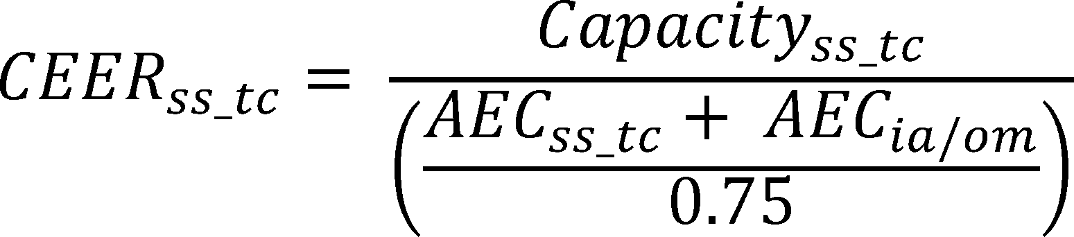
Where:
CEERss__tc = theoretical comparable single-speed room air conditioner combined energy efficiency ratio, in Btu/Wh, for each test condition in Table 1 of this appendix.
Capacityss__tc = theoretical comparable single-speed room air conditioner cooling capacity, in Btu/h, for each test condition in Table 1 of this appendix, determined in section 5.3.2 of this appendix.
AECss__tc = theoretical comparable single-speed room air conditioner annual energy consumption, in kWh/year, in cooling mode for each test condition in Table 1 of this appendix, determined in section 5.3.5 of this appendix.
AECia/om = annual energy consumption in inactive mode or off mode, in kWh/year, determined in section 5.1 of this appendix.
0.75 as defined in section 5.2.1 of this appendix.
tc as explained in section 5.3.1 of this appendix.
5.3.8 Theoretical comparable single-speed room air conditioner adjusted combined energy efficiency ratio. Calculate the adjusted combined energy efficiency ratio, for a theoretical comparable single-speed room air conditioner, CEERss__tc__adj, with cycling losses considered, for each test condition, expressed in Btu/Wh.
CEERss__tc__adj = CEERss__tc × CLFtc
Where:
CEERss__tc__adj = theoretical comparable single-speed room air conditioner adjusted combined energy efficiency ratio, in Btu/Wh, for each test condition in Table 1 of this appendix.
CEERss__tc = theoretical comparable single-speed room air conditioner combined energy efficiency ratio, in Btu/Wh, for each test condition in Table 1 of this appendix, determined in section 5.3.7 of this appendix.
CLFtc = cycling loss factor for each test condition; 1 for test condition 1, 0.956 for test condition 2, 0.883 for test condition 3, and 0.810 for test condition 4.
tc as explained in section 5.3.1 of this appendix.
5.3.9 Weighted combined energy efficiency ratio. Calculate the weighted combined energy efficiency ratio for the variable-speed room air conditioner unit, CEERwt, and theoretical comparable single-speed room air conditioner, CEERss__wt, expressed in Btu/Wh.
CEERwt = Σtc CEERtc × Wtc
CEERss__wt = Σtc CEERss__tc__adj × Wtc
Where:
CEERwt = variable-speed room air conditioner unit's weighted combined energy efficiency ratio, in Btu/Wh.
CEERss__wt = theoretical comparable single-speed room air conditioner weighted combined energy efficiency ratio, in Btu/Wh.
CEERtc = variable-speed room air conditioner unit's combined energy efficiency ratio, in Btu/Wh, at each test condition in Table 1 of this appendix, determined in section 5.3.6 of this appendix.
CEERss__tc__adj = theoretical comparable single-speed room air conditioner adjusted combined energy efficiency ratio, in Btu/Wh, at each test condition in Table 1 of this appendix, determined in section 5.3.8 of this appendix.
Wtc as defined in section 5.3.4 of this appendix.
tc as explained in section 5.3.1 of this appendix.
5.3.10 Variable-speed room air conditioner performance adjustment factor. Calculate the variable-speed room air conditioner unit's performance adjustment factor, Fp.
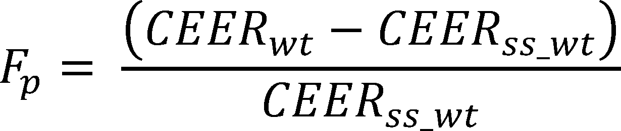
Where:
Fp = variable-speed room air conditioner unit's performance adjustment factor.
CEERwt = variable-speed room air conditioner unit's weighted combined energy efficiency ratio, in Btu/Wh, determined in section 5.3.9 of this appendix.
CEERss__wt = theoretical comparable single-speed room air conditioner weighted combined energy efficiency ratio, in Btu/Wh, determined in section 5.3.9 of this appendix.
5.3.11 Variable-speed room air conditioner combined energy efficiency ratio. Calculate the combined energy efficiency ratio, CEER, expressed in Btu/Wh, for variable-speed air conditioners.
CEER = CEER1 × (1 + Fp)
Where:
CEER = combined energy efficiency ratio, in Btu/Wh.
CEER1 = variable-speed room air conditioner combined energy efficiency ratio for test condition 1 in Table 1 of this appendix, in Btu/Wh, determined in section 5.3.6 of this appendix.
Fp = variable-speed room air conditioner performance adjustment factor, determined in section 5.3.10 of this appendix.
[86 FR 16476, Mar. 29, 2021, as amended at 86 FR 24484, May 7, 2021]
Appendix G to Subpart B of Part 430—Uniform Test Method for Measuring the Energy Consumption of Unvented Home Heating Equipment
1. Testing conditions.
1.1 Installation.
1.1.1 Electric heater. Install heater according to manufacturer's instructions. Heaters shall be connected to an electrical supply circuit of nameplate voltage with a wattmeter installed in the circuit. The wattmeter shall have a maximum error not greater than one percent.
1.1.2 Unvented gas heater. Install heater according to manufacturer's instructions. Heaters shall be connected to a gas supply line with a gas displacement meter installed between the supply line and the heater according to manufacturer's specifications. The gas displacement meter shall have a maximum error not greater than one percent. Gas heaters with electrical auxiliaries shall be connected to an electrical supply circuit of nameplate voltage with a wattmeter installed in the circuit. The wattmeter shall have a maximum error not greater than one percent.
1.1.3 Unvented oil heater. Install heater according to manufacturer's instructions. Oil heaters with electric auxiliaries shall be connected to an electrical supply circuit of nameplate voltage with a wattmeter installed in the circuit. The wattmeter shall have a maximum error not greater than one percent.
1.2 Temperature regulating controls. All temperature regulating controls shall be shorted out of the circuit or adjusted so that they will not operate during the test period.
1.3 Fan controls. All fan controls shall be set at the highest fan speed setting.
1.4 Energy supply.
1.4.1 Electrical supply. Supply power to the heater within one percent of the nameplate voltage.
1.4.2 Natural gas supply. For an unvented gas heater utilizing natural gas, maintain the gas supply to the heater with a normal inlet test pressure immediately ahead of all controls at 7 to 10 inches of water column. The regulator outlet pressure at normal supply test pressure shall be approximately that recommended by the manufacturer. The natural gas supplied should have a higher heating value within ±5 percent of 1,025 Btu's per standard cubic foot. Determine the higher heating value, in Btu's per standard cubic foot, for the natural gas to be used in the test, with an error no greater than one percent. Alternatively, the test can be conducted using “bottled” natural gas of a higher heating value within ±5 percent of 1,025 Btu's per standard cubic foot as long as the actual higher heating value of the bottled natural gas has been determined with an error no greater than one percent as certified by the supplier.
1.4.3 Propane gas supply. For an unvented gas heater utilizing propane, maintain the gas supply to the heater with a normal inlet test pressure immediately ahead of all controls at 11 to 13 inches of water column. The regulator outlet pressure at normal supply test pressure shall be that recommended by the manufacturer. The propane supplied should have a higher heating value of within±5 percent of 2,500 Btu's per standard cubic foot. Determine the higher heating value in Btu's per standard foot, for the propane to be used in the test, with an error no greater than one percent. Alternatively, the test can be conducted using “bottled” propane of a higher heating value within ±5 percent of 2,500 Btu's per standard cubic foot as long as the actual higher heating value of the bottled propane has been determined with an error no greater than one percent as certified by the supplier.
1.4.4 Oil supply. For an unvented oil heater utilizing kerosene, determine the higher heating value in Btu's per gallon with an error no greater than one percent. Alternatively, the test can be conducted using a tested fuel of a higher heating value within ±5 percent of 137,400 Btu's per gallon as long as the actual higher heating value of the tested fuel has been determined with an error no greater than one percent as certified by the supplier.
1.5 Energy flow instrumentation. Install one or more energy flow instruments which measure, as appropriate and with an error no greater than one percent, the quantity of electrical energy, natural gas, propane gas, or oil supplied to the heater.
2. Testing and measurements.
2.1 Electric power measurement. Establish the test conditions set forth in section 1 of this appendix. Allow an electric heater to warm up for at least five minutes before recording the maximum electric power measurement from the wattmeter. Record the maximum electric power (PE) expressed in kilowatts.
Allow the auxiliary electrical system of a forced air unvented gas, propane, or oil heater to operate for at least five minutes before recording the maximum auxiliary electric power measurement from the wattmeter. Record the maximum auxiliary electric power (PA) expressed in kilowatts.
2.2 Natural gas, propane, and oil measurement. Establish the test conditions as set forth in section 1 of this appendix. A natural gas, propane, or oil heater shall be operated for one hour. Using either the nameplate rating or the energy flow instrumentation set forth in section 1.5 of this appendix and the fuel supply rating set forth in sections 1.4.2, 1.4.3, or 1.4.4 of this appendix, as appropriate, determine the maximum fuel input (PF) of the heater under test in Btu's per hour. The energy flow instrumentation shall measure the maximum fuel input with an error no greater than one percent.
2.3 Pilot light measurement. Except as provided in section 2.3.1 of this appendix, measure the energy input rate to the pilot light (Qp), with an error no greater than 3 percent, for unvented heaters so equipped.
2.3.1 The measurement of Qp is not required for unvented heaters where the pilot light is designed to be turned off by the user when the heater is not in use (i.e., for units where turning the control to the OFF position will shut off the gas supply to the burner(s) and the pilot light). This provision applies only if an instruction to turn off the unit is provided on the heater near the gas control value (e.g., by label) by the manufacturer.
2.4 Electrical standby mode power measurement. Except as provided in section 2.4.1 of this appendix, for all electric heaters and unvented heaters with electrical auxiliaries, measure the standby power (PW,SB) in accordance with the procedures in IEC 62301 Second Edition (incorporated by reference; see § 430.3), with all electrical auxiliaries not activated. Voltage shall be as specified in section 1.4.1 Electrical supply of this appendix. The recorded standby power (PW,SB) shall be rounded to the second decimal place, and for loads greater than or equal to 10W, at least three significant figures shall be reported.
2.4.1 The measurement of PW,SB is not required for heaters designed to be turned off by the user when the heater is not in use (i.e., for units where turning the control to the OFF position will shut off the electrical supply to the heater). This provision applies only if an instruction to turn off the unit is provided on the heater (e.g., by label) by the manufacturer.
3. Calculations.
3.1 Annual energy consumption for primary electric heaters. For primary electric heaters, calculate the annual energy consumption (EE) expressed in kilowatt-hours per year and defined as:
EE = 2080(0.77)DHR
where:
2080 = national average annual heating load hours
0.77 = adjustment factor
DHR = design heating requirement and is equal to PE /1.2 in kilowatts.
PE = as defined in 2.1 of this appendix
1.2 = typical oversizing factor for primary electric heaters
3.2 Annual energy consumption for primary electric heaters by geographic region of the United States. For primary electric heaters, calculate the annual energy consumption by geographic region of the United States (ER) expressed in kilowatt-hours per year and defined as:
ER = HLH(0.77) (DHR)
where:
HLH = heating load hours for a specific region determined from Figure 1 of this appendix in hours
0.77 = as defined in 3.1 of this appendix
DHR = as defined in 3.1 of this appendix
3.3 Rated output for electric heaters. Calculate the rated output (Qout) for electric heaters, expressed in Btu's per hour, and defined as:
Qout = PE (3,412 Btu/kWh)
where:
PE = as defined in 2.1 of this appendix
3.4 Rated output for unvented heaters using either natural gas, propane, or oil. For unvented heaters using either natural gas, propane, or oil equipped without auxiliary electrical systems, the rated output (Qout), expressed in Btu's per hour, is equal to PF, as determined in section 2.2 of this appendix.
For unvented heaters using either natural gas, propane, or oil equipped with auxiliary electrical systems, calculate the rated output (Qout), expressed in Btu's per hour, and defined as:
Qout = PF + PA (3,412 Btu/kWh)
where:
PF = as defined in 2.2 of this appendix in Btu/hr
PA = as defined in 2.1 of this appendix in Btu/hr
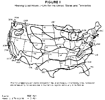
[43 FR 20132, May 10, 1978. Redesignated and amended at 44 FR 37938, June 29, 1979; 49 FR 12157, Mar. 28, 1984; 77 FR 74571, Dec. 17, 2012]
Appendix H to Subpart B of Part 430 - Uniform Test Method for Measuring the Power Consumption of Television Sets
After April 23, 2014, any representations made with respect to the energy use or efficiency of televisions must be made in accordance with the results of testing pursuant to this appendix. Given that after April 23, 2014 representations with respect to the energy use or efficiency of televisions must be made in accordance with tests conducted pursuant to this appendix, manufacturers may wish to begin using this test procedure as soon as possible.
1. Scope
This appendix covers the test requirements used to measure the energy and power consumption of television sets that:
(i) Have a diagonal screen size of at least fifteen inches; and
(ii) Are powered by mains power (including TVs with auxiliary batteries but not TVs with main batteries).
2. Definitions and Symbols
2.1. Additional functions shall be defined using the additional functions definition in section 3.1.1 of IEC 62087 Ed. 3.0 (incorporated by reference, see § 430.3).
2.2. Auxiliary Battery means a battery capable of powering a clock or retaining TV settings but is incapable of powering the TV to produce dynamic video.
2.3. Brightest selectable preset picture setting means the preset picture setting in which the television produces the highest screen luminance within either the home or retail configuration.
2.4. Default picture setting means the preset picture setting that the TV enters into immediately after making a selection from the forced menu. If the TV does not have a forced menu, this is the as-shipped preset picture setting.
2.5. Forced menu means a series of menus which require the selection of initial settings before allowing the user to utilize primary functions. Within these menus contains an option to choose the viewing environment between retail and home configurations.
2.6. Home configuration means the TV configuration selected from the forced menu which is designed for typical consumer viewing and is recommended by the manufacturer for home environments.
2.7. IEC 62087 Ed. 3.0 means the test standard published by the International Electrotechnical Commission, entitled “Methods of measurement of the power consumption of audio, video, and related equipment,” IEC 62087 Ed. 3.0 (incorporated by reference, see § 430.3).
2.8. IEC 62087 Ed. 3.0 Blu-ray DiscTM Dynamic Broadcast-Content Video Signal means the test video content published by the International Electrotechnical Commission, entitled “IEC 62087 Ed. 3.0, video content__BD, video content for IEC 62087 Ed. 3.0 on Blu-rayTM Disc,” IEC 62087 Ed. 3.0 (incorporated by reference, see § 430.3).
2.9. IEC 62301 Ed. 2.0 means the test standard published by the International Electrotechnical Commission, entitled “Household electrical appliances - Measurement of standby power,” IEC 62301 Ed. 2.0 (incorporated by reference, see § 430.3).
2.10. Illuminance means the luminous flux per unit area of light illuminating a given surface, expressed in units of lux (lx).
2.11. Luminance means the photometric measure of the luminous intensity per unit area of light traveling in a given direction, expressed in units of candelas per square meter (cd/m2).
2.12. Main battery means a battery capable of powering the TV to produce dynamic video without the support of mains power.
2.13. Off mode means the mode of operation in which the TV is connected to mains power, produces neither sound nor picture, and cannot be switched into any other mode of operation with the remote control unit, an internal signal, or external signal.
2.14. On mode means the mode of operation in which the TV is connected to mains power, and is capable of producing dynamic video.
2.15. Preset picture setting means a preprogrammed factory setting obtained from the TV menu with pre-determined picture parameters such as brightness, contrast, color, sharpness, etc. Preset picture settings can be selected within the home or retail mode.
2.16. Retail configuration means the TV configuration selected from the forced menu which is designed to highlight the TV's features in a retail environment. This configuration may display demos, disable configurable settings, or increase screen brightness in a manner which is not desirable for typical consumer viewing.
2.17. Special functions shall be defined using the definition in section 3.1.18 of IEC 62087 Ed. 3.0 (incorporated by reference, see § 430.3).
2.18. Standby-passive mode means the mode of operation in which the TV is connected to mains power, produces neither sound nor picture, and can be switched into another mode with only the remote control unit or an internal signal.
2.19. Standby-active, high mode means the mode of operation in which the TV is connected to mains power, produces neither sound nor picture, is exchanging/receiving data with/from an external source, and can be switched into another mode of operation with the remote control unit, an internal signal, or an external signal.
2.20. Standby-active, low mode means the mode of operation in which the TV is connected to mains power, produces neither sound nor picture, can be switched into another mode with the remote control unit or an internal signal, and can additionally be switched into another mode with an external signal.
2.21. Symbol usage. The following identity relationships are provided to help clarify the symbols used throughout this test procedure.
ABC - Automatic Brightness Control
AEC - Annual Energy Consumption
BD - Blu-ray DiscTM
DVD - Digital Versatile DiscTM
DVI - Digital Visual Interface
HDMI® - High Definition Multimedia Interface
Lbrightest - Screen luminance in brightest selectable preset picture setting within the home configuration
Ldefault - Screen luminance in default picture setting within the home configuration
Ldefault__retail - Screen luminance in default picture setting within the retail configuration
LAN - Local Area Network
Pon - Power consumed in on mode
P3 - Average power consumed in on mode, ABC enabled, 3 lx
P12 - Average power consumed in on mode, ABC enabled, 12 lx
P35 - Average power consumed in on mode, ABC enabled, 35 lx
P100 - Average power consumed in on mode, ABC enabled, 100 lx
Pstandby-passive - Power consumption in standby-passive mode
Pstandby-active, low - Power consumption in standby-active, low mode
Poff - Power consumption in off mode
STB - Set-top Box
THD - Total Harmonic Distortion
TV - Television Set
USB - Universal Serial Bus
W3 - Percent weighting for on mode, ABC enabled, 3 lx
W12 - Percent weighting for on mode, ABC enabled, 12 lx
W35 - Percent weighting for on mode, ABC enabled, 35 lx
W100 - Percent weighting for on mode, ABC enabled, 100 lx
WAN - Wide Area Network
3. Accuracy and Precision of Measurement Equipment
3.1. Voltage and Frequency. Set the test voltage and frequency to the rated electrical supply values of the region in accordance with Table 1 in section 4.3.1 of IEC 62301 Ed. 2.0
3.2. Power Supply Requirements. The TV power use shall be measured using a power supply that meets the specifications found in section 4.3.1 of IEC 62301 Ed. 2.0 (incorporated by reference, see § 430.3). The THD of the supply voltage shall not exceed 5%, inclusive to the 13th order harmonic, when the unit is under test.
3.3. Power Meter Requirements. The power measurement shall be carried out directly by means of a wattmeter, a wattmeter with averaging function, or a watt-hour meter by dividing the reading by the measuring time. For TVs where the input video signal varies over time, use a wattmeter with an averaging function to carry out the measurement.
3.3.1. The sampling rate of the watt-hour meter or wattmeter with averaging function shall be one measurement per second or more frequent.
3.3.2. The power measurement instrument shall measure and record the power factor and the real power consumed during all on mode tests at the same sampling rate.
3.3.3. Power measurements of 0.5 W or greater shall be made with an uncertainty of less than or equal to 2 percent (at the 95 percent confidence level). Measurements of power of less than 0.5 W shall be made with an uncertainty of less than or equal to 0.01 W (at the 95 percent confidence level). The power measurement instrument shall have a resolution of:
0.01 W or better for power measurements of 10 W or less;
0.1 W or better for power measurements of greater than 10 W up to 100 W;
1 W or better for power measurements of greater than 100 W.
3.4. Luminance Meter Requirements. Contact or non-contact luminance meters shall have an accuracy of ±2 percent ±2 digits of the digitally displayed value. Non-contact meters are also required to have an acceptance angle of 3 degrees or less.
3.5. Illuminance Meter Requirements. All illuminance meters shall have an accuracy of ±2 percent ±2 digits of the digitally displayed value.
3.6. Video Input Device. The video input device (i.e. BD player) shall be capable of decoding a BD signal. The video input device manufacturer shall be different from the manufacturer of the TV under test to prevent device interaction.
4. Test Room Set-Up
4.1. Ambient Temperature Conditions. For all testing, maintain ambient temperature conditions in accordance with in section 11.4.1 of IEC 62087 Ed. 3.0 (incorporated by reference, see § 430.3).
4.2. Ambient Relative Humidity Conditions. For all testing, maintain the ambient relative humidity between 10 and 80 percent.
4.3. Room Illuminance Level. All luminance testing (with a non-contact meter) and on mode testing (with ABC enabled by default) shall be performed in a room which measures less than or equal to 1.0 lx measured at the ABC sensor while the TV is in off or a standby mode. If the TV does not have an ABC sensor, measure at the bottom center of the TV bezel.
4.4. Installation. Install the TV in accordance with manufacturer's instructions.
4.5. TV Placement. TVs which have an ABC sensor enabled by default shall be placed at least 0.5 meters away from any wall surface (i.e. wall, ceiling, and floor). This does not include the furnishings which the TV may be placed on or the wall which the back of the TV faces. All four corners of the face of the TV shall be placed equidistant from a vertical reference plane (e.g. wall).
5. TV and Video Signal Configuration
5.1. Additional Functions. The TV shall be set up according to the requirements in section 11.4.5 of IEC 62087 Ed. 3.0 (incorporated by reference, see § 430.3).
5.2. Video Connection Priority. The TV and the video input device shall be connected using an HDMI input cable. If the TV does not have an HDMI input terminal, the specified input terminals shall be used in the following order: Component video, S-video, and Composite video.
5.3. Input Terminal. If the TV has multiple input terminals of the same type (i.e. HDMI 1, HDMI 2), testing shall only be performed using any input terminal designed for viewing live TV or dynamic content from a BD player or STB, not from an input designed for an alternative purpose. Examples 1 and 2 provide visual explanations of this requirement.

5.4. Special Functions. The TV shall be set up according to the requirements in section 11.4.6 of IEC 62087 Ed. 3.0 (incorporated by reference, see § 430.3).
5.5. Special Function Configuration. If at any time during on mode operation a message prompt is displayed requesting the configuration of special functions, the most power consumptive configuration shall be selected. If it is unknown which configuration yields the most power consumptive state, verify the selection by measuring the power consumption of each possible configuration.
The selection of the home or retail configuration within the forced menu is not considered the configuration of a special function, and is therefore exempt from this requirement.
5.6. On Mode Picture Setting. Ensure that the TV is in the default picture setting within the home configuration for all on mode tests. This picture setting shall only be changed as instructed by the luminance test.
5.7. Video Aspect Ratio. The input video signal shall be configured in accordance with section 11.4.9 of IEC 62087 Ed. 3.0 (incorporated by reference; see § 430.3)
5.8. Frame Rate. The video frame rate shall be selected in accordance with section 11.4.10 of IEC 62087 Ed. 3.0 (incorporated by reference; see § 430.3)
5.9. Sound level. The TV sound level shall be configured in accordance with section 11.4.11 of IEC 62087 Ed. 3.0 (incorporated by reference; see § 430.3)
5.10. Network Connection Configuration.
5.10.1. Network Connections and Capabilities. Network connections should be listed in the user manual. If no connections are specified in the user manual, verify that the TV does not have network capabilities by checking for the absence of physical connections and the absence of network settings in the menu. If the TV has the capability to be connected to a network but was not shipped with a required piece of hardware (e.g. wireless adapter), that connection type shall not be tested.
5.10.2. Network Configuration. If the TV is network enabled, connect it to a LAN in on mode and prior to being placed into standby mode. The LAN shall allow devices to ping other devices on the network but will not allow access to a WAN. If the TV has multiple network connections (e.g., Wi-Fi and Ethernet), the TV shall be configured and connected to a single network source in accordance with the hierarchy of connections listed in Table 1 of this section.
Table 1 - Network Connection Hierarchy
| Priority | Network connection type |
|---|---|
| 1 | Wi-Fi (Institution of Electrical and Electronics Engineers - IEEE 802.11-20072) |
| 2 | Ethernet (IEEE 802.3). If the TV supports Energy Efficient Ethernet (IEEE 802.3az-20103), then it shall be connected to a device that also supports IEEE 802.3az. |
6. Calculation of Average Power Consumption
6.1. Average Power Calculation. For all tests in the on, standby-active, low, and standby-passive modes, the average power shall be calculated using one of the following two methods:
6.1.1. Record the accumulated energy (Ei) in kilo-watt hours (kWh) consumed over the time period specified for each test (Ti). The average power consumption is calculated as Pi = Ei/Ti.
6.1.2. Record the average power consumption (Pi) by sampling the power at a rate of at least 1 sample per second and computing the arithmetic mean of all samples over the time period specified for each test (Ti).
The resulting average power consumption value for each mode of operation shall be rounded according to the accurary requirements specified in section 3.3.3 of this section.
7. Test Measurements.
7.1. On Mode Test.
7.1.1. On Mode Stabilization. If the TV has an ABC sensor enabled by default, direct at least 300 lx into the ABC sensor. The TV shall be stabilized prior to testing on mode using the IEC 62087 Ed. 3.0 Blu-ray DiscTM dynamic broadcast-content video signal in accordance with section 11.4.2 of IEC 62087 Ed. 3.0 (incorporated by reference, see § 430.3).
7.1.2. On Mode Test for TVs without ABC Enabled by Default. The following test shall be performed if the TV is shipped with ABC disabled by default or the ABC function is unavailable. Display the IEC 62087 Ed. 3.0 Blu-ray DiscTM dynamic broadcast-content video signal for one 10-minute period (incorporated by reference, see § 430.3). Measure and record the average power consumption value over the test duration as Pon.
7.1.3. On Mode Test for TVs with ABC Enabled by Default. The following test shall be performed if the TV is shipped with ABC enabled by default:
7.1.3.1. Illuminance Values. Display the IEC 62087 Ed. 3.0 Blu-ray DiscTM dynamic broadcast-content video signal for one 10-minute period (incorporated by reference, see § 430.3) with 100 lx (±5 lx) entering the ABC sensor. Measure and record the average power consumption value over the test duration as P100. Repeat the measurements with 35 lx (±2 lx), 12 lx (±1 lx), and 3 lux (±1 lx) entering the ABC sensor and record the values as P35, P12, and P3 respectively. Testing shall be performed from the brightest to dimmest illuminance value and the values shall be changed by varying the input voltage to the light source.
The 3 lx illuminance value shall be simulated using a 67 mm 2 F-stop neutral density filter. 12 lx is measured at the ABC sensor prior to the application of the neutral density filter.
7.1.3.2. On Mode Power Calculation. All illuminance values shall be weighted equally when calculating the on mode power for a TV with ABC enabled by default and shall be determined by the following equation:
Pon = P100 * W100 + P35 * W35 + P12 * W12 + P3 * W3
Where:
W100 = W35 = W12 = W3 = 0.25
7.1.3.3. Lamp Requirements. A standard spectrum, halogen incandescent aluminized reflector lamp with a lamp diameter of 95 mm (±10 mm), a beam angle of 30 degrees (±10 degrees), and a center beam candlepower of 1500 cd (±500 cd) shall be positioned in front of the ABC sensor so that the light is directed into the sensor.
Lamps with spectrum modifying qualities, such as an IR coating, are not considered to meet a standard spectrum.
7.1.3.4. Light Source Set-up. The center of the lamp shall measure 1.5 m (±0.1 m) from the center of the ABC sensor. The light source shall be aligned ensuring that the center focal point of the lamp is perpendicular to the center of the ABC sensor.
7.1.3.5. Illuminance Measurement. The room illuminance shall be measured at the sensor in the direction of the light source while the TV is on and displaying the first menu from the IEC 62087 Ed. 3.0 Blu-ray DiscTM dynamic broadcast-content video signal.
7.2. Luminance Test.
7.2.1. Luminance Test Set-up.
7.2.1.1. Picture Setting Set-up. When transitioning from the on mode power consumption test to the luminance test, the TV shall remain in the default picture setting within the home configuration for the first luminance measurement.
7.2.1.2. ABC Configuration. The ABC sensor shall be disabled at all times during the luminance test. If the ABC sensor is incapable of being disabled through the TV settings menu, direct at least 300 lx of light into the ABC sensor.
7.2.1.3. Stabilization. Prior to the first luminance measurement, the TV must undergo a 10-minute re-stabilization period using the IEC 62087 Ed. 3.0 Blu-ray DiscTM dynamic broadcast-content video signal.
7.2.2. Luminance Meter Set-up. Align the luminance meter perpendicular to the center of the TV screen. If a non-contact luminance meter is used to measure the screen luminance, the luminance measurement shall be taken at a distance capable of meeting the meter specifications outlined in section 3.1.3, and in accordance with the meter's user manual.
7.2.3. Three Vertical Bar Signal Measurement. The IEC 62087 Ed. 3.0 three vertical bar signal found in section 11.5.5 of IEC 62087 Ed. 3.0 (incorporated by reference, see § 430.3) shall be displayed for no more than 5 seconds when each luminance measurement is taken. The luminance measurement taken in the default picture setting within the home configuration shall be recorded as LDefault__Home.
7.2.4. Luminance in the Brightest Selectable Preset Picture Setting. Using the IEC 62087 Ed. 3.0 three vertical bar signal, determine the brightest selectable preset picture setting within the home configuration. Measure and record the screen luminance in the brightest selectable preset picture setting as LBrightest__Home.
7.2.5. Retail Configuration Luminance Measurement. If the TV has a retail configuration and the retail configuration is acceptable for making a luminance measurement, measure and record the screen luminance in the default picture setting within the retail configuration as LDefault__Retail. A retail configuration is considered acceptable for a luminance measurement if the TV does not display a demo or ticker which alters the screen content, or if such features are present, they must be capable of being disabled for the entire re-stabilization period and measurement.
7.3. Standby Mode Test.
7.3.1. Video Input Device. The video input device shall be disconnected from the TV for all testing in standby mode.
7.3.2. Standby-Passive Mode. The standby-passive mode test shall be performed according to section 5.3.1 of IEC 62301 Ed. 2.0 (incorporated by reference, see § 430.3). Measure and record the average power consumption value over the test duration as Pstandby-passive.
7.3.3. Standby-Active, Low Mode. The standby-active, low mode shall only be tested if the TV is capable of connecting to a network and is capable of entering this mode of operation. The standby-active, low mode test shall be performed according to section 5.3.1 of IEC 62301 Ed. 2.0 (incorporated by reference, see § 430.3). Measure and record the average power consumption value over the test duration as Pstandby-active,low.
7.4. Off Mode Test.
7.4.1. The off mode test shall be performed according to section 5.3.1 of IEC 62301 Ed. 2.0 (incorporated by reference, see § 430.3). Measure and record the average power consumption value over the test duration as Poff.
8. Annual Energy Consumption
8.1. Input Value. The annual energy consumption (AEC) of the TV shall be calculated using on mode, standby mode, and off mode power consumption values as measured pursuant to section 7.1, 7.3, and 7.4 respectively.
8.2. Rounding. Calculate the AEC of the TV using the equation below. The calculated AEC value shall be rounded as follows:
If the calculated AEC value is 100 kWh or less, the rated value shall be rounded to the nearest tenth of a kWh;
If the calculated AEC value is greater than 100 kWh, the rated value shall be rounded to the nearest kWh.
8.3. Calculations. Express the AEC in kWh per year, according to the following:
AEC = 365 * (Pon * Hon + Pstandby-active, low * Hstandby-active, low + Pstandby-passive * Hstandby-passive + Poff * Hoff)/1000
Where:
Pm = power measured in a given mode m (in Watts)
Hm = hours per day spent in mode m
365 = conversion factor from daily to yearly
1000 = conversion factor from watts to kilowatts
Values for Hm (in hours/day) are specified in Table 2 of this section:
Table 2 - Hourly Weightings
| Standby-active, low mode | Hon | Hstandby-active, low | Hstandby-passive | Hoff |
|---|---|---|---|---|
| Yes | 5 | 19 | 0 | 0 |
| No | 5 | 0 | 19 | 0 |
[78 FR 63841, Oct. 25, 2013]
Appendix I to Subpart B of Part 430 - Uniform Test Method for Measuring the Energy Consumption of Cooking Products
1. Definitions
The following definitions apply to the test procedures in this appendix, including the test procedures incorporated by reference:
1.1 Active mode means a mode in which the product is connected to a mains power source, has been activated, and is performing the main function of producing heat by means of a gas flame, electric resistance heating, electric inductive heating, or microwave energy.
1.2 Built-in means the product is enclosed in surrounding cabinetry, walls, or other similar structures on at least three sides, and can be supported by surrounding cabinetry or the floor.
1.3 Combined cooking product means a household cooking appliance that combines a cooking product with other appliance functionality, which may or may not include another cooking product. Combined cooking products include the following products: Conventional range, microwave/conventional cooking top, microwave/conventional oven, and microwave/conventional range.
1.4 Drop-in means the product is supported by horizontal surface cabinetry.
1.5 IEC 62301 (First Edition) means the test standard published by the International Electrotechnical Commission, titled “Household electrical appliances - Measurement of standby power,” Publication 62301 (First Edition 2005-06) (incorporated by reference; see § 430.3).
1.6 IEC 62301 (Second Edition) means the test standard published by the International Electrotechnical Commission, titled “Household electrical appliances - Measurement of standby power,” Publication 62301 (Edition 2.0 2011-01) (incorporated by reference; see § 430.3).
1.7 Normal non-operating temperature means a temperature of all areas of an appliance to be tested that is within 5 °F (2.8 °C) of the temperature that the identical areas of the same basic model of the appliance would attain if it remained in the test room for 24 hours while not operating with all oven doors closed.
1.8 Off mode means any mode in which a cooking product is connected to a mains power source and is not providing any active mode or standby function, and where the mode may persist for an indefinite time. An indicator that only shows the user that the product is in the off position is included within the classification of an off mode.
1.9 Standby mode means any mode in which a cooking product is connected to a mains power source and offers one or more of the following user-oriented or protective functions which may persist for an indefinite time:
(1) Facilitation of the activation of other modes (including activation or deactivation of active mode) by remote switch (including remote control), internal sensor, or timer;
(2) Provision of continuous functions, including information or status displays (including clocks) or sensor-based functions. A timer is a continuous clock function (which may or may not be associated with a display) that allows for regularly scheduled tasks and that operates on a continuous basis.
2. Test Conditions
2.1 Installation. Install a drop-in or built-in cooking product in a test enclosure in accordance with manufacturer's instructions. If the manufacturer's instructions specify that the cooking product may be used in multiple installation conditions, install the appliance according to the built-in configuration. Completely assemble the product with all handles, knobs, guards, and similar components mounted in place. Position any electric resistance heaters and baffles in accordance with the manufacturer's instructions.
2.1.1 Microwave ovens, excluding any microwave oven component of a combined cooking product. Install the microwave oven in accordance with the manufacturer's instructions and connect to an electrical supply circuit with voltage as specified in section 2.2.1 of this appendix. Install the microwave oven also in accordance with Section 5, Paragraph 5.2 of IEC 62301 (Second Edition) (incorporated by reference; see § 430.3), disregarding the provisions regarding batteries and the determination, classification, and testing of relevant modes. A watt meter shall be installed in the circuit and shall be as described in section 2.6.1.1 of this appendix.
2.2 Energy supply.
2.2.1 Electrical supply.
2.2.1.1 Voltage. For microwave oven testing, maintain the electrical supply to the unit at 240/120 volts ±1 percent. Maintain the electrical supply frequency for all products at 60 hertz ±1 percent.
2.3 Air circulation. Maintain air circulation in the room sufficient to secure a reasonably uniform temperature distribution, but do not cause a direct draft on the unit under test.
2.4 Ambient room test conditions.
2.4.1 Standby mode and off mode ambient temperature. For standby mode and off mode testing, maintain room ambient air temperature conditions as specified in Section 4, Paragraph 4.2 of IEC 62301 (Second Edition) (incorporated by reference; see § 430.3).
2.5 Normal non-operating temperature. All areas of the appliance to be tested must attain the normal non-operating temperature, as defined in section 1.7 of this appendix, before any testing begins. Measure the applicable normal non-operating temperature using the equipment specified in sections 2.6.2.1 of this appendix.
2.6 Instrumentation. Perform all test measurements using the following instruments, as appropriate:
2.6.1 Electrical Measurements.
2.6.1.1 Standby mode and off mode watt meter. The watt meter used to measure standby mode and off mode power must meet the requirements specified in Section 4, Paragraph 4.4 of IEC 62301 (Second Edition) (incorporated by reference; see § 430.3). For microwave oven standby mode and off mode testing, if the power measuring instrument used for testing is unable to measure and record the crest factor, power factor, or maximum current ratio during the test measurement period, measure the crest factor, power factor, and maximum current ratio immediately before and after the test measurement period to determine whether these characteristics meet the requirements specified in Section 4, Paragraph 4.4 of IEC 62301 (Second Edition).
2.6.2 Temperature measurement equipment.
2.6.2.1 Room temperature indicating system. For the test of microwave ovens, the room temperature indicating system must have an error no greater than ±1 °F (±0.6 °C) over the range 65° to 90 °F (18 °C to 32 °C).
3. Test Methods and Measurements
3.1. Test methods.
3.1.1 Microwave oven.
3.1.1.1 Microwave oven test standby mode and off mode power except for any microwave oven component of a combined cooking product. Establish the testing conditions set forth in section 2, Test Conditions, of this appendix. For microwave ovens that drop from a higher power state to a lower power state as discussed in Section 5, Paragraph 5.1, Note 1 of IEC 62301 (Second Edition) (incorporated by reference; see § 430.3), allow sufficient time for the microwave oven to reach the lower power state before proceeding with the test measurement. Follow the test procedure as specified in Section 5, Paragraph 5.3.2 of IEC 62301 (Second Edition). For units in which power varies as a function of displayed time in standby mode, set the clock time to 3:23 and use the average power approach described in Section 5, Paragraph 5.3.2(a) of IEC 62301 (First Edition), but with a single test period of 10 minutes +0/−2 sec after an additional stabilization period until the clock time reaches 3:33. If a microwave oven is capable of operation in either standby mode or off mode, as defined in sections 1.9 and 1.8 of this appendix, respectively, or both, test the microwave oven in each mode in which it can operate.
3.2 Test measurements.
3.2.1 Microwave oven standby mode and off mode power except for any microwave oven component of a combined cooking product. Make measurements as specified in Section 5, Paragraph 5.3 of IEC 62301 (Second Edition) (incorporated by reference; see § 430.3). If the microwave oven is capable of operating in standby mode, as defined in section 1.9 of this appendix, measure the average standby mode power of the microwave oven, PSB, in watts as specified in section 3.1.1.1 of this appendix. If the microwave oven is capable of operating in off mode, as defined in section 1.8 of this appendix, measure the average off mode power of the microwave oven, POM, as specified in section 3.1.1.1.
3.3 Recorded values.
3.3.1 For microwave ovens except for any microwave oven component of a combined cooking product, record the average standby mode power, PSB, for the microwave oven standby mode, as determined in section 3.2.1 of this appendix for a microwave oven capable of operating in standby mode. Record the average off mode power, POM, for the microwave oven off mode power test, as determined in section 3.2.1 of this appendix for a microwave oven capable of operating in off mode.
[85 FR 50766, Aug. 18, 2020]
Appendix J1 to Subpart B of Part 430 - Uniform Test Method for Measuring the Energy Consumption of Automatic and Semi-Automatic Clothes Washers
Any representation related to the energy or water consumption of a residential clothes washer must be based upon results generated using Appendix J2.
Before January 1, 2018, any representation related to the energy or water consumption of commercial clothes washers must be based on results generated using Appendix J1. Specifically, before February 1, 2016, representations must be based upon results generated either under this appendix or under Appendix J1 as it appeared in the 10 CFR parts 200-499 edition revised as of January 1, 2015. Any representations made on or after February 1, 2016, but before January 1, 2018, must be made based upon results generated using this appendix. Any representations made on or after January 1, 2018, must be based upon results generated using Appendix J2.
1. Definitions and Symbols
1.1 Adaptive control system means a clothes washer control system, other than an adaptive water fill control system, that is capable of automatically adjusting washer operation or washing conditions based on characteristics of the clothes load placed in the clothes container, without allowing or requiring user intervention or actions. The automatic adjustments may, for example, include automatic selection, modification, or control of any of the following: Wash water temperature, agitation or tumble cycle time, number of rinse cycles, or spin speed. The characteristics of the clothes load, which could trigger such adjustments, could, for example, consist of or be indicated by the presence of either soil, soap, suds, or any other additive laundering substitute or complementary product.
1.2 Adaptive water fill control system means a clothes washer automatic water fill control system that is capable of automatically adjusting the water fill level based on the size or weight of the clothes load placed in the clothes container.
1.3 Automatic water fill control system means a clothes washer water fill control system that does not allow or require the user to determine or select the water fill level, and includes adaptive water fill control systems and fixed water fill control systems.
1.4 Bone-dry means a condition of a load of test cloth which has been dried in a dryer at maximum temperature for a minimum of 10 minutes, removed and weighed before cool down, and then dried again for 10 minute periods until the final weight change of the load is 1 percent or less.
1.5 Clothes container means the compartment within the clothes washer that holds the clothes during the operation of the machine.
1.6 Compact means a clothes washer which has a clothes container capacity of less than 1.6 ft3 (45 L).
1.7 Deep rinse cycle means a rinse cycle in which the clothes container is filled with water to a selected level and the clothes load is rinsed by agitating it or tumbling it through the water.
1.8 Energy test cycle for a basic model includes:
(A) All wash/rinse temperature selections and water levels offered in the cycle recommended by the manufacturer for washing cotton or linen clothes, and
(B) For each other wash/rinse temperature selection or water level available on that basic model, the portion(s) of other cycle(s) with that temperature selection or water level that, when tested pursuant to these test procedures, will contribute to an accurate representation of the energy consumption of the basic model as used by end users.
If a warm rinse temperature selection is available on the clothes washer but is not available in the cycle recommended for washing cotton or linen clothes, the energy test cycle shall include the warm rinse temperature selection in the cycle most comparable to the cycle recommended for washing cotton or linen clothes.
If an extra-hot temperature selection is available only on a sanitization cycle, the sanitization cycle should be included in the energy test cycle if the cycle is recommended by the manufacturer for washing clothing. If the extra-hot temperature selection is available only on a sanitization cycle not recommended by the manufacturer for washing clothing (e.g., a cycle intended only for sanitizing the wash drum), such a cycle is not required for consideration as part of the energy test cycle.
(C) For clothes washers with electronic control systems, use the manufacturer default settings for any cycle selections, except for
(1) the temperature selection,
(2) the wash water fill levels, or
(3) if necessary, the spin speeds on wash cycles used to determine remaining moisture content. Specifically, the manufacturer default settings must be used for wash conditions such as agitation/tumble operation, soil level, spin speed on wash cycles used to determine energy and water consumption, wash times, rinse times, optional rinse settings, water heating time for water-heating clothes washers, and all other wash parameters or optional features applicable to that wash cycle. Any optional wash cycle feature or setting (other than wash/rinse temperature, water fill level selection, or spin speed on wash cycles used to determine remaining moisture content) that is activated by default on the wash cycle under test must be included for testing unless the manufacturer instructions recommend not selecting this option, or recommend selecting a different option, for washing normally soiled cotton clothing.
For clothes washers with control panels containing mechanical switches or dials, any optional settings, except for (1) the temperature selection, (2) the wash water fill levels, or (3) if necessary, the spin speeds on wash cycles used to determine remaining moisture content, must be in the position recommended by the manufacturer for washing normally soiled cotton clothing. If the manufacturer instructions do not recommend a particular switch or dial position to be used for washing normally soiled cotton clothing, the setting switch or dial must remain in its as-shipped position.
(D) The determination of the energy test cycle must take into consideration all cycle settings available to the end user, including any cycle selections or cycle modifications provided by the manufacturer via software or firmware updates to the product, for the basic model under test.
1.9 Fixed water fill control system means a clothes washer automatic water fill control system that automatically terminates the fill when the water reaches an appropriate level in the clothes container.
1.10 Load use factor means the percentage of the total number of wash loads that a user would wash a particular size (weight) load.
1.11 Manual control system means a clothes washer control system that requires that the user make the choices that determine washer operation or washing conditions, such as, for example, wash/rinse temperature selections, and wash time before starting the cycle.
1.12 Manual water fill control system means a clothes washer water fill control system that requires the user to determine or select the water fill level.
1.13 Modified energy factor means the quotient of the cubic foot (or liter) capacity of the clothes container divided by the total clothes washer energy consumption per cycle, with such energy consumption expressed as the sum of the machine electrical energy consumption, the hot water energy consumption, and the energy required for removal of the remaining moisture in the wash load.
1.14 Non-water-heating clothes washer means a clothes washer which does not have an internal water heating device to generate hot water.
1.15 Spray rinse cycle means a rinse cycle in which water is sprayed onto the clothes for a period of time without maintaining any specific water level in the clothes container.
1.16 Standard means a clothes washer which has a clothes container capacity of 1.6 ft3 (45 L) or greater.
1.17 Temperature use factor means, for a particular wash/rinse temperature setting, the percentage of the total number of wash loads that an average user would wash with that setting.
1.18 Thermostatically controlled water valves means clothes washer controls that have the ability to sense and adjust the hot and cold supply water.
1.19 Warm wash means all wash temperature selections that are below the hottest hot, less than 135 °F (57.2 °C), and above the coldest cold temperature selection.
1.20 Water factor means the quotient of the total weighted per-cycle water consumption divided by the cubic foot (or liter) capacity of the clothes washer.
1.21 Water-heating clothes washer means a clothes washer where some or all of the hot water for clothes washing is generated by a water heating device internal to the clothes washer.
1.22 Symbol usage. The following identity relationships are provided to help clarify the symbology used throughout this procedure.
E - Electrical Energy Consumption
H - Hot Water Consumption
C - Cold Water Consumption
R - Hot Water Consumed by Warm Rinse
ER - Electrical Energy Consumed by Warm Rinse
TUF - Temperature Use Factor
HE - Hot Water Energy Consumption
F - Load Usage Factor
Q - Total Water Consumption
ME - Machine Electrical Energy Consumption
RMC - Remaining Moisture Content
WI - Initial Weight of Dry Test Load
WC - Weight of Test Load After Extraction
m - Extra Hot Wash (maximum wash temp. >135 °F (57.2 °C.))
h - Hot Wash (maximum wash temp. ≤135 °F (57.2 °C.))
w - Warm Wash
c - Cold Wash (minimum wash temp.)
r - Warm Rinse (hottest rinse temp.)
x or max - Maximum Test Load
a or avg - Average Test Load
n or min - Minimum Test Load
The following examples are provided to show how the above symbols can be used to define variables:
Emx = “Electrical Energy Consumption” for an “Extra Hot Wash” and “Maximum Test Load”
Ra = “Hot Water Consumed by Warm Rinse” for the “Average Test Load”
TUFm = “Temperature Use Factor” for an “Extra Hot Wash”
HEmin = “Hot Water Energy Consumption” for the “Minimum Test Load”
1.23 Cold rinse means the coldest rinse temperature available on the machine.
1.24 Warm rinse means the hottest rinse temperature available on the machine (and should be the same rinse temperature selection tested in 3.7 of this appendix).
2. Testing Conditions
2.1 Installation. Install the clothes washer in accordance with manufacturer's instructions.
2.2 Electrical energy supply. Maintain the electrical supply at the clothes washer terminal block within 2 percent of 120, 120/240, or 120/208Y volts as applicable to the particular terminal block wiring system and within 2 percent of the nameplate frequency as specified by the manufacturer. If the clothes washer has a dual voltage conversion capability, conduct test at the highest voltage specified by the manufacturer.
2.3 Supply Water. Maintain the temperature of the hot water supply at the water inlets between 130 °F (54.4 °C) and 135 °F (57.2 °C), using 135 °F as the target temperature. Maintain the temperature of the cold water supply at the water inlets between 55 °F (12.8 °C) and 60 °F (15.6 °C), using 60 °F as the target temperature. A water meter shall be installed in both the hot and cold water lines to measure water consumption.
2.4 Water pressure. The static water pressure at the hot and cold water inlet connection of the clothes washer shall be maintained at 35 pounds per square inch gauge (psig) ±2.5 psig (241.3 kPa±17.2 kPa) during the test. The static water pressure for a single water inlet connection shall be maintained at 35 psig±2.5 psig (241.3 kPa±17.2 kPa) during the test. A water pressure gauge shall be installed in both the hot and cold water lines to measure water pressure.
2.5 Instrumentation. Perform all test measurements using the following instruments, as appropriate:
2.5.1 Weighing scales.
2.5.1.1 Weighing scale for test cloth. The scale shall have a resolution of no larger than 0.2 oz (5.7 g) and a maximum error no greater than 0.3 percent of the measured value.
2.5.1.2 Weighing scale for clothes container capacity measurements. The scale should have a resolution no larger than 0.50 lbs (0.23 kg) and a maximum error no greater than 0.5 percent of the measured value.
2.5.2 Watt-hour meter. The watt-hour meter shall have a resolution no larger than 1 Wh (3.6 kJ) and a maximum error no greater than 2 percent of the measured value for any demand greater than 50 Wh (180.0 kJ).
2.5.3 Temperature measuring device. The device shall have an error no greater than ±1 °F (±0.6 °C) over the range being measured.
2.5.4 Water meter. The water meter shall have a resolution no larger than 0.1 gallons (0.4 liters) and a maximum error no greater than 2 percent for the water flow rates being measured.
2.5.5 Water pressure gauge. The water pressure gauge shall have a resolution of 1 pound per square inch gauge (psig) (6.9 kPa) and shall have an error no greater than 5 percent of any measured value.
2.6 Test cloths.
2.6.1 Energy Test Cloth. The energy test cloth shall be made from energy test cloth material, as specified in 2.6.4, that is 24 inches by 36 inches (61.0 cm by 91.4 cm) and has been hemmed to 22 inches by 34 inches (55.9 cm by 86.4 cm) before washing. The energy test cloth shall be clean and shall not be used for more than 60 test runs (after preconditioning as specified in 2.6.3 of this appendix). All energy test cloth must be permanently marked identifying the lot number of the material. Mixed lots of material shall not be used for testing the clothes washers.
2.6.2 Energy Stuffer Cloth. The energy stuffer cloth shall be made from energy test cloth material, as specified in 2.6.4, and shall consist of pieces of material that are 12 inches by 12 inches (30.5 cm by 30.5 cm) and have been hemmed to 10 inches by 10 inches (25.4 cm by 25.4 cm) before washing. The energy stuffer cloth shall be clean and shall not be used for more than 60 test runs (after preconditioning as specified in 2.6.3 of this appendix). All energy stuffer cloth must be permanently marked identifying the lot number of the material. Mixed lots of material shall not be used for testing the clothes washers.
2.6.3 Preconditioning of Test Cloths. The new test cloths, including energy test cloths and energy stuffer cloths, shall be pre-conditioned in a clothes washer in the following manner:
2.6.3.1 Perform 5 complete normal wash-rinse-spin cycles, the first two with current AHAM Standard detergent Formula 3 and the last three without detergent. Place the test cloth in a clothes washer set at the maximum water level. Wash the load for ten minutes in soft water (17 ppm hardness or less) using 27.0 grams + 4.0 grams per pound of cloth load of AHAM Standard detergent Formula 3. The wash temperature is to be controlled to 135 °F ±5 °F (57.2 °C ±2.8 °C) and the rinse temperature is to be controlled to 60 °F ±5 °F (15.6 °C ±2.8 °C). Repeat the cycle with detergent and then repeat the cycle three additional times without detergent, bone drying the load between cycles (total of five wash and rinse cycles).
2.6.4 Energy test cloth material. The energy test cloths and energy stuffer cloths shall be made from fabric meeting the following specifications. The material should come from a roll of material with a width of approximately 63 inches and approximately 500 yards per roll, however, other sizes maybe used if they fall within the specifications.
2.6.4.1 Nominal fabric type. Pure finished bleached cloth, made with a momie or granite weave, which is nominally 50 percent cotton and 50 percent polyester.
2.6.4.2 The fabric weight shall be 5.60 ounces per square yard (190.0 g/m2), ±5 percent.
2.6.4.3 The thread count shall be 65 × 57 per inch (warp × fill), ±2 percent.
2.6.4.4 The warp yarn and filling yarn shall each have fiber content of 50 percent ±4 percent cotton, with the balance being polyester, and be open end spun, 15/1 ±5 percent cotton count blended yarn.
2.6.4.5 Water repellent finishes, such as fluoropolymer stain resistant finishes shall not be applied to the test cloth. The absence of such finishes shall be verified by:
2.6.4.5.1 American Association of Textile Chemists and Colorists (AATCC) Test Method 118 - 1997, Oil Repellency: Hydrocarbon Resistance Test (reaffirmed 1997), of each new lot of test cloth (when purchased from the mill) to confirm the absence of ScotchguardTM or other water repellent finish (required scores of “D” across the board).
2.6.4.5.2 American Association of Textile Chemists and Colorists (AATCC) Test Method 79-2000, Absorbency of Bleached Textiles (reaffirmed 2000), of each new lot of test cloth (when purchased from the mill) to confirm the absence of ScotchguardTM or other water repellent finish (time to absorb one drop should be on the order of 1 second).
2.6.4.5.3 The standards listed in 2.6.4.5.1 and 2.6.4.5.2 of this appendix which are not otherwise set forth in this part 430 are incorporated by reference. The material listed in this paragraph has been approved for incorporation by reference by the Director of the Federal Register in accordance with 5 U.S.C. 552(a) and 1 CFR part 51. Any subsequent amendment to a standard by the standard-setting organization will not affect the DOE test procedures unless and until amended by DOE. Material is incorporated as it exists on the date of the approval and notice of any change in the material will be published in the Federal Register. The standards incorporated by reference are the American Association of Textile Chemists and Colorists Test Method 118-1997, Oil Repellency: Hydrocarbon Resistance Test (reaffirmed 1997) and Test Method 79-2000, Absorbency of Bleached Textiles (reaffirmed 2000).
(a) The above standards incorporated by reference are available for inspection at:
(i) National Archives and Records Administration (NARA). For information on the availability of this material at NARA, call 202-741-6030, or go to: http://www.archives.gov/federal_register/code_of_federal_regulations/ibr_locations.html.
(ii) U.S. Department of Energy, Office of Energy Efficiency and Renewable Energy, Hearings and Dockets, “Energy Conservation Program for Consumer Products: Clothes Washer Energy Conservation Standards,” Docket No. EE - RM-94-403, Forrestal Building, 1000 Independence Avenue, SW, Washington, DC.
(b) Copies of the above standards incorporated by reference can be obtained from the American Association of Textile Chemists and Colorists, P.O. Box 12215, Research Triangle Park, NC 27709, telephone (919) 549-3526, fax (919) 549-8933, or email: orders@aatcc.org.
2.6.4.6 The moisture absorption and retention shall be evaluated for each new lot of test cloth by the standard extractor Remaining Moisture Content (RMC) test specified in appendix J3 to 10 CFR part 430 subpart B.
2.6.5 Application of RMC correction curve.
2.6.5.1 Using the coefficients A and B calculated in Appendix J3 to 10 CFR part 430, subpart B:
RMCcorr = A × RMC + B
2.6.5.2 Substitute RMCcorr values in calculations in section 3.8 of this appendix.
2.7 Test Load Sizes. Maximum, minimum, and, when required, average test load sizes shall be determined using Table 5.1 of this appendix and the clothes container capacity as measured in sections 3.1.1 through 3.1.6 of this appendix. Test loads shall consist of energy test cloths, except that adjustments to the test loads to achieve proper weight can be made by the use of energy stuffer cloths with no more than 5 stuffer cloths per load.
2.8 Use of Test Loads. Use the test load sizes and corresponding water fill settings defined in Table 2.8 when measuring water and energy consumptions. Automatic water fill control system and manual water fill control system are defined in section 1 of this appendix.
Table 2.8 - Required Test Load Sizes and Water Fill Settings
| Water fill control system type | Test load size | Water fill setting |
|---|---|---|
| Manual water fill control system | Max
Min |
Max.
Min. |
| Automatic water fill control system | Max
Avg Min |
As determined by the clothes washer. |
2.8.1 The test load sizes to be used to measure RMC are specified in section 3.8.1.
2.8.2 Test loads for energy and water consumption measurements shall be bone dry prior to the first cycle of the test, and dried to a maximum of 104 percent of bone dry weight for subsequent testing.
2.8.3 Prepare the energy test cloths for loading by grasping them in the center, lifting, and shaking them to hang loosely, as illustrated in Figure 2.8.3 of this appendix.

For all clothes washers, follow any manufacturer loading instructions provided to the user regarding the placement of clothing within the clothes container. In the absence of any manufacturer instructions regarding the placement of clothing within the clothes container, the following loading instructions apply.
2.8.3.1 To load the energy test cloths in a top-loading clothes washer, arrange the cloths circumferentially around the axis of rotation of the clothes container, using alternating lengthwise orientations for adjacent pieces of cloth. Complete each cloth layer across its horizontal plane within the clothes container before adding a new layer. Figure 2.8.3.1 of this appendix illustrates the correct loading technique for a vertical-axis clothes washer.
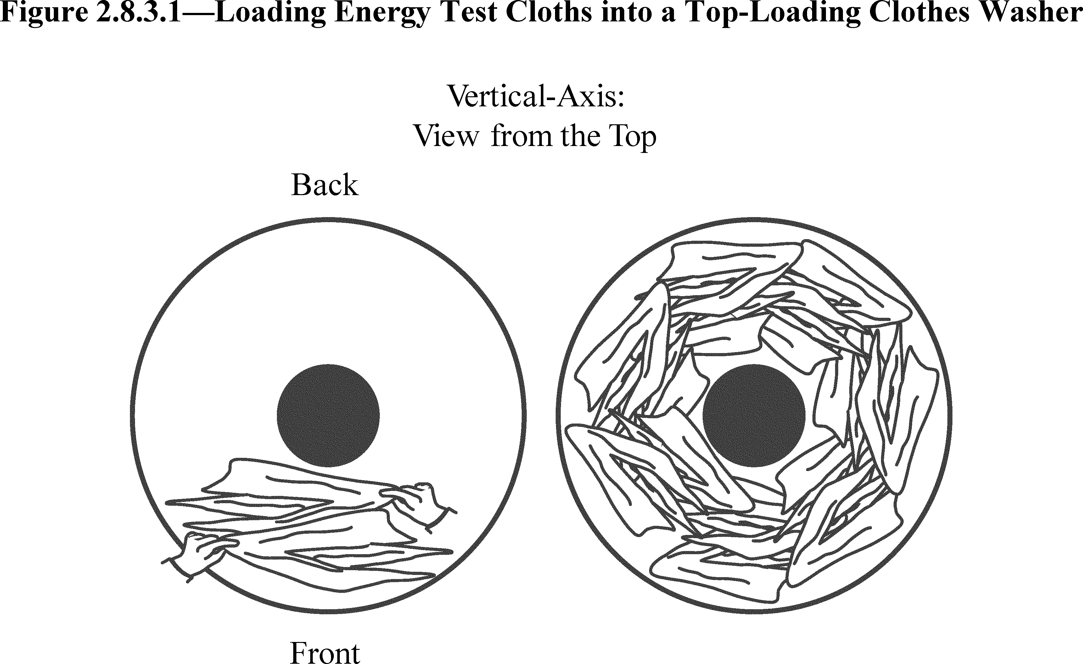
2.8.3.2 To load the energy test cloths in a front-loading clothes washer, grasp each test cloth in the center as indicated in section 2.8.3 of this appendix, and then place each cloth into the clothes container prior to activating the clothes washer.
2.9 Pre-conditioning.
2.9.1 Nonwater-heating clothes washer. If the clothes washer has not been filled with water in the preceding 96 hours, pre-condition it by running it through a cold rinse cycle and then draining it to ensure that the hose, pump, and sump are filled with water.
2.9.2 Water-heating clothes washer. If the clothes washer has not been filled with water in the preceding 96 hours, or if it has not been in the test room at the specified ambient conditions for 8 hours, pre-condition it by running it through a cold rinse cycle and then draining it to ensure that the hose, pump, and sump are filled with water.
2.10 Wash time setting. If one wash time is prescribed in the energy test cycle, that shall be the wash time setting; otherwise, the wash time setting shall be the higher of either the minimum or 70 percent of the maximum wash time available in the energy test cycle, regardless of the labeling of suggested dial locations. If 70% of the maximum wash time is not available on a dial with a discreet number of wash time settings, choose the next-highest setting greater than 70%. If the clothes washer is equipped with an electromechanical dial controlling wash time, reset the dial to the minimum wash time and then turn it in the direction of increasing wash time to reach the appropriate setting. If the appropriate setting is passed, return the dial to the minimum wash time and then turn in the direction of increasing wash time until the appropriate setting is reached.
2.11 Test room temperature for water-heating clothes washers. Maintain the test room ambient air temperature at 75 °F±5 °F (23.9 °C±2.8 °C).
3. Test Measurements
3.1 Clothes container capacity. Measure the entire volume which a dry clothes load could occupy within the clothes container during washer operation according to the following procedures:
3.1.1 Place the clothes washer in such a position that the uppermost edge of the clothes container opening is leveled horizontally, so that the container will hold the maximum amount of water. For front-loading clothes washers, the door seal and shipping bolts or other forms of bracing hardware to support the wash drum during shipping must remain in place during the capacity measurement.
If the design of a front-loading clothes washer does not include shipping bolts or other forms of bracing hardware to support the wash drum during shipping, a laboratory may support the wash drum by other means, including temporary bracing or support beams. Any temporary bracing or support beams must keep the wash drum in a fixed position, relative to the geometry of the door and door seal components, that is representative of the position of the wash drum during normal operation. The method used must avoid damage to the unit that would affect the results of the energy and water testing.
For a front-loading clothes washer that does not include shipping bolts or other forms of bracing hardware to support the wash drum during shipping, the test report must document the alternative method used to support the wash drum during capacity measurement, and, pursuant to § 429.71 of this chapter, the manufacturer must retain such documentation as part of its test records.
3.1.2 Line the inside of the clothes container with a 2 mil thickness (0.051 mm) plastic bag. All clothes washer components that occupy space within the clothes container and that are recommended for use during a wash cycle must be in place and must be lined with a 2 mil thickness (0.051 mm) plastic bag to prevent water from entering any void space.
3.1.3 Record the total weight of the machine before adding water.
3.1.4 Fill the clothes container manually with either 60 °F ± 5 °F (15.6 °C ± 2.8 °C) or 100 °F ± 10 °F (37.8 °C ± 5.5 °C) water to its uppermost edge. For a top-loading, vertical-axis clothes washer, the uppermost edge of the clothes container is defined as the highest point of the innermost diameter of the tub cover. Figure 3.1.4.1 illustrates the maximum fill level for top-loading vertical-axis clothes washers. Figure 3.1.4.2 shows the location of the maximum fill level for a variety of example tub cover designs.

For a front-loading horizontal-axis clothes washer, fill the clothes container to the highest point of contact between the door and the door gasket. If any portion of the door or gasket would occupy the measured volume space when the door is closed, exclude the volume that the door or gasket portion would occupy from the measurement. For a front-loading horizontal-axis clothes washer with a concave door shape, include any additional volume above the plane defined by the highest point of contact between the door and the door gasket, if that area can be occupied by clothing during washer operation. For a top-loading horizontal-axis clothes washer, include any additional volume above the plane of the door hinge that clothing could occupy during washer operation. Figure 3.1.4.3 illustrates the maximum fill volumes for all horizontal-axis clothes washer types.

For all clothes washers, exclude any volume that cannot be occupied by the clothing load during operation.
3.1.5 Measure and record the weight of water, W, in pounds. Calculate the clothes container capacity as follows:
C = W/d
where:
C = Capacity in cubic feet (liters).
W = Mass of water in pounds (kilograms).
d = Density of water (62.0 lbs/ft3 for 100 °F (993 kg/m3 for 37.8 °C) or 62.3 lbs/ft3 for 60 °F (998 kg/m3 for 15.6 °C)).
3.1.6 Calculate the clothes container capacity, C, to the nearest 0.01 cubic foot for the purpose of determining test load sizes per Table 5.1 of this appendix and for all subsequent calculations in this appendix that include the clothes container capacity.
3.2 Procedure for measuring water and energy consumption values on all automatic and semi-automatic washers. All energy consumption tests shall be performed under the energy test cycle(s), unless otherwise specified. Table 3.2 indicates the sections below that govern tests of particular clothes washers, based on the number of wash/rinse temperature selections available on the model and also, in some instances, method of water heating. The procedures prescribed are applicable regardless of a clothes washer's washing capacity, loading port location, primary axis of rotation of the clothes container, and type of control system. Data from a wash cycle that provides a visual or audio indicator to alert the user that an out-of-balance condition has been detected, or that terminates prematurely if an out-of-balance condition is detected, and thus does not include the agitation/tumble operation, spin speed(s), wash times, and rinse times applicable to the wash cycle under test, shall be discarded. The test report must document the rejection of data from any wash cycle during testing and the reason for the rejection.
3.2.1 Inlet water temperature and the wash/rinse temperature settings.
3.2.1.1 For automatic clothes washers set the wash/rinse temperature selection control to obtain the wash water temperature desired (extra hot, hot, warm, or cold) and cold rinse, and open both the hot and cold water faucets.
3.2.1.2 For semi-automatic washers:
(1) For hot water temperature, open the hot water faucet completely and close the cold water faucet;
(2) for warm inlet water temperature, open both hot and cold water faucets completely;
(3) for cold water temperature, close the hot water faucet and open the cold water faucet completely.
3.2.2 Total water consumption during the energy test cycle shall be measured, including hot and cold water consumption during wash, deep rinse, and spray rinse.
3.2.3 Clothes washers with automatic water fill/manual water fill control systems
3.2.3.1 Clothes washers with automatic water fill control system and alternate manual water fill control system. If a clothes washer with an automatic water fill control system allows user selection of manual controls as an alternative, then both manual and automatic modes shall be tested and, for each mode, the energy consumption (HET, MET, and DE) and water consumption (QT) values shall be calculated as set forth in section 4. Then the average of the two values (one from each mode, automatic and manual) for each variable shall be used in section 4 for the clothes washer.
3.2.3.2 Clothes washers with automatic water fill control system.
3.2.3.2.1. Not user adjustable. The maximum, minimum, and average water levels as defined in the following sections shall be interpreted to mean that amount of water fill which is selected by the control system when the respective test loads are used, as defined in Table 2.8. The load usage factors which shall be used when calculating energy consumption values are defined in Table 4.1.3.
3.2.3.2.2 User-adjustable. Four tests shall be conducted on clothes washers with user-adjustable automatic water fill controls that affect the relative wash water levels. The first test shall be conducted using the maximum test load and with the automatic water fill control system set in the setting that will give the most energy intensive result. The second test shall be conducted with the minimum test load and with the automatic water fill control system set in the setting that will give the least energy intensive result. The third test shall be conducted with the average test load and with the automatic water fill control system set in the setting that will give the most energy intensive result for the given test load. The fourth test shall be conducted with the average test load and with the automatic water fill control system set in the setting that will give the least energy intensive result for the given test load. The energy and water consumption for the average test load and water level shall be the average of the third and fourth tests.
3.2.3.3 Clothes washers with manual water fill control system. In accordance with Table 2.8, the water fill selector shall be set to the maximum water level available for the wash cycle under test for the maximum test load size and the minimum water level available for the wash cycle under test for the minimum test load size.
Table 3.2 - Test Section Reference
| Max. wash temp. available | ≤135 °F (57.2 °C) | >135 °F (57.2 °C)2 | |||
|---|---|---|---|---|---|
| Number of wash temp. Selections in the energy test cycle | 1 | 2 | >2 | 3 | >3 |
| Test Sections Required to be Followed | 3.3 | 3.3 | |||
| 3.4 | 3.4 | 3.4 | |||
| 3.5 | 3.5 | 3.5 | |||
| 3.6 | 3.6 | 3.6 | 3.6 | 3.6 | |
| 1 3.7 | 1 3.7 | 1 3.7 | 1 3.7 | 1 3.7 | |
| 3.8 | 3.8 | 3.8 | 3.8 | 3.8 | |
3.3 “Extra-Hot Wash” (Max Wash Temp >135 °F (57.2 °C)) for water heating clothes washers only. Water and electrical energy consumption shall be measured for each water fill level and/or test load size as specified in 3.3.1 through 3.3.3 for the hottest wash setting available.
Non-reversible temperature indicator labels, adhered to the inside of the clothes container, may be used to confirm that an extra-hot wash temperature greater than 135 °F has been achieved during the wash cycle, under the following conditions. The label must remain waterproof, intact, and adhered to the wash drum throughout an entire wash cycle; provide consistent maximum temperature readings; and provide repeatable temperature indications sufficient to demonstrate that a wash temperature of greater than 135 °F has been achieved. The label must have been verified to consistently indicate temperature measurements with an accuracy of ±1 °F if the label provides a temperature indicator at 135 °F. If the label does not provide a temperature indicator at 135 °F, the label must have been verified to consistently indicate temperature measurements with an accuracy of ±1 °F if the next-highest temperature indicator is greater than 135 °F and less than 140 °F, or ±3 °F if the next-highest temperature indicator is 140 °F or greater. If the label does not provide a temperature indicator at 135 °F, failure to activate the next-highest temperature indicator does not necessarily indicate the lack of an extra-hot wash temperature. However, such a result would not be considered a valid test due to the lack of verification of the water temperature requirement, in which case an alternative method must be used to confirm that an extra-hot wash temperature greater than 135 °F has been achieved during the wash cycle.
If using a temperature indicator label to test a front-loading clothes washer, adhere the label along the interior surface of the clothes container drum, midway between the front and the back of the drum, adjacent to one of the baffles. If using a temperature indicator label to test a top-loading clothes washer, adhere the label along the interior surface of the clothes container drum, on the vertical portion of the sidewall, as close to the bottom of the container as possible.
3.3.1 Maximum test load and water fill. Hot water consumption (Hmx), cold water consumption (Cmx), and electrical energy consumption (Emx) shall be measured for an extra hot wash/cold rinse energy test cycle, with the controls set for the maximum water fill level. The maximum test load size is to be used and shall be determined per Table 5.1.
3.3.2 Minimum test load and water fill. Hot water consumption (Hmn), cold water consumption (Cmn), and electrical energy consumption (Emn) shall be measured for an extra hot wash/cold rinse energy test cycle, with the controls set for the minimum water fill level. The minimum test load size is to be used and shall be determined per Table 5.1.
3.3.3 Average test load and water fill. For clothes washers with an automatic water fill control system, measure the values for hot water consumption (Hma), cold water consumption (Cma), and electrical energy consumption (Ema) for an extra-hot wash/cold rinse energy test cycle, with an average test load size as determined per Table 5.1.
3.4 “Hot Wash” (Max Wash Temp≤135 °F (57.2 °C)). Water and electrical energy consumption shall be measured for each water fill level or test load size as specified in 3.4.1 through 3.4.3 for a 135 °F (57.2 °C)) wash, if available, or for the hottest selection less than 135 °F (57.2 °C)).
3.4.1 Maximum test load and water fill. Hot water consumption (Hhx), cold water consumption (Chx), and electrical energy consumption (Ehx) shall be measured for a hot wash/cold rinse energy test cycle, with the controls set for the maximum water fill level. The maximum test load size is to be used and shall be determined per Table 5.1.
3.4.2 Minimum test load and water fill. Hot water consumption (Hhn), cold water consumption (Chn), and electrical energy consumption (Ehn) shall be measured for a hot wash/cold rinse energy test cycle, with the controls set for the minimum water fill level. The minimum test load size is to be used and shall be determined per Table 5.1.
3.4.3 Average test load and water fill. For clothes washers with an automatic water fill control system, measure the values for hot water consumption (Hha), cold water consumption (Cha), and electrical energy consumption (Eha) for a hot wash/cold rinse energy test cycle, with an average test load size as determined per Table 5.1.
3.5 “Warm Wash.” Water and electrical energy consumption shall be determined for each water fill level and/or test load size as specified in 3.5.1 through 3.5.3 for the applicable warm water wash temperature(s). For a clothes washer with fewer than four discrete warm wash selections, test all warm wash temperature selections. For a clothes washer that offers four or more warm wash selections, test at all discrete selections, or test at the 25 percent, 50 percent, and 75 percent positions of the temperature selection device between the hottest hot (≤135 °F (57.2 °C)) wash and the coldest cold wash. If a selection is not available at the 25, 50 or 75 percent position, in place of each such unavailable selection use the next warmer setting. Each reportable value to be used for the warm water wash setting shall be the arithmetic average of the results from all tests conducted pursuant to this section.
3.5.1 Maximum test load and water fill. Hot water consumption (Hwx), cold water consumption (Cwx), and electrical energy consumption (Ewx) shall be measured with the controls set for the maximum water fill level. The maximum test load size is to be used and shall be determined per Table 5.1.
3.5.2 Minimum test load and water fill. Hot water consumption (Hwn), cold water consumption (Cwn), and electrical energy consumption (Ewn) shall be measured with the controls set for the minimum water fill level. The minimum test load size is to be used and shall be determined per Table 5.1.
3.5.3 Average test load and water fill. For clothes washers with an automatic water fill control system, measure the values for hot water consumption (Hwa), cold water consumption (Cwa), and electrical energy consumption (Ewa) with an average test load size as determined per Table 5.1.
3.6 “Cold Wash” (Minimum Wash Temperature Selection). Water and electrical energy consumption shall be measured for each water fill level or test load size as specified in sections 3.6.1 through 3.6.3 of this appendix for the coldest wash temperature selection available. For a clothes washer that offers two or more wash temperature settings labeled as cold, such as “Cold” and “Tap Cold,” the setting with the minimum wash temperature shall be considered the cold wash. If any of the other cold wash temperature settings add hot water to raise the wash temperature above the cold water supply temperature, as defined in section 2.3 of this appendix, those setting(s) shall be considered warm wash setting(s), as defined in section 1.20 of this appendix. If none of the cold wash temperature settings add hot water for any of the water fill levels or test load sizes required for the energy test cycle, the wash temperature setting labeled as “Cold” shall be considered the cold wash, and the other wash temperature setting(s) labeled as cold shall not be required for testing.
3.6.1 Maximum test load and water fill. Hot water consumption (HcX), cold water consumption (CcX), and electrical energy consumption (EcX) shall be measured for a cold wash/cold rinse energy test cycle, with the controls set for the maximum water fill level. The maximum test load size is to be used and shall be determined per Table 5.1 of this appendix.
3.6.2 Minimum test load and water fill. Hot water consumption (Hcn), cold water consumption (Ccn), and electrical energy consumption (Ecn) shall be measured for a cold wash/cold rinse energy test cycle, with the controls set for the minimum water fill level. The minimum test load size is to be used and shall be determined per Table 5.1 of this appendix.
3.6.3 Average test load and water fill. For clothes washers with an automatic water fill control system, measure the values for hot water consumption (Hca), cold water consumption (Cca), and electrical energy consumption (Eca) for a cold wash/cold rinse energy test cycle, with an average test load size as determined per Table 5.1 of this appendix.
3.7 Warm Rinse. Tests in sections 3.7.1 and 3.7.2 shall be conducted with the hottest rinse temperature available. If multiple wash temperatures are available with the hottest rinse temperature, any “warm wash” temperature may be selected to conduct the tests.
3.7.1 For the rinse only, measure the amount of hot water consumed by the clothes washer including all deep and spray rinses, for the maximum (RX), minimum (Rn), and, if required by section 3.5.3 of this appendix, average (Ra) test load sizes or water fill levels.
3.7.2 Measure the amount of electrical energy consumed by the clothes washer to heat the rinse water only, including all deep and spray rinses, for the maximum (ERX), minimum (ERn), and, if required by section 3.5.3 of this appendix, average (ERa) test load sizes or water fill levels.
3.8 Remaining Moisture Content:
3.8.1 The wash temperature will be the same as the rinse temperature for all testing. Use the maximum test load as defined in Table 5.1 and section 3.1 for testing.
3.8.2 For clothes washers with cold rinse only:
3.8.2.1 Record the actual ‘bone dry’ weight of the test load (WImax), then place the test load in the clothes washer.
3.8.2.2 Set water level selector to maximum fill.
3.8.2.3 Run the energy test cycle.
3.8.2.4 Record the weight of the test load immediately after completion of the energy test cycle (WCmax).
3.8.2.5 Calculate the remaining moisture content of the maximum test load, RMCMAX, expressed as a percentage and defined as:
RMCmax = ((WCmax−WImax)/WImax) × 100%
3.8.3 For clothes washers with cold and warm rinse options:
3.8.3.1 Complete steps 3.8.2.1 through 3.8.2.4 for cold rinse. Calculate the remaining moisture content of the maximum test load for cold rinse, RMCCOLD, expressed as a percentage and defined as:
RMCCOLD = ((WCmax−WImax)/WImax) × 100%
3.8.3.2 Complete steps 3.8.2.1 through 3.8.2.4 for warm rinse. Calculate the remaining moisture content of the maximum test load for warm rinse, RMCWARM, expressed as a percentage and defined as:
RMCWARM = ((WCmax − WImax)/WImax) × 100%
3.8.3.3 Calculate the remaining moisture content of the maximum test load, RMCmax, expressed as a percentage and defined as:
RMCmax = RMCCOLD × (1-TUFr) + RMCWARM × (TUFr).
where:
TUFr is the temperature use factor for warm rinse as defined in Table 4.1.1.
3.8.4 Clothes washers which have options that result in different RMC values, such as multiple selection of spin speeds or spin times, that are available in the energy test cycle, shall be tested at the maximum and minimum extremes of the available options, excluding any “no spin” (zero spin speed) settings, in accordance with requirements in 3.8.2 or 3.8.3. The calculated RMCmax extraction and RMCmin extraction at the maximum and minimum settings, respectively, shall be combined as follows and the final RMC to be used in section 4.3 shall be:
RMC = 0.75 × RMCmax extraction + 0.25 × RMCmin extraction
3.8.5 The procedure for calculating RMC as defined in section 3.8.2.5, 3.8.3.3., or 3.8.4 of this appendix may be replicated twice in its entirety, for a total of three independent RMC measurements. If three replications of the RMC measurement are performed, use the average of the three RMC measurements as the final RMC in section 4.3 of this appendix.
4. Calculation of Derived Results From Test Measurements
4.1 Hot water and machine electrical energy consumption of clothes washers.
4.1.1 Per-cycle temperature-weighted hot water consumption for maximum, average, and minimum water fill levels using each appropriate load size as defined in section 2.8 and Table 5.1. Calculate for the cycle under test the per-cycle temperature weighted hot water consumption for the maximum water fill level, Vhx, the average water fill level, Vha, and the minimum water fill level, Vhn, expressed in gallons per cycle (or liters per cycle) and defined as:
(a) Vhx = [Hmx × TUFm] + [Hhx × TUFh] + [Hwx × TUFw] + [Hcx × TUFc] + [Rx × TUFr]
(b) Vha = [Hma × TUFm] + [Hha × TUFh] + [Hwa × TUFw] + [Hca × TUFc] + [Ra × TUFr]
(c) Vhn = [Hmn × TUFm] + [Hhn × TUFh] + [Hwn × TUFw] + [Hcn × TUFc] + [Rn × TUFr]
where:
Hmx, Hma, and Hmn, are reported hot water consumption values, in gallons per-cycle (or liters per cycle), at maximum, average, and minimum water fill, respectively, for the extra-hot wash cycle with the appropriate test loads as defined in section 2.8.
Hhx, Hha, and Hhn, are reported hot water consumption values, in gallons per-cycle (or liters per cycle), at maximum, average, and minimum water fill, respectively, for the hot wash cycle with the appropriate test loads as defined in section 2.8.
Hwx, Hwa, and Hwn, are reported hot water consumption values, in gallons per-cycle (or liters per cycle), at maximum, average, and minimum water fill, respectively, for the warm wash cycle with the appropriate test loads as defined in section 2.8.
Hcx, Hca, and Hcn, are reported hot water consumption values, in gallons per-cycle (or liters per cycle), at maximum, average, and minimum water fill, respectively, for the cold wash cycle with the appropriate test loads as defined in section 2.8.
Rx, Ra, and Rn are the reported hot water consumption values, in gallons per-cycle (or liters per cycle), at maximum, average, and minimum water fill, respectively, for the warm rinse cycle and the appropriate test loads as defined in section 2.8.
TUFm, TUFh, TUFw, TUFc, and TUFr are temperature use factors for extra hot wash, hot wash, warm wash, cold wash, and warm rinse temperature selections, respectively, and are as defined in Table 4.1.1.
Table 4.1.1 - Temperature Use Factors
| Max Wash Temp Available | ≤135 °F | ≤135 °F | ≤135 °F | >135 °F | >135 °F |
| (57.2 °C) | (57.2 °C) | (57.2 °C) | (57.2 °C) | (57.2 °C) | |
| No. Wash Temp Selections | Single | 2 Temps | >2 Temps | 3 Temps | >3 Temps |
| TUFm (extra hot) | NA | NA | NA | 0.14 | 0.05 |
| TUFh (hot) | NA | 0.63 | 0.14 | NA | 0.09 |
| TUFw (warm) | NA | NA | 0.49 | 0.49 | 0.49 |
| TUFc (cold) | 1.00 | 0.37 | 0.37 | 0.37 | 0.37 |
| TUFr (warm rinse) | 0.27 | 0.27 | 0.27 | 0.27 | 0.27 |
4.1.2 Total per-cycle hot water energy consumption for all maximum, average, and minimum water fill levels tested. Calculate the total per-cycle hot water energy consumption for the maximum water fill level, HEmax, the minimum water fill level, HEmin, and the average water fill level, HEavg, expressed in kilowatt-hours per cycle and defined as:
(a) HEmax = [Vhx × T × K] = Total energy when a maximum load is tested.
(b) HEavg = [Vha × T × K] = Total energy when an average load is tested.
(c) HEmin = [Vhn × T × K] = Total energy when a minimum load is tested.
where:
T = Temperature rise = 75 °F (41.7 °C).
K = Water specific heat in kilowatt-hours per gallon degree F = 0.00240 (0.00114 kWh/L-°C).
Vhx Vha, and Vhn, are as defined in 4.1.1.
4.1.3 Total weighted per-cycle hot water energy consumption. Calculate the total weighted per cycle hot water energy consumption, HET, expressed in kilowatt-hours per cycle and defined as:
HET = [HEmax × Fmax] + [HEavg × Favg] + [HEmn × Fmin]
where:
HEmax, HEavg, and HEmin are as defined in 4.1.2.
Fmax, Favg, and Fmin are the load usage factors for the maximum, average, and minimum test loads based on the size and type of control system on the washer being tested. The values are as shown in table 4.1.3.
Table 4.1.3 - Load Usage Factors
| Load usage factor | Water fill control system | |
|---|---|---|
| Manual | Automatic | |
| Fmax = | 0.721 | 0.122 |
| Favg = | 0.742 | |
| Fmin = | 0.281 | 0.142 |
4.1.4 Total per-cycle hot water energy consumption using gas-heated or oil-heated water, for product labeling requirements. Calculate for the energy test cycle the per-cycle hot water consumption, HETG, using gas-heated or oil-heated water, expressed in Btu per cycle (or megajoules per cycle) and defined as:
HETG = HET × 1/e × 3412 Btu/kWh or HETG = HET × 1/e × 3.6 MJ/kWh
where:
e = Nominal gas or oil water heater efficiency = 0.75.
HET = As defined in 4.1.3.
4.1.5 Per-cycle machine electrical energy consumption for all maximum, average, and minimum test load sizes. Calculate the total per-cycle machine electrical energy consumption for the maximum water fill level, MEmax, the minimum water fill level, MEmin, and the average water fill level, MEavg, expressed in kilowatt-hours per cycle and defined as:
(a) MEmax = [Emx × TUFm] + [Ehx × TUFh] + [Ewx × TUFw] + [Ecx × TUFc] + [ERx × TUFr]
(b) MEavg = [Ema × TUFm] + [Eha × TUFh] + [Ewa × TUFw] + [Eca × TUFc] + [ERa × TUFr]
(c) MEmin = [Emn × TUFm] + [Ehn × TUFh] + [Ewn × TUFw] + [Ecn × xTUFc] + [ERn × TUFr]
where:
Emx, Ema, and Emn, are reported electrical energy consumption values, in kilowatt-hours per cycle, at maximum, average, and minimum test loads, respectively, for the extra-hot wash cycle.
Ehx, Eha, and Ehn, are reported electrical energy consumption values, in kilowatt-hours per cycle, at maximum, average, and minimum test loads, respectively, for the hot wash cycle.
Ewx, Ewa, and Ewn, are reported electrical energy consumption values, in kilowatt-hours per cycle, at maximum, average, and minimum test loads, respectively, for the warm wash cycle.
Ecx, Eca, and Ecn, are reported electrical energy consumption values, in kilowatt-hours per cycle, at maximum, average, and minimum test loads, respectively, for the cold wash cycle.
ERx, ERa, ERn, are reported electrical energy consumption values, in kilowatt-hours per cycle, at maximum, average, and minimum test loads, respectively, for the warm rinse cycle per definitions in 3.7.2 of this appendix.
TUFm, TUFh, TUFw, TUFc, and TUFr are as defined in Table 4.1.1.
4.1.6 Total weighted per-cycle machine electrical energy consumption. Calculate the total per cycle load size weighted energy consumption, MET, expressed in kilowatt-hours per cycle and defined as:
MET = [MEmax × Fmax] + [MEavg × Favg] + [MEmin × Fmin]
where:
MEmax, MEavg, and MEmin are as defined in 4.1.5.
Fmax, Favg, and Fmin are as defined in Table 4.1.3.
4.1.7 Total per-cycle energy consumption when electrically heated water is used. Calculate for the energy test cycle the total per-cycle energy consumption, ETE, using electrical heated water, expressed in kilowatt-hours per cycle and defined as:
ETE = HET + MET
where:
MET = As defined in 4.1.6.
HET = As defined in 4.1.3.
4.2 Water consumption of clothes washers.
4.2.1 Per-cycle water consumption. Calculate the maximum, average, and minimum total water consumption, expressed in gallons per cycle (or liters per cycle), for the cold wash/cold rinse cycle and defined as:
Qmax = [Hcx + Ccx]
Qavg = [Hca + Cca]
Qmin = [Hcn + Ccn]
where:
Hcx, Ccx, Hca, Cca, Hcn, and Ccn are as defined in 3.6.
4.2.2 Total weighted per-cycle water consumption. Calculate the total weighted per cycle consumption, QT, expressed in gallons per cycle (or liters per cycle) and defined as:
QT = [Qmax × Fmax] + [Qavg × Favg] + [Qmin × Fmin]
where:
Qmax, Qavg, and Qmin are as defined in 4.2.1.
Fmax, Favg, and Fmin are as defined in table 4.1.3.
4.2.3 Water factor. Calculate the water factor, WF, expressed in gallons per cycle per cubic foot (or liters per cycle per liter), as:
WF = QT/C
where:
QT = As defined in section 4.2.2 of this appendix.
C = As defined in section 3.1.6 of this appendix.
4.3 Per-cycle energy consumption for removal of moisture from test load. Calculate the per-cycle energy required to remove the moisture of the test load, DE, expressed in kilowatt-hours per cycle and defined as
DE = (LAF) × (Maximum test load weight) × (RMC - 4%) × (DEF) × (DUF)
where:
LAF = Load adjustment factor = 0.52.
Test load weight = As required in 3.8.1, expressed in lbs/cycle.
RMC = As defined in 3.8.2.5, 3.8.3.3 or 3.8.4.
DEF= nominal energy required for a clothes dryer to remove moisture from clothes = 0.5 kWh/lb (1.1 kWh/kg).
DUF = dryer usage factor, percentage of washer loads dried in a clothes dryer = 0.84.
4.4 Modified energy factor. Calculate the modified energy factor, MEF, expressed in cubic feet per kilowatt-hour per cycle (or liters per kilowatt-hour per cycle) and defined as:
MEF = C/(ETE + DE)
where:
C = As defined in section 3.1.6 of this appendix.
ETE = As defined in section 4.1.7 of this appendix.
DE = As defined in section 4.3 of this appendix.
5. Test Loads
Table 5.1 - Test Load Sizes
| Container volume | Minimum load | Maximum load | Average load | ||||
|---|---|---|---|---|---|---|---|
| cu. ft.
≥< |
liter
≥< |
lb | kg | lb | kg | lb | kg |
| 0-0.80 | 0-22.7 | 3.00 | 1.36 | 3.00 | 1.36 | 3.00 | 1.36 |
| 0.80-0.90 | 22.7-25.5 | 3.00 | 1.36 | 3.50 | 1.59 | 3.25 | 1.47 |
| 0.90-1.00 | 25.5-28.3 | 3.00 | 1.36 | 3.90 | 1.77 | 3.45 | 1.56 |
| 1.00-1.10 | 28.3-31.1 | 3.00 | 1.36 | 4.30 | 1.95 | 3.65 | 1.66 |
| 1.10-1.20 | 31.1-34.0 | 3.00 | 1.36 | 4.70 | 2.13 | 3.85 | 1.75 |
| 1.20-1.30 | 34.0-36.8 | 3.00 | 1.36 | 5.10 | 2.31 | 4.05 | 1.84 |
| 1.30-1.40 | 36.8-39.6 | 3.00 | 1.36 | 5.50 | 2.49 | 4.25 | 1.93 |
| 1.40-1.50 | 39.6-42.5 | 3.00 | 1.36 | 5.90 | 2.68 | 4.45 | 2.02 |
| 1.50-1.60 | 42.5-45.3 | 3.00 | 1.36 | 6.40 | 2.90 | 4.70 | 2.13 |
| 1.60-1.70 | 45.3-48.1 | 3.00 | 1.36 | 6.80 | 3.08 | 4.90 | 2.22 |
| 1.70-1.80 | 48.1-51.0 | 3.00 | 1.36 | 7.20 | 3.27 | 5.10 | 2.31 |
| 1.80-1.90 | 51.0-53.8 | 3.00 | 1.36 | 7.60 | 3.45 | 5.30 | 2.40 |
| 1.90-2.00 | 53.8-56.6 | 3.00 | 1.36 | 8.00 | 3.63 | 5.50 | 2.49 |
| 2.00-2.10 | 56.6-59.5 | 3.00 | 1.36 | 8.40 | 3.81 | 5.70 | 2.59 |
| 2.10-2.20 | 59.5-62.3 | 3.00 | 1.36 | 8.80 | 3.99 | 5.90 | 2.68 |
| 2.20-2.30 | 62.3-65.1 | 3.00 | 1.36 | 9.20 | 4.17 | 6.10 | 2.77 |
| 2.30-2.40 | 65.1-68.0 | 3.00 | 1.36 | 9.60 | 4.35 | 6.30 | 2.86 |
| 2.40-2.50 | 68.0-70.8 | 3.00 | 1.36 | 10.00 | 4.54 | 6.50 | 2.95 |
| 2.50-2.60 | 70.8-73.6 | 3.00 | 1.36 | 10.50 | 4.76 | 6.75 | 3.06 |
| 2.60-2.70 | 73.6-76.5 | 3.00 | 1.36 | 10.90 | 4.94 | 6.95 | 3.15 |
| 2.70-2.80 | 76.5-79.3 | 3.00 | 1.36 | 11.30 | 5.13 | 7.15 | 3.24 |
| 2.80-2.90 | 79.3-82.1 | 3.00 | 1.36 | 11.70 | 5.31 | 7.35 | 3.33 |
| 2.90-3.00 | 82.1-85.0 | 3.00 | 1.36 | 12.10 | 5.49 | 7.55 | 3.42 |
| 3.00-3.10 | 85.0-87.8 | 3.00 | 1.36 | 12.50 | 5.67 | 7.75 | 3.52 |
| 3.10-3.20 | 87.8-90.6 | 3.00 | 1.36 | 12.90 | 5.85 | 7.95 | 3.61 |
| 3.20-3.30 | 90.6-93.4 | 3.00 | 1.36 | 13.30 | 6.03 | 8.15 | 3.70 |
| 3.30-3.40 | 93.4-96.3 | 3.00 | 1.36 | 13.70 | 6.21 | 8.35 | 3.79 |
| 3.40-3.50 | 96.3-99.1 | 3.00 | 1.36 | 14.10 | 6.40 | 8.55 | 3.88 |
| 3.50-3.60 | 99.1-101.9 | 3.00 | 1.36 | 14.60 | 6.62 | 8.80 | 3.99 |
| 3.60-3.70 | 101.9-104.8 | 3.00 | 1.36 | 15.00 | 6.80 | 9.00 | 4.08 |
| 3.70-3.80 | 104.8-107.6 | 3.00 | 1.36 | 15.40 | 6.99 | 9.20 | 4.17 |
| 3.80-3.90 | 107.6-110.4 | 3.00 | 1.36 | 15.80 | 7.16 | 9.40 | 4.26 |
| 3.90-4.00 | 110.4-113.3 | 3.00 | 1.36 | 16.20 | 7.34 | 9.60 | 4.35 |
| 4.00-4.10 | 113.3-116.1 | 3.00 | 1.36 | 16.60 | 7.53 | 9.80 | 4.45 |
| 4.10-4.20 | 116.1-118.9 | 3.00 | 1.36 | 17.00 | 7.72 | 10.00 | 4.54 |
| 4.20-4.30 | 118.9-121.8 | 3.00 | 1.36 | 17.40 | 7.90 | 10.20 | 4.63 |
| 4.30-4.40 | 121.8-124.6 | 3.00 | 1.36 | 17.80 | 8.09 | 10.40 | 4.72 |
| 4.40-4.50 | 124.6-127.4 | 3.00 | 1.36 | 18.20 | 8.27 | 10.60 | 4.82 |
| 4.50-4.60 | 127.4-130.3 | 3.00 | 1.36 | 18.70 | 8.46 | 10.85 | 4.91 |
| 4.60-4.70 | 130.3-133.1 | 3.00 | 1.36 | 19.10 | 8.65 | 11.05 | 5.00 |
| 4.70-4.80 | 133.1-135.9 | 3.00 | 1.36 | 19.50 | 8.83 | 11.25 | 5.10 |
| 4.80-4.90 | 135.9-138.8 | 3.00 | 1.36 | 19.90 | 9.02 | 11.45 | 5.19 |
| 4.90-5.00 | 138.8-141.6 | 3.00 | 1.36 | 20.30 | 9.20 | 11.65 | 5.28 |
| 5.00-5.10 | 141.6-144.4 | 3.00 | 1.36 | 20.70 | 9.39 | 11.85 | 5.38 |
| 5.10-5.20 | 144.4-147.2 | 3.00 | 1.36 | 21.10 | 9.58 | 12.05 | 5.47 |
| 5.20-5.30 | 147.2-150.1 | 3.00 | 1.36 | 21.50 | 9.76 | 12.25 | 5.56 |
| 5.30-5.40 | 150.1-152.9 | 3.00 | 1.36 | 21.90 | 9.95 | 12.45 | 5.65 |
| 5.40-5.50 | 152.9-155.7 | 3.00 | 1.36 | 22.30 | 10.13 | 12.65 | 5.75 |
| 5.50-5.60 | 155.7-158.6 | 3.00 | 1.36 | 22.80 | 10.32 | 12.90 | 5.84 |
| 5.60-5.70 | 158.6-161.4 | 3.00 | 1.36 | 23.20 | 10.51 | 13.10 | 5.93 |
| 5.70-5.80 | 161.4-164.2 | 3.00 | 1.36 | 23.60 | 10.69 | 13.30 | 6.03 |
| 5.80-5.90 | 164.2-167.1 | 3.00 | 1.36 | 24.00 | 10.88 | 13.50 | 6.12 |
| 5.90-6.00 | 167.1-169.9 | 3.00 | 1.36 | 24.40 | 11.06 | 13.70 | 6.21 |
6. Waivers and Field Testing
6.1 Waivers and Field Testing for Non-conventional Clothes Washers. Manufacturers of nonconventional clothes washers, such as clothes washers with adaptive control systems, must submit a petition for waiver pursuant to 10 CFR 430.27 to establish an acceptable test procedure for that clothes washer. For these and other clothes washers that have controls or systems such that the DOE test procedures yield results that are so unrepresentative of the clothes washer's true energy consumption characteristics as to provide materially inaccurate comparative data, field testing may be appropriate for establishing an acceptable test procedure. The following are guidelines for field testing which may be used by manufacturers in support of petitions for waiver. These guidelines are not mandatory and the Department may determine that they do not apply to a particular model. Depending upon a manufacturer's approach for conducting field testing, additional data may be required. Manufacturers are encouraged to communicate with the Department prior to the commencement of field tests which may be used to support a petition for waiver. Section 6.3 provides an example of field testing for a clothes washer with an adaptive water fill control system. Other features, such as the use of various spin speed selections, could be the subject of field tests.
6.2 Nonconventional Wash System Energy Consumption Test. The field test may consist of a minimum of 10 of the nonconventional clothes washers (“test clothes washers”) and 10 clothes washers already being distributed in commerce (“base clothes washers”). The tests should include a minimum of 50 energy test cycles per clothes washer. The test clothes washers and base clothes washers should be identical in construction except for the controls or systems being tested. Equal numbers of both the test clothes washer and the base clothes washer should be tested simultaneously in comparable settings to minimize seasonal or consumer laundering conditions or variations. The clothes washers should be monitored in such a way as to accurately record the average total energy and water consumption per cycle, including water heating energy when electrically heated water is used, and the energy required to remove the remaining moisture of the test load. The field test results should be used to determine the best method to correlate the rating of the test clothes washer to the rating of the base clothes washer.
6.3 Adaptive water fill control system field test. Section 3.2.3.1 defines the test method for measuring energy consumption for clothes washers which incorporate control systems having both adaptive and alternate cycle selections. Energy consumption calculated by the method defined in section 3.2.3.1 assumes the adaptive cycle will be used 50 percent of the time. This section can be used to develop field test data in support of a petition for waiver when it is believed that the adaptive cycle will be used more than 50 percent of the time. The field test sample size should be a minimum of 10 test clothes washers. The test clothes washers should be totally representative of the design, construction, and control system that will be placed in commerce. The duration of field testing in the user's house should be a minimum of 50 energy test cycles, for each unit. No special instructions as to cycle selection or product usage should be given to the field test participants, other than inclusion of the product literature pack which would be shipped with all units, and instructions regarding filling out data collection forms, use of data collection equipment, or basic procedural methods. Prior to the test clothes washers being installed in the field test locations, baseline data should be developed for all field test units by conducting laboratory tests as defined by section 1 through section 5 of these test procedures to determine the energy consumption, water consumption, and remaining moisture content values. The following data should be measured and recorded for each wash load during the test period: wash cycle selected, the mode of the clothes washer (adaptive or manual), clothes load dry weight (measured after the clothes washer and clothes dryer cycles are completed) in pounds, and type of articles in the clothes load (e.g., cottons, linens, permanent press). The wash loads used in calculating the in-home percentage split between adaptive and manual cycle usage should be only those wash loads which conform to the definition of the energy test cycle.
Calculate:
T = The total number of energy test cycles run during the field test
Ta = The total number of adaptive control energy test cycles
Tm = The total number of manual control energy test cycles
The percentage weighting factors:
Pa = (Ta/T) × 100 (the percentage weighting for adaptive control selection)
Pm = (Tm/T) × 100 (the percentage weighting for manual control selection)
Energy consumption (HET, MET, and DE) and water consumption (QT), values calculated in section 4 for the manual and adaptive modes, should be combined using Pa and Pm as the weighting factors.
[62 FR 45508, Aug. 27, 1997; 63 FR 16669, Apr. 6, 1998, as amended at 66 FR 3330, Jan. 12, 2001; 68 FR 62204, Oct. 31, 2003; 69 FR 18803, Apr. 9, 2004; 77 FR 13937, Mar. 7, 2012; 77 FR 20292, Apr. 4, 2012; 80 FR 46760, Aug. 5, 2015; 80 FR 62442, Oct. 16, 2015]
Appendix J2 to Subpart B of Part 430 - Uniform Test Method for Measuring the Energy Consumption of Automatic and Semi-automatic Clothes Washers
Any representation related to the energy or water consumption of residential clothes washers must be based upon results generated using Appendix J2. Specifically, before February 1, 2016, representations must be based upon results generated either under this appendix or under Appendix J2 as it appeared in the 10 CFR parts 200-499 edition revised as of January 1, 2015. Any representations made on or after February 1, 2016 must be made based upon results generated using this appendix.
Before January 1, 2018, any representation related to the energy or water consumption of commercial clothes washers must be based on results generated using Appendix J1. Any representations made on or after January 1, 2018, must be based upon results generated using Appendix J2.
1. Definitions and Symbols
1.1 Active mode means a mode in which the clothes washer is connected to a mains power source, has been activated, and is performing one or more of the main functions of washing, soaking, tumbling, agitating, rinsing, and/or removing water from the clothing, or is involved in functions necessary for these main functions, such as admitting water into the washer or pumping water out of the washer. Active mode also includes delay start and cycle finished modes.
1.2 Active washing mode means a mode in which the clothes washer is performing any of the operations included in a complete cycle intended for washing a clothing load, including the main functions of washing, soaking, tumbling, agitating, rinsing, and/or removing water from the clothing.
1.3 Adaptive control system means a clothes washer control system, other than an adaptive water fill control system, that is capable of automatically adjusting washer operation or washing conditions based on characteristics of the clothes load placed in the clothes container, without allowing or requiring user intervention or actions. The automatic adjustments may, for example, include automatic selection, modification, or control of any of the following: wash water temperature, agitation or tumble cycle time, number of rinse cycles, or spin speed. The characteristics of the clothes load, which could trigger such adjustments, could, for example, consist of or be indicated by the presence of either soil, soap, suds, or any other additive laundering substitute or complementary product.
1.4 Adaptive water fill control system means a clothes washer automatic water fill control system that is capable of automatically adjusting the water fill level based on the size or weight of the clothes load placed in the clothes container.
1.5 Automatic water fill control system means a clothes washer water fill control system that does not allow or require the user to determine or select the water fill level, and includes adaptive water fill control systems and fixed water fill control systems.
1.6 Bone-dry means a condition of a load of test cloth that has been dried in a dryer at maximum temperature for a minimum of 10 minutes, removed and weighed before cool down, and then dried again for 10 minute periods until the final weight change of the load is 1 percent or less.
1.7 Clothes container means the compartment within the clothes washer that holds the clothes during the operation of the machine.
1.8 Cold rinse means the coldest rinse temperature available on the machine, as indicated to the user on the clothes washer control panel.
1.9 Combined low-power mode means the aggregate of available modes other than active washing mode, including inactive mode, off mode, delay start mode, and cycle finished mode.
1.10 Compact means a clothes washer that has a clothes container capacity of less than 1.6 ft3 (45 L).
1.11 Cycle finished mode means an active mode that provides continuous status display, intermittent tumbling, or air circulation following operation in active washing mode.
1.12 Delay start mode means an active mode in which activation of active washing mode is facilitated by a timer.
1.13 Energy test cycle means the complete set of wash/rinse temperature selections required for testing, as determined according to section 2.12. Within the energy test cycle, the following definitions apply:
(a) Cold Wash/Cold Rinse is the wash/rinse temperature selection determined by evaluating the flowchart in Figure 2.12.1 of this appendix.
(b) Hot Wash/Cold Rinse is the wash/rinse temperature selection determined by evaluating the flowchart in Figure 2.12.2 of this appendix.
(c) Warm Wash/Cold Rinse is the wash/rinse temperature selection determined by evaluating the flowchart in Figure 2.12.3 of this appendix.
(d) Warm Wash/Warm Rinse is the wash/rinse temperature selection determined by evaluating the flowchart in Figure 2.12.4 of this appendix.
(e) Extra-Hot Wash/Cold Rinse is the wash/rinse temperature selection determined by evaluating the flowchart in Figure 2.12.5 of this appendix.
1.14 Fixed water fill control system means a clothes washer automatic water fill control system that automatically terminates the fill when the water reaches an appropriate level in the clothes container.
1.15 IEC 62301 means the test standard published by the International Electrotechnical Commission, entitled “Household electrical appliances - Measurement of standby power,” Publication 62301, Edition 2.0 2011-01 (incorporated by reference; see § 430.3).
1.16 Inactive mode means a standby mode that facilitates the activation of active mode by remote switch (including remote control), internal sensor, or timer, or that provides continuous status display.
1.17 Integrated modified energy factor means the quotient of the cubic foot (or liter) capacity of the clothes container divided by the total clothes washer energy consumption per cycle, with such energy consumption expressed as the sum of:
(a) The machine electrical energy consumption;
(b) The hot water energy consumption;
(c) The energy required for removal of the remaining moisture in the wash load; and
(d) The combined low-power mode energy consumption.
1.18 Integrated water factor means the quotient of the total weighted per-cycle water consumption for all wash cycles in gallons divided by the cubic foot (or liter) capacity of the clothes washer.
1.19 Load usage factor means the percentage of the total number of wash loads that a user would wash a particular size (weight) load.
1.20 Lot means a quantity of cloth that has been manufactured with the same batches of cotton and polyester during one continuous process.
1.21 Manual control system means a clothes washer control system that requires that the user make the choices that determine washer operation or washing conditions, such as, for example, wash/rinse temperature selections and wash time, before starting the cycle.
1.22 Manual water fill control system means a clothes washer water fill control system that requires the user to determine or select the water fill level.
1.23 Modified energy factor means the quotient of the cubic foot (or liter) capacity of the clothes container divided by the total clothes washer energy consumption per cycle, with such energy consumption expressed as the sum of the machine electrical energy consumption, the hot water energy consumption, and the energy required for removal of the remaining moisture in the wash load.
1.24 Non-water-heating clothes washer means a clothes washer that does not have an internal water heating device to generate hot water.
1.25 Normal cycle means the cycle recommended by the manufacturer (considering manufacturer instructions, control panel labeling, and other markings on the clothes washer) for normal, regular, or typical use for washing up to a full load of normally-soiled cotton clothing. For machines where multiple cycle settings are recommended by the manufacturer for normal, regular, or typical use for washing up to a full load of normally-soiled cotton clothing, then the Normal cycle is the cycle selection that results in the lowest IMEF or MEF value.
1.26 Off mode means a mode in which the clothes washer is connected to a mains power source and is not providing any active or standby mode function, and where the mode may persist for an indefinite time.
1.27 Roll means a subset of a lot.
1.28 Standard means a clothes washer that has a clothes container capacity of 1.6 ft3 (45 L) or greater.
1.29 Standby mode means any mode in which the clothes washer is connected to a mains power source and offers one or more of the following user oriented or protective functions that may persist for an indefinite time:
(a) Facilitating the activation of other modes (including activation or deactivation of active mode) by remote switch (including remote control), internal sensor, or timer;
(b) Continuous functions, including information or status displays (including clocks) or sensor-based functions.
A timer is a continuous clock function (which may or may not be associated with a display) that provides regular scheduled tasks (e.g., switching) and that operates on a continuous basis.
1.30 Symbol usage. The following identity relationships are provided to help clarify the symbology used throughout this procedure.
C - Capacity
C (with subscripts) - Cold Water Consumption
D - Energy Consumption for Removal of Moisture from Test Load
E - Electrical Energy Consumption
F - Load Usage Factor
H - Hot Water Consumption
HE - Hot Water Energy Consumption
ME - Machine Electrical Energy Consumption
P - Power
Q - Water Consumption
RMC - Remaining Moisture Content
S - Annual Hours
TUF - Temperature Use Factor
V - Temperature-Weighted Hot Water Consumption
W - Mass of Water
WC - Weight of Test Load After Extraction
WI - Initial Weight of Dry Test Load
Subscripts:
a or avg - Average Test Load
c - Cold Wash (minimum wash temp.)
corr - Corrected (RMC values)
h - Hot Wash (maximum wash temp. ≤135 °F (57.2 °C))
ia - Inactive Mode
LP - Combined Low-Power Mode
m - Extra-Hot Wash (maximum wash temp. >135 °F (57.2 °C))
n - Minimum Test Load
o - Off Mode
oi - Combined Off and Inactive Modes
T - Total
w - Warm Wash
ww - Warm Wash/Warm Rinse
x - Maximum Test Load
The following examples are provided to show how the above symbols can be used to define variables:
EmX = “Electrical Energy Consumption” for an “Extra-Hot Wash” and “Maximum Test Load”
HEmin = “Hot Water Energy Consumption” for the “Minimum Test Load”
Qhmin = “Water Consumption” for a “Hot Wash” and “Minimum Test Load”
TUFm = “Temperature Use Factor” for an “Extra-Hot Wash”
1.31 Temperature use factor means, for a particular wash/rinse temperature setting, the percentage of the total number of wash loads that an average user would wash with that setting.
1.32 Thermostatically controlled water valves means clothes washer controls that have the ability to sense and adjust the hot and cold supply water.
1.33 Water factor means the quotient of the total weighted per-cycle water consumption for cold wash divided by the cubic foot (or liter) capacity of the clothes washer.
1.34 Water-heating clothes washer means a clothes washer where some or all of the hot water for clothes washing is generated by a water heating device internal to the clothes washer.
2. Testing Conditions
2.1 Electrical energy supply.
2.1.1 Supply voltage and frequency. Maintain the electrical supply at the clothes washer terminal block within 2 percent of 120, 120/240, or 120/208Y volts as applicable to the particular terminal block wiring system and within 2 percent of the nameplate frequency as specified by the manufacturer. If the clothes washer has a dual voltage conversion capability, conduct test at the highest voltage specified by the manufacturer.
2.1.2 Supply voltage waveform. For the combined low-power mode testing, maintain the electrical supply voltage waveform indicated in Section 4, Paragraph 4.3.2 of IEC 62301. If the power measuring instrument used for testing is unable to measure and record the total harmonic content during the test measurement period, total harmonic content may be measured and recorded immediately before and after the test measurement period.
2.2 Supply water. Maintain the temperature of the hot water supply at the water inlets between 130 °F (54.4 °C) and 135 °F (57.2 °C), using 135 °F as the target temperature. Maintain the temperature of the cold water supply at the water inlets between 55 °F (12.8 °C) and 60 °F (15.6 °C), using 60 °F as the target temperature.
2.3 Water pressure. Maintain the static water pressure at the hot and cold water inlet connection of the clothes washer at 35 pounds per square inch gauge (psig) ± 2.5 psig (241.3 kPa ± 17.2 kPa) when the water is flowing.
2.4 Test room temperature. For all clothes washers, maintain the test room ambient air temperature at 75 ± 5 °F (23.9 ± 2.8 °C) for active mode testing and combined low-power mode testing. Do not use the test room ambient air temperature conditions specified in Section 4, Paragraph 4.2 of IEC 62301 for combined low-power mode testing.
2.5 Instrumentation. Perform all test measurements using the following instruments, as appropriate:
2.5.1 Weighing scales.
2.5.1.1 Weighing scale for test cloth. The scale used for weighing test cloth must have a resolution of no larger than 0.2 oz (5.7 g) and a maximum error no greater than 0.3 percent of the measured value.
2.5.1.2 Weighing scale for clothes container capacity measurement. The scale used for performing the clothes container capacity measurement must have a resolution no larger than 0.50 lbs (0.23 kg) and a maximum error no greater than 0.5 percent of the measured value.
2.5.2 Watt-hour meter. The watt-hour meter used to measure electrical energy consumption must have a resolution no larger than 1 Wh (3.6 kJ) and a maximum error no greater than 2 percent of the measured value for any demand greater than 50 Wh (180.0 kJ).
2.5.3 Watt meter. The watt meter used to measure combined low-power mode power consumption must comply with the requirements specified in Section 4, Paragraph 4.4 of IEC 62301 (incorporated by reference, see § 430.3). If the power measuring instrument used for testing is unable to measure and record the crest factor, power factor, or maximum current ratio during the test measurement period, the crest factor, power factor, and maximum current ratio may be measured and recorded immediately before and after the test measurement period.
2.5.4 Water and air temperature measuring devices. The temperature devices used to measure water and air temperature must have an error no greater than ±1 °F (±0.6 °C) over the range being measured.
2.5.5 Water meter. A water meter must be installed in both the hot and cold water lines to measure water flow and/or water consumption. The water meters must have a resolution no larger than 0.1 gallons (0.4 liters) and a maximum error no greater than 2 percent for the water flow rates being measured.
2.5.6 Water pressure gauge. A water pressure gauge must be installed in both the hot and cold water lines to measure water pressure. The water pressure gauges must have a resolution of 1 pound per square inch gauge (psig) (6.9 kPa) and a maximum error no greater than 5 percent of any measured value.
2.6 Bone dryer temperature. The dryer used for bone drying must heat the test cloth load above 210 °F (99 °C).
2.7 Test cloths.
2.7.1 Energy test cloth. The energy test cloth must be made from energy test cloth material, as specified in section 2.7.4 of this Appendix, that is 24 ± 1⁄2 inches by 36 ± 1⁄2 inches (61.0 ± 1.3 cm by 91.4 ± 1.3 cm) and has been hemmed to 22 ± 1⁄2 inches by 34 ± 1⁄2 inches (55.9 ± 1.3 cm by 86.4 ± 1.3 cm) before washing. The energy test cloth must be clean and must not be used for more than 60 test runs (after preconditioning as specified in 2.7.3 of this appendix). All energy test cloth must be permanently marked identifying the lot number of the material. Mixed lots of material must not be used for testing a clothes washer.
2.7.2 Energy stuffer cloth. The energy stuffer cloth must be made from energy test cloth material, as specified in section 2.7.4 of this Appendix, that is 12 ± 1⁄4 inches by 12 ± 1⁄4inches (30.5 ± 0.6 cm by 30.5 ± 0.6 cm) and has been hemmed to 10 ± 1⁄4 inches by 10 ± 1⁄4 inches (25.4 ± 0.6 cm by 25.4 ± 0.6 cm) before washing. The energy stuffer cloth must be clean and must not be used for more than 60 test runs (after preconditioning as specified in section 2.7.3 of this Appendix). All energy stuffer cloth must be permanently marked identifying the lot number of the material. Mixed lots of material must not be used for testing a clothes washer.
2.7.3 Preconditioning of test cloths. The new test cloths, including energy test cloths and energy stuffer cloths, must be pre-conditioned in a clothes washer in the following manner:
Perform five complete wash-rinse-spin cycles, the first two with AHAM Standard Detergent Formula 3 and the last three without detergent. Place the test cloth in a clothes washer set at the maximum water level. Wash the load for ten minutes in soft water (17 ppm hardness or less) using 27.0 grams + 4.0 grams per pound of cloth load of AHAM Standard detergent Formula 3. The wash temperature is to be controlled to 135 °F ± 5 °F (57.2 °C ± 2.8 °C) and the rinse temperature is to be controlled to 60 °F ±5 °F (15.6 °C ± 2.8 °C). Repeat the cycle with detergent and then repeat the cycle three additional times without detergent, bone drying the load between cycles (for a total of five complete wash-rinse-spin cycles).
2.7.4 Energy test cloth material. The energy test cloths and energy stuffer cloths must be made from fabric meeting the following specifications:
2.7.4.1 The test cloth material should come from a roll of material with a width of approximately 63 inches and approximately 500 yards per roll. However, other sizes may be used if the test cloth material meets the specifications listed in sections 2.7.4.2 through 2.7.4.7.
2.7.4.2 Nominal fabric type. Pure finished bleached cloth made with a momie or granite weave, which is nominally 50 percent cotton and 50 percent polyester.
2.7.4.3 Fabric weight. 5.60 ± 0.25 ounces per square yard (190.0 ± 8.4 g/m2).
2.7.4.4 Thread count. 65 × 57 per inch (warp × fill), ±2 percent.
2.7.4.5 Fiber content of warp and filling yarn. 50 percent ±4 percent cotton, with the balance being polyester, open end spun, 15/1 ±5 percent cotton count blended yarn.
2.7.4.6 Water repellent finishes, such as fluoropolymer stain resistant finishes, must not be applied to the test cloth. Verify the absence of such finishes using both of the following:
2.7.4.6.1 AATCC Test Method 118-2007 (incorporated by reference; see § 430.3) for each new lot of test cloth (when purchased from the mill) to confirm the absence of ScotchguardTM or other water repellent finish (required scores of “D” across the board).
2.7.4.6.2 AATCC Test Method 79-2010 (incorporated by reference; see § 430.3) for each new lot of test cloth (when purchased from the mill) to confirm the absence of ScotchguardTM or other water repellent finish (time to absorb one drop should be on the order of 1 second).
2.7.4.7 The maximum shrinkage after preconditioning must not be more than 5 percent of the length and width. Measure per AATCC Test Method 135-2010 (incorporated by reference; see § 430.3).
2.7.5 The moisture absorption and retention must be evaluated for each new lot of test cloth using the standard extractor Remaining Moisture Content (RMC) procedure specified in Appendix J3 to 10 CFR part 430 subpart B.
2.8 Test load sizes. Use Table 5.1 of this appendix to determine the maximum, minimum, and, when required, average test load sizes based on the clothes container capacity as measured in section 3.1 of this appendix. Test loads must consist of energy test cloths and no more than five energy stuffer clothes per load to achieve the proper weight.
Use the test load sizes and corresponding water fill settings defined in Table 2.8 of this appendix when measuring water and energy consumption. Use only the maximum test load size when measuring RMC.
Table 2.8 - Required Test Load Sizes and Water Fill Settings
| Water fill control system type | Test load size | Water fill setting |
|---|---|---|
| Manual water fill control system | Max
Min |
Max.
Min. |
| Automatic water fill control system | Max
Avg Min |
As determined by the clothes washer. |
2.9 Use of test loads.
2.9.1 Test loads for energy and water consumption measurements must be bone dry prior to the first cycle of the test, and dried to a maximum of 104 percent of bone dry weight for subsequent testing.
2.9.2 Prepare the energy test cloths for loading by grasping them in the center, lifting, and shaking them to hang loosely, as illustrated in Figure 2.9.2 of this appendix.
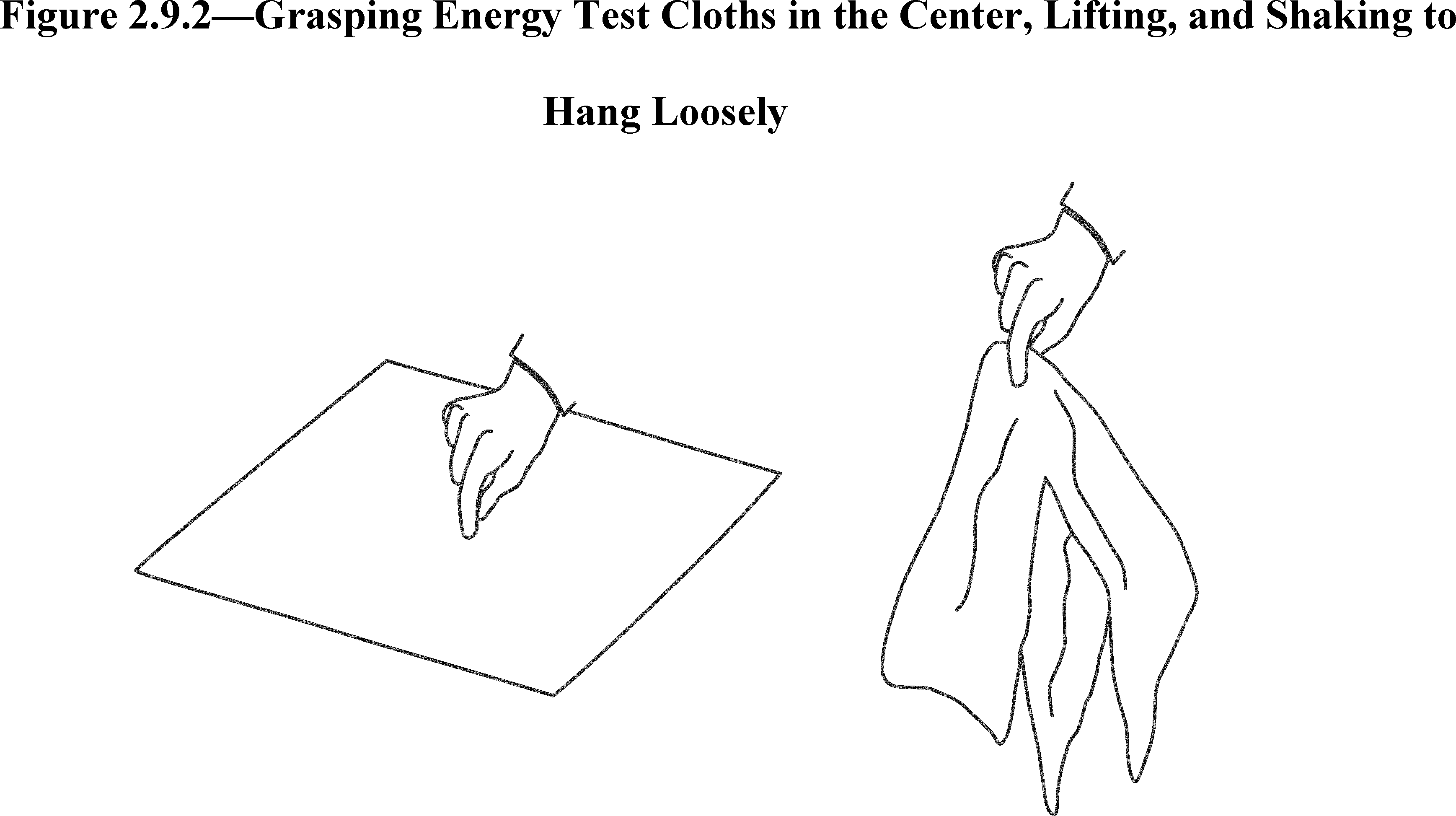
For all clothes washers, follow any manufacturer loading instructions provided to the user regarding the placement of clothing within the clothes container. In the absence of any manufacturer instructions regarding the placement of clothing within the clothes container, the following loading instructions apply.
2.9.2.1 To load the energy test cloths in a top-loading clothes washer, arrange the cloths circumferentially around the axis of rotation of the clothes container, using alternating lengthwise orientations for adjacent pieces of cloth. Complete each cloth layer across its horizontal plane within the clothes container before adding a new layer. Figure 2.9.2.1 of this appendix illustrates the correct loading technique for a vertical-axis clothes washer.

2.9.2.2 To load the energy test cloths in a front-loading clothes washer, grasp each test cloth in the center as indicted in section 2.9.2 of this appendix, and then place each cloth into the clothes container prior to activating the clothes washer.
2.10 Clothes washer installation. Install the clothes washer in accordance with manufacturer's instructions. For combined low-power mode testing, install the clothes washer in accordance with Section 5, Paragraph 5.2 of IEC 62301 (incorporated by reference; see § 430.3), disregarding the provisions regarding batteries and the determination, classification, and testing of relevant modes.
2.11 Clothes washer pre-conditioning.
2.11.1 Non-water-heating clothes washer. If the clothes washer has not been filled with water in the preceding 96 hours, pre-condition it by running it through a cold rinse cycle and then draining it to ensure that the hose, pump, and sump are filled with water.
2.11.2 Water-heating clothes washer. If the clothes washer has not been filled with water in the preceding 96 hours, or if it has not been in the test room at the specified ambient conditions for 8 hours, pre-condition it by running it through a cold rinse cycle and then draining it to ensure that the hose, pump, and sump are filled with water.
2.12 Determining the energy test cycle. To determine the energy test cycle, evaluate the wash/rinse temperature selection flowcharts in the order in which they are presented in this section. The determination of the energy test cycle must take into consideration all cycle settings available to the end user, including any cycle selections or cycle modifications provided by the manufacturer via software or firmware updates to the product, for the basic model under test. The energy test cycle does not include any cycle that is recommended by the manufacturer exclusively for cleaning, deodorizing, or sanitizing the clothes washer.
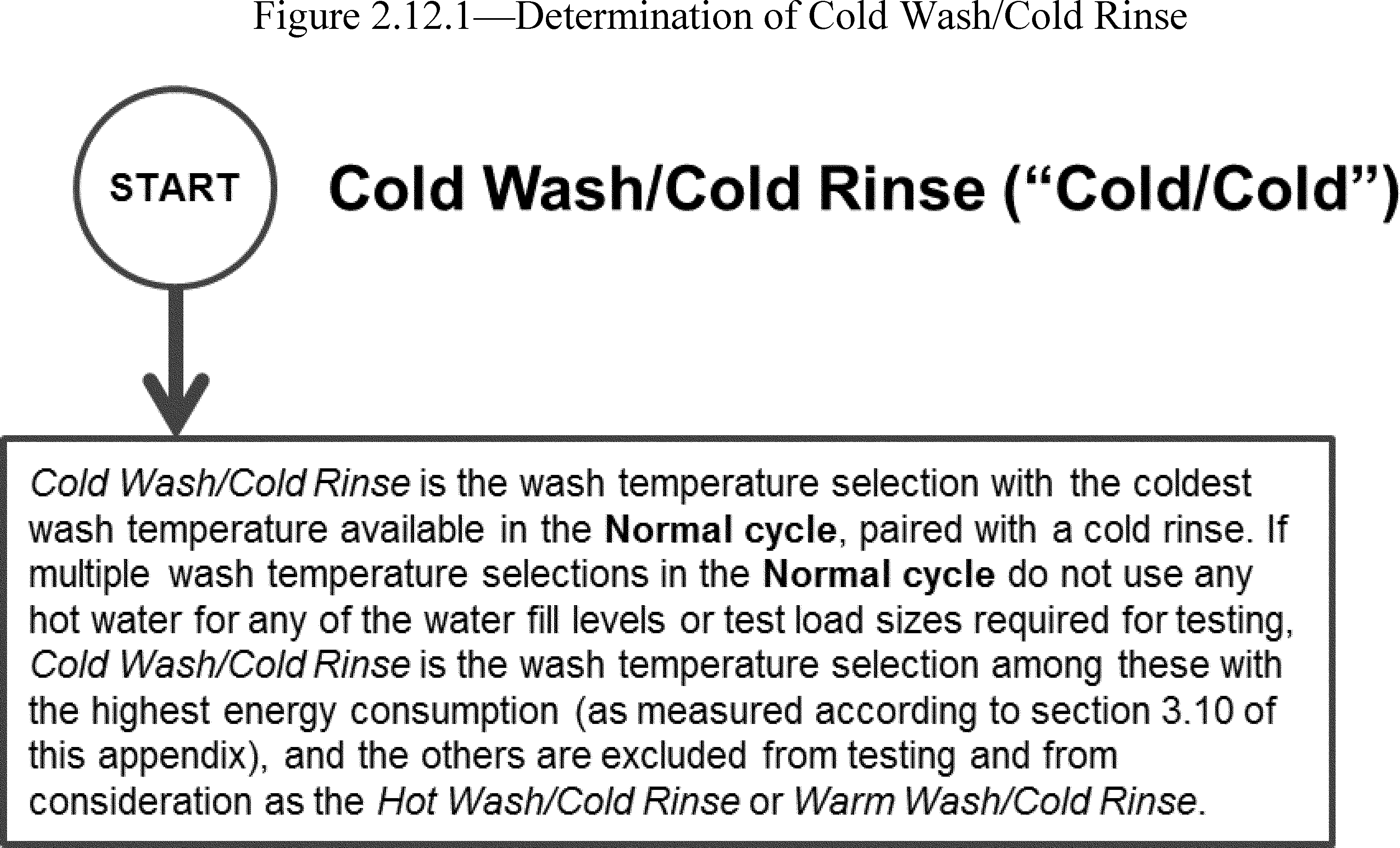

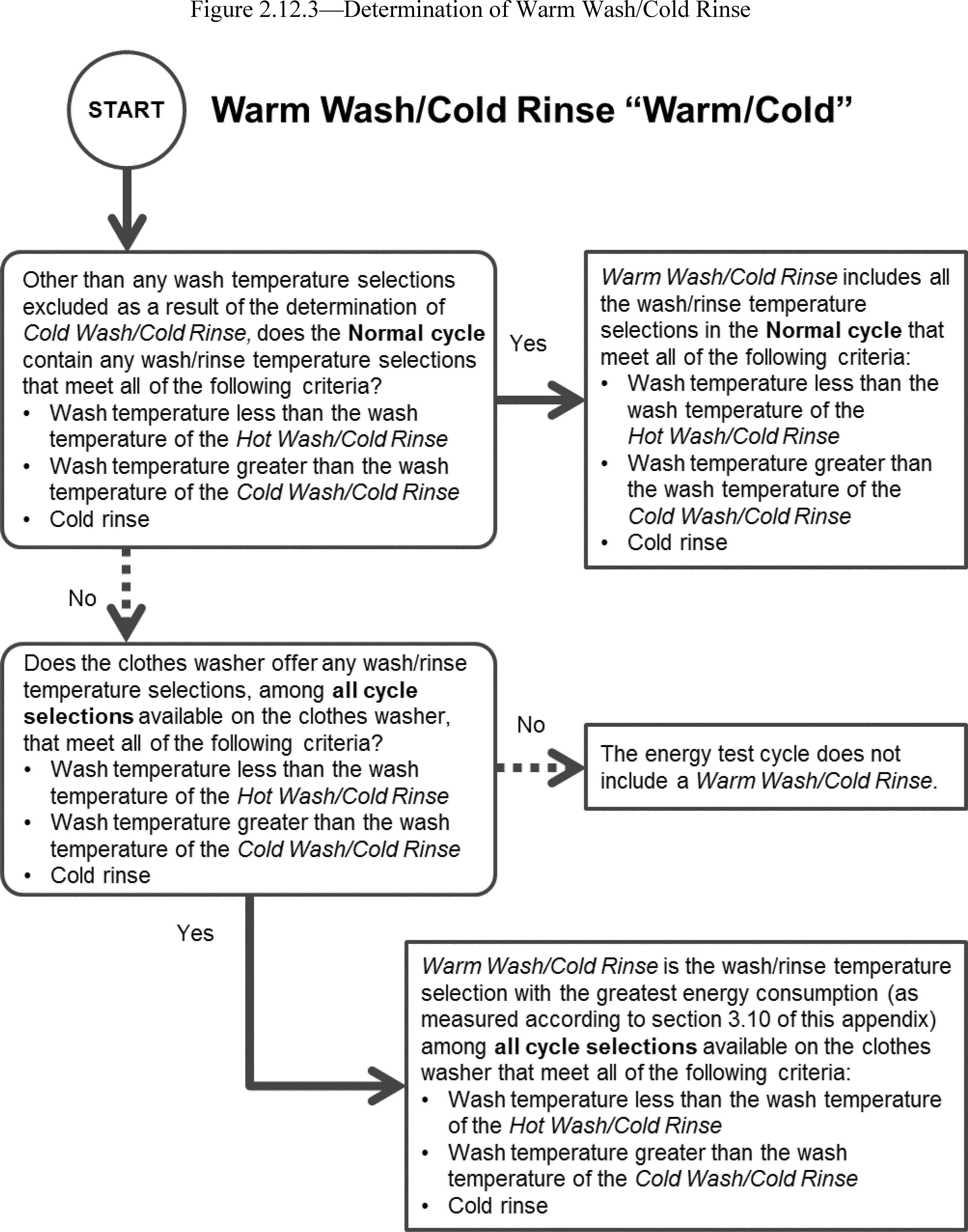
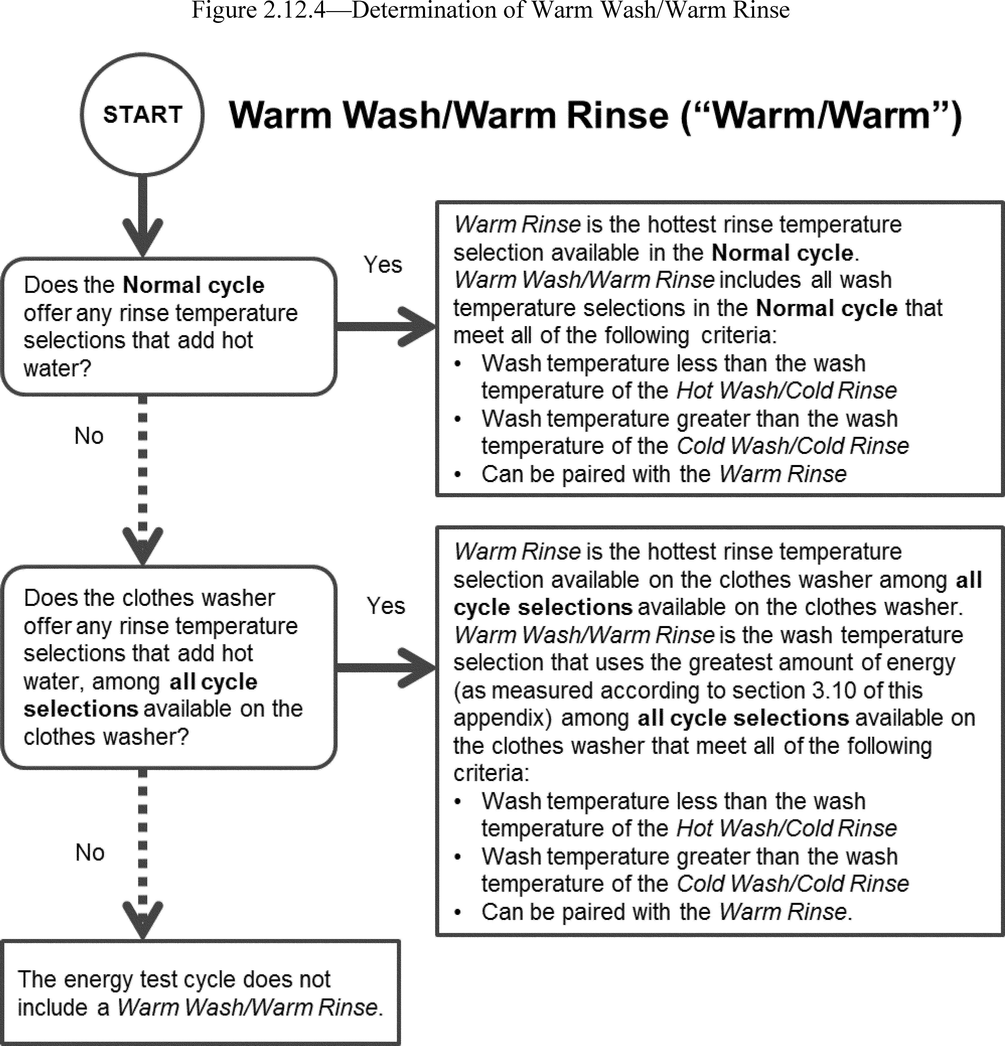

3. Test Measurements
3.1 Clothes container capacity. Measure the entire volume that a clothes load could occupy within the clothes container during active mode washer operation according to the following procedures:
3.1.1 Place the clothes washer in such a position that the uppermost edge of the clothes container opening is leveled horizontally, so that the container will hold the maximum amount of water. For front-loading clothes washers, the door seal and shipping bolts or other forms of bracing hardware to support the wash drum during shipping must remain in place during the capacity measurement.
If the design of a front-loading clothes washer does not include shipping bolts or other forms of bracing hardware to support the wash drum during shipping, a laboratory may support the wash drum by other means, including temporary bracing or support beams. Any temporary bracing or support beams must keep the wash drum in a fixed position, relative to the geometry of the door and door seal components, that is representative of the position of the wash drum during normal operation. The method used must avoid damage to the unit that would affect the results of the energy and water testing.
For a front-loading clothes washer that does not include shipping bolts or other forms of bracing hardware to support the wash drum during shipping, the laboratory must fully document the alternative method used to support the wash drum during capacity measurement, include such documentation in the final test report, and pursuant to § 429.71 of this chapter, the manufacturer must retain such documentation as part its test records.
3.1.2 Line the inside of the clothes container with a 2 mil thickness (0.051 mm) plastic bag. All clothes washer components that occupy space within the clothes container and that are recommended for use during a wash cycle must be in place and must be lined with a 2 mil thickness (0.051 mm) plastic bag to prevent water from entering any void space.
3.1.3 Record the total weight of the machine before adding water.
3.1.4 Fill the clothes container manually with either 60 °F ± 5 °F (15.6 °C ± 2.8 °C) or 100 °F ± 10 °F (37.8 °C ± 5.5 °C) water, with the door open. For a top-loading vertical-axis clothes washer, fill the clothes container to the uppermost edge of the rotating portion, including any balance ring. Figure 3.1.4.1 of this appendix illustrates the maximum fill level for top-loading clothes washers.

For a front-loading horizontal-axis clothes washer, fill the clothes container to the highest point of contact between the door and the door gasket. If any portion of the door or gasket would occupy the measured volume space when the door is closed, exclude from the measurement the volume that the door or gasket portion would occupy. For a front-loading horizontal-axis clothes washer with a concave door shape, include any additional volume above the plane defined by the highest point of contact between the door and the door gasket, if that area can be occupied by clothing during washer operation. For a top-loading horizontal-axis clothes washer, include any additional volume above the plane of the door hinge that clothing could occupy during washer operation. Figure 3.1.4.2 of this appendix illustrates the maximum fill volumes for all horizontal-axis clothes washer types.

For all clothes washers, exclude any volume that cannot be occupied by the clothing load during operation.
3.1.5 Measure and record the weight of water, W, in pounds.
3.1.6 Calculate the clothes container capacity as follows:
C = W/d
where:
C = Capacity in cubic feet (liters).
W = Mass of water in pounds (kilograms).
d = Density of water (62.0 lbs/ft3 for 100 °F (993 kg/m3 for 37.8 °C) or 62.3 lbs/ft3 for 60 °F (998 kg/m3 for 15.6 °C)).
3.1.7 Calculate the clothes container capacity, C, to the nearest 0.01 cubic foot for the purpose of determining test load sizes per Table 5.1 of this appendix and for all subsequent calculations that include the clothes container capacity.
3.2 Procedure for measuring water and energy consumption values on all automatic and semi-automatic washers.
3.2.1 Perform all energy consumption tests under the energy test cycle.
3.2.2 Perform the test sections listed in Table 3.2.2 in accordance with the wash/rinse temperature selections available in the energy test cycle.
Table 3.2.2 - Test Section Reference
| Wash/rinse temperature
selections available in the energy test cycle |
Corresponding test section
reference |
|---|---|
| Extra-Hot/Cold | 3.3 |
| Hot/Cold | 3.4 |
| Warm/Cold | 3.5 |
| Warm/Warm | 3.6 |
| Cold/Cold | 3.7 |
| Test Sections Applicable to all Clothes Washers | |
| Remaining Moisture Content | 3.8 |
| Combined Low-Power Mode Power | 3.9 |
3.2.3 Hot and cold water faucets.
3.2.3.1 For automatic clothes washers, open both the hot and cold water faucets.
3.2.3.2 For semi-automatic washers:
(1) For hot inlet water temperature, open the hot water faucet completely and close the cold water faucet;
(2) For warm inlet water temperature, open both hot and cold water faucets completely;
(3) For cold inlet water temperature, close the hot water faucet and open the cold water faucet completely.
3.2.4 Wash/rinse temperature selection. Set the wash/rinse temperature selection control to obtain the desired wash/rinse temperature selection within the energy test cycle.
3.2.5 Wash time setting. If one wash time is prescribed for the wash cycle under test, that shall be the wash time setting; otherwise, the wash time setting shall be the higher of either the minimum or 70 percent of the maximum wash time available for the wash cycle under test, regardless of the labeling of suggested dial locations. If 70% of the maximum wash time is not available on a dial with a discreet number of wash time settings, choose the next-highest setting greater than 70%. If the clothes washer is equipped with an electromechanical dial controlling wash time, reset the dial to the minimum wash time and then turn it in the direction of increasing wash time to reach the appropriate setting. If the appropriate setting is passed, return the dial to the minimum wash time and then turn in the direction of increasing wash time until the appropriate setting is reached.
3.2.6 Water fill levels.
3.2.6.1 Clothes washers with manual water fill control system. Set the water fill selector to the maximum water level available for the wash cycle under test for the maximum test load size and the minimum water level available for the wash cycle under test for the minimum test load size.
3.2.6.2 Clothes washers with automatic water fill control system.
3.2.6.2.1 Not user adjustable. The maximum, minimum, and average water levels as described in the following sections refer to the amount of water fill that is automatically selected by the control system when the respective test loads are used.
3.2.6.2.2 User adjustable. Conduct four tests on clothes washers with user adjustable automatic water fill controls that affect the relative wash water levels. Conduct the first test using the maximum test load and with the automatic water fill control system set in the setting that will give the most energy intensive result. Conduct the second test using the minimum test load and with the automatic water fill control system set in the setting that will give the least energy intensive result. Conduct the third test using the average test load and with the automatic water fill control system set in the setting that will give the most energy intensive result for the given test load. Conduct the fourth test using the average test load and with the automatic water fill control system set in the setting that will give the least energy intensive result for the given test load. Average the results of the third and fourth tests to obtain the energy and water consumption values for the average test load size.
3.2.6.3 Clothes washers with automatic water fill control system and alternate manual water fill control system. If a clothes washer with an automatic water fill control system allows user selection of manual controls as an alternative, test both manual and automatic modes and, for each mode, calculate the energy consumption (HET, MET, and DE) and water consumption (QT) values as set forth in section 4 of this appendix. Then, calculate the average of the two values (one from each mode, automatic and manual) for each variable (HET, MET, DE, and QT) and use the average value for each variable in the final calculations in section 4 of this appendix.
3.2.7 Manufacturer default settings. For clothes washers with electronic control systems, use the manufacturer default settings for any cycle selections, except for
(1) the temperature selection,
(2) the wash water fill levels, or
(3) if necessary, the spin speeds on wash cycles used to determine remaining moisture content. Specifically, the manufacturer default settings must be used for wash conditions such as agitation/tumble operation, soil level, spin speed on wash cycles used to determine energy and water consumption, wash times, rinse times, optional rinse settings, water heating time for water heating clothes washers, and all other wash parameters or optional features applicable to that wash cycle. Any optional wash cycle feature or setting (other than wash/rinse temperature, water fill level selection, or spin speed on wash cycles used to determine remaining moisture content) that is activated by default on the wash cycle under test must be included for testing unless the manufacturer instructions recommend not selecting this option, or recommend selecting a different option, for washing normally soiled cotton clothing.
For clothes washers with control panels containing mechanical switches or dials, any optional settings, except for (1) the temperature selection, (2) the wash water fill levels, or (3) if necessary, the spin speeds on wash cycles used to determine remaining moisture content, must be in the position recommended by the manufacturer for washing normally soiled cotton clothing. If the manufacturer instructions do not recommend a particular switch or dial position to be used for washing normally soiled cotton clothing, the setting switch or dial must remain in its as-shipped position.
3.2.8 For each wash cycle tested, include the entire active washing mode and exclude any delay start or cycle finished modes.
3.2.9 Discard the data from a wash cycle that provides a visual or audio indicator to alert the user that an out-of-balance condition has been detected, or that terminates prematurely if an out-of-balance condition is detected, and thus does not include the agitation/tumble operation, spin speed(s), wash times, and rinse times applicable to the wash cycle under test. Document in the test report the rejection of data from any wash cycle during testing and the reason for the rejection.
3.3 Extra-Hot Wash/Cold Rinse. Measure the water and electrical energy consumption for each water fill level and test load size as specified in sections 3.3.1 through 3.3.3 of this appendix for the Extra-Hot Wash/Cold Rinse as defined within the energy test cycle.
Non-reversible temperature indicator labels, adhered to the inside of the clothes container, may be used to confirm that an extra-hot wash temperature greater than 135 °F has been achieved during the wash cycle, under the following conditions. The label must remain waterproof, intact, and adhered to the wash drum throughout an entire wash cycle; provide consistent maximum temperature readings; and provide repeatable temperature indications sufficient to demonstrate that a wash temperature of greater than 135 °F has been achieved. The label must have been verified to consistently indicate temperature measurements with an accuracy of ±1 °F if the label provides a temperature indicator at 135 °F. If the label does not provide a temperature indicator at 135 °F, the label must have been verified to consistently indicate temperature measurements with an accuracy of ±1 °F if the next-highest temperature indicator is greater than 135 °F and less than 140 °F, or ±3 °F if the next-highest temperature indicator is 140 °F or greater. If the label does not provide a temperature indicator at 135 °F, failure to activate the next-highest temperature indicator does not necessarily indicate the lack of an extra-hot wash temperature. However, such a result would not be considered a valid test due to the lack of verification of the water temperature requirement, in which case an alternative method must be used to confirm that an extra-hot wash temperature greater than 135 °F has been achieved during the wash cycle.
If using a temperature indicator label to test a front-loading clothes washer, adhere the label along the interior surface of the clothes container drum, midway between the front and the back of the drum, adjacent to one of the baffles. If using a temperature indicator label to test a top-loading clothes washer, adhere the label along the interior surface of the clothes container drum, on the vertical portion of the sidewall, as close to the bottom of the container as possible.
3.3.1 Maximum test load and water fill. Measure the values for hot water consumption (HmX), cold water consumption (CmX), and electrical energy consumption (EmX) for an Extra-Hot Wash/Cold Rinse cycle, with the controls set for the maximum water fill level. Use the maximum test load size as specified in Table 5.1 of this appendix.
3.3.2 Minimum test load and water fill. Measure the values for hot water consumption (Hmn), cold water consumption (Cmn), and electrical energy consumption (Emn) for an Extra-Hot Wash/Cold Rinse cycle, with the controls set for the minimum water fill level. Use the minimum test load size as specified in Table 5.1 of this appendix.
3.3.3 Average test load and water fill. For a clothes washer with an automatic water fill control system, measure the values for hot water consumption (Hma), cold water consumption (Cma), and electrical energy consumption (Ema) for an Extra-Hot Wash/Cold Rinse cycle. Use the average test load size as specified in Table 5.1 of this appendix.
3.4 Hot Wash/Cold Rinse. Measure the water and electrical energy consumption for each water fill level and test load size as specified in sections 3.4.1 through 3.4.3 of this appendix for the Hot Wash/Cold Rinse temperature selection, as defined within the energy test cycle.
3.4.1 Maximum test load and water fill. Measure the values for hot water consumption (HhX), cold water consumption (ChX), and electrical energy consumption (EhX) for a Hot Wash/Cold Rinse cycle, with the controls set for the maximum water fill level. Use the maximum test load size as specified in Table 5.1 of this appendix.
3.4.2 Minimum test load and water fill. Measure the values for hot water consumption (Hhn), cold water consumption (Chn), and electrical energy consumption (Ehn) for a Hot Wash/Cold Rinse cycle, with the controls set for the minimum water fill level. Use the minimum test load size as specified in Table 5.1 of this appendix.
3.4.3 Average test load and water fill. For a clothes washer with an automatic water fill control system, measure the values for hot water consumption (Hha), cold water consumption (Cha), and electrical energy consumption (Eha) for a Hot Wash/Cold Rinse cycle. Use the average test load size as specified in Table 5.1 of this appendix.
3.5 Warm Wash/Cold Rinse. Measure the water and electrical energy consumption for each water fill level and test load size as specified in sections 3.5.1 through 3.5.3 of this appendix for the applicable Warm Wash/Cold Rinse temperature selection(s), as defined within the energy test cycle.
For a clothes washer with fewer than four discrete Warm Wash/Cold Rinse temperature selections, test all Warm Wash/Cold Rinse selections. For a clothes washer that offers four or more Warm Wash/Cold Rinse selections, test at all discrete selections, or test at the 25 percent, 50 percent, and 75 percent positions of the temperature selection device between the hottest hot (≤135 °F (57.2 °C)) wash and the coldest cold wash. If a selection is not available at the 25, 50 or 75 percent position, in place of each such unavailable selection, use the next warmer setting. For each reportable value to be used for the Warm Wash/Cold Rinse temperature selection, calculate the average of all Warm Wash/Cold Rinse temperature selections tested pursuant to this section.
3.5.1 Maximum test load and water fill. Measure the values for hot water consumption (HwX), cold water consumption (CwX), and electrical energy consumption (EwX) for the Warm Wash/Cold Rinse cycle, with the controls set for the maximum water fill level. Use the maximum test load size as specified in Table 5.1 of this appendix.
3.5.2 Minimum test load and water fill. Measure the values for hot water consumption (Hwn), cold water consumption (Cwn), and electrical energy consumption (Ewn) for the Warm Wash/Cold Rinse cycle, with the controls set for the minimum water fill level. Use the minimum test load size as specified in Table 5.1 of this appendix.
3.5.3 Average test load and water fill. For a clothes washer with an automatic water fill control system, measure the values for hot water consumption (Hwa), cold water consumption (Cwa), and electrical energy consumption (Ewa) for a Warm Wash/Cold Rinse cycle. Use the average test load size as specified in Table 5.1 of this appendix.
3.6 Warm Wash/Warm Rinse. Measure the water and electrical energy consumption for each water fill level and/or test load size as specified in sections 3.6.1 through 3.6.3 of this appendix for the applicable Warm Wash/Warm Rinse temperature selection(s), as defined within the energy testy cycle.
For a clothes washer with fewer than four discrete Warm Wash/Warm Rinse temperature selections, test all Warm Wash/Warm Rinse selections. For a clothes washer that offers four or more Warm Wash/Warm Rinse selections, test at all discrete selections, or test at 25 percent, 50 percent, and 75 percent positions of the temperature selection device between the hottest hot (≤135 °F (57.2 °C)) wash and the coldest cold wash. If a selection is not available at the 25, 50 or 75 percent position, in place of each such unavailable selection use the next warmer setting. For each reportable value to be used for the Warm Wash/Warm Rinse temperature selection, calculate the arithmetic average of all Warm Wash/Warm Rinse temperature selections tested pursuant to this section.
3.6.1 Maximum test load and water fill. Measure the values for hot water consumption (HwwX), cold water consumption (CwwX), and electrical energy consumption (EwwX) for the Warm Wash/Warm Rinse cycle, with the controls set for the maximum water fill level. Use the maximum test load size as specified in Table 5.1 of this appendix.
3.6.2 Minimum test load and water fill. Measure the values for hot water consumption (Hwwn), cold water consumption (Cwwn), and electrical energy consumption (Ewwn) for the Warm Wash/Warm Rinse cycle, with the controls set for the minimum water fill level. Use the minimum test load size as specified in Table 5.1 of this appendix.
3.6.3 Average test load and water fill. For a clothes washer with an automatic water fill control system, measure the values for hot water consumption (Hwwa), cold water consumption (Cwwa), and electrical energy consumption (Ewwa) for the Warm Wash/Warm Rinse cycle. Use the average test load size as specified in Table 5.1 of this appendix.
3.7 Cold Wash/Cold Rinse. Measure the water and electrical energy consumption for each water fill level and test load size as specified in sections 3.7.1 through 3.7.3 of this appendix for the applicable Cold Wash/Cold Rinse temperature selection, as defined within the energy test cycle.
3.7.1 Maximum test load and water fill. Measure the values for hot water consumption (HcX), cold water consumption (CcX), and electrical energy consumption (EcX) for a Cold Wash/Cold Rinse cycle, with the controls set for the maximum water fill level. Use the maximum test load size as specified in Table 5.1 of this appendix.
3.7.2 Minimum test load and water fill. Measure the values for hot water consumption (Hcn), cold water consumption (Ccn), and electrical energy consumption (Ecn) for a Cold Wash/Cold Rinse cycle, with the controls set for the minimum water fill level. Use the minimum test load size as specified in Table 5.1 of this appendix.
3.7.3 Average test load and water fill. For a clothes washer with an automatic water fill control system, measure the values for hot water consumption (Hca), cold water consumption (Cca), and electrical energy consumption (Eca) for a Cold Wash/Cold Rinse cycle. Use the average test load size as specified in Table 5.1 of this appendix.
3.8 Remaining moisture content (RMC).
3.8.1 The wash temperature must be the same as the rinse temperature for all testing. Use the maximum test load as defined in Table 5.1 of this appendix for testing.
3.8.2 Clothes washers with cold rinse only.
3.8.2.1 Record the actual “bone dry” weight of the test load (WIX), then place the test load in the clothes washer.
3.8.2.2 Set the water level controls to maximum fill.
3.8.2.3 Run the Cold Wash/Cold Rinse cycle.
3.8.2.4 Record the weight of the test load immediately after completion of the wash cycle (WCX).
3.8.2.5 Calculate the remaining moisture content of the maximum test load, RMCX, defined as:
RMCX = (WCX − WIX)/WIX
3.8.2.6 Apply the RMC correction curve described in section 7 of appendix J3 to this subpart to calculate the corrected remaining moisture content, RMCcorr, expressed as a percentage as follows:
RMCcorr = (A × RMCX + B) × 100%
where:
A and B are the coefficients of the RMC correction curve as defined in section 6.1 of appendix J3 to this subpart.
RMCX = As defined in section 3.8.2.5 of this appendix.
3.8.2.7 Use RMCcorr as the final corrected RMC in section 4.3 of this appendix.
3.8.3 Clothes washers with both cold and warm rinse options.
3.8.3.1 Complete sections 3.8.2.1 through 3.8.2.4 of this appendix for a Cold Wash/Cold Rinse cycle. Calculate the remaining moisture content of the maximum test load for Cold Wash/Cold Rinse, RMCCOLD, defined as:
RMCCOLD = (WCX − WIX)/WIX
3.8.3.2 Apply the RMC correction curve described in section 7 of appendix J3 to this subpart to calculate the corrected remaining moisture content for Cold Wash/Cold Rinse, RMCCOLD,corr, expressed as a percentage, as follows:
RMCCOLD,corr = (A × RMCCOLD + B) × 100%
where:
A and B are the coefficients of the RMC correction curve as defined in section 6.1 of appendix J3 to this subpart.
RMCCOLD = As defined in section 3.8.3.1 of this appendix.
3.8.3.3 Complete sections 3.8.2.1 through 3.8.2.4 of this appendix using a Warm Wash/Warm Rinse cycle instead. Calculate the remaining moisture content of the maximum test load for Warm Wash/Warm Rinse, RMCWARM, defined as:
RMCWARM = (WCX−WIX)/WIX
3.8.3.4 Apply the RMC correction curve described in section 7 of appendix J3 to this subpart to calculate the corrected remaining moisture content for Warm Wash/Warm Rinse, RMCWARM,corr, expressed as a percentage, as follows:
RMCWARM,corr = (A × RMCWARM + B) × 100%
where:
A and B are the coefficients of the RMC correction curve as defined in section 6.1 of appendix J3 to this subpart.
RMCWARM = As defined in section 3.8.3.3 of this appendix.
3.8.3.5 Calculate the corrected remaining moisture content of the maximum test load, RMCcorr, expressed as a percentage as follows:
RMCcorr = RMCCOLD,corr × (1 − TUFww) + RMCWARM,corr × (TUFww)
where:
RMCCOLD,corr = As defined in section 3.8.3.2 of this Appendix.
RMCWARM,corr = As defined in section 3.8.3.4 of this Appendix.
TUFww is the temperature use factor for Warm Wash/Warm Rinse as defined in Table 4.1.1 of this appendix.
3.8.3.6 Use RMCcorr as calculated in section 3.8.3.5 as the final corrected RMC used in section 4.3 of this appendix.
3.8.4 Clothes washers that have options such as multiple selections of spin speeds or spin times that result in different RMC values, and that are available within the energy test cycle.
3.8.4.1 Complete sections 3.8.2 or 3.8.3 of this appendix, as applicable, using the maximum and minimum extremes of the available spin options, excluding any “no spin” (zero spin speed) settings. Combine the calculated values RMCcorr,max extraction and RMCcorr,min extraction at the maximum and minimum settings, respectively, as follows:
RMCcorr = 0.75 × RMCcorr,max extraction + 0.25 × RMCcorr,min extraction
where:
RMCcorr, max extraction is the corrected remaining moisture content using the maximum spin setting, calculated according to section 3.8.2 or 3.8.3 of this appendix, as applicable.
RMCcorr, min extraction is the corrected remaining moisture content using the minimum spin setting, calculated according to section 3.8.2 or 3.8.3 of this appendix, as applicable.
3.8.4.2 Use RMCcorr as calculated in section 3.8.4.1 as the final corrected RMC used in section 4.3 of this appendix.
3.8.5 The procedure for calculating the corrected RMC as described in section 3.8.2, 3.8.3, or 3.8.4 of this appendix may be replicated twice in its entirety, for a total of three independent corrected RMC measurements. If three replications of the RMC measurement are performed, use the average of the three corrected RMC measurements as the final corrected RMC in section 4.3 of this appendix.
3.9 Combined low-power mode power. Connect the clothes washer to a watt meter as specified in section 2.5.3 of this appendix. Establish the testing conditions set forth in sections 2.1, 2.4, and 2.10 of this appendix.
3.9.1 Perform combined low-power mode testing after completion of an active mode wash cycle included as part of the energy test cycle; after removing the test load; without changing the control panel settings used for the active mode wash cycle; with the door closed; and without disconnecting the electrical energy supply to the clothes washer between completion of the active mode wash cycle and the start of combined low-power mode testing.
3.9.2 For a clothes washer that takes some time to automatically enter a stable inactive mode or off mode state from a higher power state as discussed in Section 5, Paragraph 5.1, note 1 of IEC 62301 (incorporated by reference; see § 430.3), allow sufficient time for the clothes washer to automatically reach the default inactive/off mode state before proceeding with the test measurement.
3.9.3 Once the stable inactive/off mode state has been reached, measure and record the default inactive/off mode power, Pdefault, in watts, following the test procedure for the sampling method specified in Section 5, Paragraph 5.3.2 of IEC 62301.
3.9.4 For a clothes washer with a switch, dial, or button that can be optionally selected by the end user to achieve a lower-power inactive/off mode state than the default inactive/off mode state measured in section 3.9.3 of this appendix, after performing the measurement in section 3.9.3, activate the switch, dial, or button to the position resulting in the lowest power consumption and repeat the measurement procedure described in section 3.9.3. Measure and record the lowest-power inactive/off mode power, Plowest, in Watts.
3.10 Energy consumption for the purpose of determining the cycle selection(s) to be included in the energy test cycle. This section is implemented only in cases where the energy test cycle flowcharts in section 2.12 require the determination of the wash/rinse temperature selection with the highest energy consumption.
3.10.1 For the wash/rinse temperature selection being considered under this section, establish the testing conditions set forth in section 2 of this appendix. Select the applicable cycle selection and wash/rinse temperature selection. For all wash/rinse temperature selections, the manufacturer default settings shall be used as described in section 3.2.7 of this appendix.
3.10.2 Use the clothes washer's maximum test load size, determined from Table 5.1 of this appendix, for testing under this section.
3.10.3 For clothes washers with a manual fill control system, user-adjustable automatic water fill control system, or automatic water fill control system with alternate manual water fill control system, use the water fill selector setting resulting in the maximum water level available for each cycle selection for testing under this section.
3.10.4 Each wash cycle tested under this section shall include the entire active washing mode and exclude any delay start or cycle finished modes.
3.10.5 Measure each wash cycle's electrical energy consumption (EX) and hot water consumption (HX). Calculate the total energy consumption for each cycle selection (ETX), as follows:
ETX = EX + (HX × T × K)
where:
EX is the electrical energy consumption, expressed in kilowatt-hours per cycle.
HX is the hot water consumption, expressed in gallons per cycle.
T = nominal temperature rise = 75 °F (41.7 °C).
K = Water specific heat in kilowatt-hours per gallon per degree F = 0.00240 kWh/gal - °F (0.00114 kWh/L- °C).
4. Calculation of Derived Results From Test Measurements
4.1 Hot water and machine electrical energy consumption of clothes washers.
4.1.1 Per-cycle temperature-weighted hot water consumption for all maximum, average, and minimum water fill levels tested. Calculate the per-cycle temperature-weighted hot water consumption for the maximum water fill level, VhX, the average water fill level, Vha, and the minimum water fill level, Vhn, expressed in gallons per cycle (or liters per cycle) and defined as:
(a) VhX = [HmX × TUFm] + [HhX × TUFh] + [HwX × TUFw] + [HwwX × TUFww] + [HcX × TUFc]
(b) Vha = [Hma × TUFm] + [Hha × TUFh] + [Hwa × TUFw] + [Hwwa × TUFww] + [Hca × TUFc]
(c) Vhn = [Hmn × TUFm] + [Hhn × TUFh] + [Hwn × TUFw] + [Hwwn × TUFww] + [Hcn × TUFc]
where:
HmX, Hma, and Hmn, are reported hot water consumption values, in gallons per-cycle (or liters per cycle), at maximum, average, and minimum water fill levels, respectively, for the Extra-Hot Wash/Cold Rinse cycle, as measured in sections 3.3.1 through 3.3.3 of this appendix.
HhX, Hha, and Hhn, are reported hot water consumption values, in gallons per-cycle (or liters per cycle), at maximum, average, and minimum water fill levels, respectively, for the Hot Wash/Cold Rinse cycle, as measured in sections 3.4.1 through 3.4.3 of this appendix.
HwX, Hwa, and Hwn, are reported hot water consumption values, in gallons per-cycle (or liters per cycle), at maximum, average, and minimum water fill levels, respectively, for the Warm Wash/Cold Rinse cycle, as measured in sections 3.5.1 through 3.5.3 of this appendix.
HwwX, Hwwa, and Hwwn, are reported hot water consumption values, in gallons per-cycle (or liters per cycle), at maximum, average, and minimum water fill levels, respectively, for the Warm Wash/Warm Rinse cycle, as measured in sections 3.6.1 through 3.6.3 of this appendix.
HcX, Hca, and Hcn, are reported hot water consumption values, in gallons per-cycle (or liters per cycle), at maximum, average, and minimum water fill levels, respectively, for the Cold Wash/Cold Rinse cycle, as measured in sections 3.7.1 through 3.7.3 of this appendix.
TUFm, TUFh, TUFw, TUFww, and TUFc are temperature use factors for Extra-Hot Wash/Cold Rinse, Hot Wash/Cold Rinse, Warm Wash/Cold Rinse, Warm Wash/Warm Rinse, and Cold Wash/Cold Rinse temperature selections, respectively, as defined in Table 4.1.1 of this appendix.
Table 4.1.1 - Temperature Use Factors
| Wash/Rinse Temperature Selections Available in the Energy Test Cycle | Clothes washers with cold rinse only | Clothes washers with both cold and warm rinse | ||||||
|---|---|---|---|---|---|---|---|---|
| C/C | H/C
C/C |
H/C
W/C C/C |
XH/C
H/C C/C |
XH/C
H/C W/C C/C |
H/C
W/C W/W C/C |
XH/C
H/C W/W C/C |
XH/C
H/C W/C W/W C/C |
|
| TUFm (Extra-Hot/Cold) | 0.14 | 0.05 | 0.14 | 0.05 | ||||
| TUFh (Hot/Cold) | 0.63 | 0.14 | * 0.49 | 0.09 | 0.14 | * 0.22 | 0.09 | |
| TUFw (Warm/Cold) | 0.49 | 0.49 | 0.22 | 0.22 | ||||
| TUFww (Warm/Warm) | 0.27 | 0.27 | 0.27 | |||||
| TUFc (Cold/Cold) | 1.00 | 0.37 | 0.37 | 0.37 | 0.37 | 0.37 | 0.37 | 0.37 |
4.1.2 Total per-cycle hot water energy consumption for all maximum, average, and minimum water fill levels tested. Calculate the total per-cycle hot water energy consumption for the maximum water fill level, HEmax, the average water fill level, HEavg, and the minimum water fill level, HEmin, expressed in kilowatt-hours per cycle and defined as:
(a) HEmax = [VhX × T × K] = Total energy when a maximum load is tested.
(b) HEavg = [Vha × T × K] = Total energy when an average load is tested.
(c) HEmin = [Vhn × T × K] = Total energy when a minimum load is tested.
where:
VhX, Vha, and Vhn are defined in section 4.1.1 of this appendix.
T = Temperature rise = 75 °F (41.7 °C).
K = Water specific heat in kilowatt-hours per gallon per degree F = 0.00240 kWh/gal- °F (0.00114 kWh/L- °C).
4.1.3 Total weighted per-cycle hot water energy consumption. Calculate the total weighted per-cycle hot water energy consumption, HET, expressed in kilowatt-hours per cycle and defined as:
HET = [HEmax × Fmax] + [HEavg × Favg] + HEmin × Fmin]
where:
HEmax, HEavg, and HEmin are defined in section 4.1.2 of this appendix.
Fmax, Favg, and Fmin are the load usage factors for the maximum, average, and minimum test loads based on the size and type of the control system on the washer being tested, as defined in Table 4.1.3 of this appendix.
Table 4.1.3 - Load Usage Factors
| Load usage factor | Water fill control system | |
|---|---|---|
| Manual | Automatic | |
| Fmax = | 0.72 | 0.12 |
| Favg = | 0.74 | |
| Fmin = | 0.28 | 0.14 |
4.1.4 Total per-cycle hot water energy consumption using gas-heated or oil-heated water, for product labeling requirements. Calculate for the energy test cycle the per-cycle hot water consumption, HETG, using gas-heated or oil-heated water, expressed in Btu per cycle (or megajoules per cycle) and defined as:
HETG = HET × 1/e × 3412 Btu/kWh or HETG = HET × 1/e × 3.6 MJ/kWh
where:
e = Nominal gas or oil water heater efficiency = 0.75.
HET = As defined in section 4.1.3 of this Appendix.
4.1.5 Per-cycle machine electrical energy consumption for all maximum, average, and minimum test load sizes. Calculate the total per-cycle machine electrical energy consumption for the maximum water fill level, MEmax, the average water fill level, MEavg, and the minimum water fill level, MEmin, expressed in kilowatt-hours per cycle and defined as:
(a) MEmax = [EmX × TUFm] + [EhX × TUFh] + [EwX × TUFw] + [EwwX × TUFww] + [EcX × TUFc]
(b) MEavg = [Ema × TUFm] + [Eha × TUFh] + [Ewa × TUFw] + [Ewwa × TUFww] + [Eca × TUFc]
(c) MEmin = [Emn × TUFm] + [Ehn × TUFh] + [Ewn × TUFw] + [Ewwn × TUFww] + [Ecn × TUFc]
where:
EmX, Ema, and Emn, are reported electrical energy consumption values, in kilowatt-hours per cycle, at maximum, average, and minimum test loads, respectively, for the Extra-Hot Wash/Cold Rinse cycle, as measured in sections 3.3.1 through 3.3.3 of this appendix.
EhX, Eha, and Ehn, are reported electrical energy consumption values, in kilowatt-hours per cycle, at maximum, average, and minimum test loads, respectively, for the Hot Wash/Cold Rinse cycle, as measured in sections 3.4.1 through 3.4.3 of this appendix.
EwX, Ewa, and Ewn, are reported electrical energy consumption values, in kilowatt-hours per cycle, at maximum, average, and minimum test loads, respectively, for the Warm Wash/Cold Rinse cycle, as measured in sections 3.5.1 through 3.5.3 of this appendix.
EwwX, Ewwa, and Ewwn, are reported electrical energy consumption values, in kilowatt-hours per cycle, at maximum, average, and minimum test loads, respectively, for the Warm Wash/Warm Rinse cycle, as measured in sections 3.6.1 through 3.6.3 of this appendix.
EcX, Eca, and Ecn, are reported electrical energy consumption values, in kilowatt-hours per cycle, at maximum, average, and minimum test loads, respectively, for the Cold Wash/Cold Rinse cycle, as measured in sections 3.7.1 through 3.7.3 of this appendix.
TUFm, TUFh, TUFw, TUFww, and TUFc are defined in Table 4.1.1 of this appendix.
4.1.6 Total weighted per-cycle machine electrical energy consumption. Calculate the total weighted per-cycle machine electrical energy consumption, MET, expressed in kilowatt-hours per cycle and defined as:
MET = [MEmax × Fmax] + [MEavg × Favg] + [MEmin × Fmin]
where:
MEmax, MEavg, and MEmin are defined in section 4.1.5 of this appendix.
Fmax, Favg, and Fmin are defined in Table 4.1.3 of this appendix.
4.1.7 Total per-cycle energy consumption when electrically heated water is used. Calculate the total per-cycle energy consumption, ETE, using electrically heated water, expressed in kilowatt-hours per cycle and defined as:
ETE = HET + MET
where:
MET = As defined in section 4.1.6 of this appendix.
HET = As defined in section 4.1.3 of this appendix.
4.2 Water consumption of clothes washers.
4.2.1 Per-cycle water consumption for Extra-Hot Wash/Cold Rinse. Calculate the maximum, average, and minimum total water consumption, expressed in gallons per cycle (or liters per cycle), for the Extra-Hot Wash/Cold Rinse cycle and defined as:
Qmmax = [HmX + CmX]
Qmavg = [Hma + Cma]
Qmmin = [Hmn + Cmn]
where:
HmX, CmX, Hma, Cma, Hmn, and Cmn are defined in section 3.3 of this appendix.
4.2.2 Per-cycle water consumption for Hot Wash/Cold Rinse. Calculate the maximum, average, and minimum total water consumption, expressed in gallons per cycle (or liters per cycle), for the Hot Wash/Cold Rinse cycle and defined as:
Qhmax = [HhX + ChX]
Qhavg = [Hha + Cha]
Qhmin = [Hhn + Chn]
where:
HhX, ChX, Hha, Cha, Hhn, and Chn are defined in section 3.4 of this appendix.
4.2.3 Per-cycle water consumption for Warm Wash/Cold Rinse. Calculate the maximum, average, and minimum total water consumption, expressed in gallons per cycle (or liters per cycle), for the Warm Wash/Cold Rinse cycle and defined as:
Qwmax = [HwX + CwX]
Qwavg = [Hwa + Cwa]
Qwmin = [Hwn + Cwn]
where:
HwX, CwX, Hwa, Cwa, Hwn, and Cwn are defined in section 3.5 of this appendix.
4.2.4 Per-cycle water consumption for Warm Wash/Warm Rinse. Calculate the maximum, average, and minimum total water consumption, expressed in gallons per cycle (or liters per cycle), for the Warm Wash/Warm Rinse cycle and defined as:
Qwwmax = [HwwX + CwwX]
Qwwavg = [Hwwa + Cwwa]
Qwwmin = [Hwwn + Cwwn]
where:
HwwX, CwwX, Hwwa, Cwwa, Hwwn, and Cwwn are defined in section 3.6 of this appendix.
4.2.5 Per-cycle water consumption for Cold Wash/Cold Rinse. Calculate the maximum, average, and minimum total water consumption, expressed in gallons per cycle (or liters per cycle), for the Cold Wash/Cold Rinse cycle and defined as:
Qcmax = [HcX + CcX]
Qcavg = [Hca + Cca]
Qcmin = [Hcn + Ccn]
where:
HcX, CcX, Hca, Cca, Hcn, and Ccn are defined in section 3.7 of this appendix.
4.2.6 Total weighted per-cycle water consumption for Extra-Hot Wash/Cold Rinse. Calculate the total weighted per-cycle water consumption for the Extra-Hot Wash/Cold Rinse cycle, QmT, expressed in gallons per cycle (or liters per cycle) and defined as:
QmT = [Qmmax × Fmax] + [Qmavg × Favg] + [Qmmin × Fmin]
where:
Qmmax, Qmavg, Qmmin are defined in section 4.2.1 of this appendix.
Fmax, Favg, Fmin are defined in Table 4.1.3 of this appendix.
4.2.7 Total weighted per-cycle water consumption for Hot Wash/Cold Rinse. Calculate the total weighted per-cycle water consumption for the Hot Wash/Cold Rinse cycle, QhT, expressed in gallons per cycle (or liters per cycle) and defined as:
QhT = [Qhmax × Fmax] + [Qhavg × Favg] + [Qhmin × Fmin]
where:
Qhmax, Qhavg, Qhmin are defined in section 4.2.2 of this appendix.
Fmax, Favg, Fmin are defined in Table 4.1.3 of this appendix.
4.2.8 Total weighted per-cycle water consumption for Warm Wash/Cold Rinse. Calculate the total weighted per-cycle water consumption for the Warm Wash/Cold Rinse cycle, QwT, expressed in gallons per cycle (or liters per cycle) and defined as:
QwT = [Qwmax × Fmax] + [Qwavg × Favg] + [Qwmin × Fmin]
where:
Qwmax, Qwavg, Qwmin are defined in section 4.2.3 of this appendix.
Fmax, Favg, Fmin are defined in Table 4.1.3 of this appendix.
4.2.9 Total weighted per-cycle water consumption for Warm Wash/Warm Rinse. Calculate the total weighted per-cycle water consumption for the Warm Wash/Warm Rinse cycle, QwwT, expressed in gallons per cycle (or liters per cycle) and defined as:
QwwT = [Qwwmax × Fmax] + [Qwwavg × Favg] + [Qwwmin × Fmin]
where:
Qwwmax, Qwwavg, Qwwmin are defined in section 4.2.4 of this appendix.
Fmax, Favg, Fmin are defined in Table 4.1.3 of this appendix.
4.2.10 Total weighted per-cycle water consumption for Cold Wash/Cold Rinse. Calculate the total weighted per-cycle water consumption for the Cold Wash/Cold Rinse cycle, QcT, expressed in gallons per cycle (or liters per cycle) and defined as:
QcT = [Qcmax × Fmax] + [Qcavg × Favg] + [Qcmin × Fmin]
where:
Qcmax, Qcavg, Qcmin are defined in section 4.2.5 of this appendix.
Fmax, Favg, Fmin are defined in Table 4.1.3 of this appendix.
4.2.11 Total weighted per-cycle water consumption for all wash cycles. Calculate the total weighted per-cycle water consumption for all wash cycles, QT, expressed in gallons per cycle (or liters per cycle) and defined as:
QT = [QmT × TUFm] + [QhT × TUFh] + [QwT × TUFw] + [QwwT × TUFww] + [QcT × TUFc]
where:
QmT, QhT, QwT, QwwT, and QcT are defined in sections 4.2.6 through 4.2.10 of this appendix.
TUFm, TUFh, TUFw, TUFww, and TUFc are defined in Table 4.1.1 of this appendix.
4.2.12 Water factor. Calculate the water factor, WF, expressed in gallons per cycle per cubic foot (or liters per cycle per liter), as:
WF = QcT/C
where:
QcT = As defined in section 4.2.10 of this appendix.
C = As defined in section 3.1.7 of this appendix.
4.2.13 Integrated water factor. Calculate the integrated water factor, IWF, expressed in gallons per cycle per cubic foot (or liters per cycle per liter), as:
IWF = QT/C
where:
QT = As defined in section 4.2.11 of this appendix.
C = As defined in section 3.1.7 of this appendix.
4.3 Per-cycle energy consumption for removal of moisture from test load. Calculate the per-cycle energy required to remove the remaining moisture of the test load, DE, expressed in kilowatt-hours per cycle and defined as:
DE = [(Fmax × Maximum test load weight) + (Favg × Average test load weight) + (Fmin × Minimum test load weight)] × (RMCcorr - 4%) × (DEF) × (DUF)
where:
Fmax, Favg, and Fmin are defined in Table 4.1.3 of this appendix.
Maximum, average, and minimum test load weights are defined in Table 5.1 of this appendix.
RMCcorr = As defined in section 3.8.2.6, 3.8.3.5, or 3.8.4.1 of this Appendix.
DEF = Nominal energy required for a clothes dryer to remove moisture from clothes = 0.5 kWh/lb (1.1 kWh/kg).
DUF = Dryer usage factor, percentage of washer loads dried in a clothes dryer = 0.91.
4.4 Per-cycle combined low-power mode energy consumption. Calculate the per-cycle combined low-power mode energy consumption, ETLP, expressed in kilowatt-hours per cycle and defined as:
ETLP = [(Pdefault × Sdefault) + (Plowest × Slowest)] × Kp/295
where:
Pdefault = Default inactive/off mode power, in watts, as measured in section 3.9.3 of this appendix.
Plowest = Lowest-power inactive/off mode power, in watts, as measured in section 3.9.4 of this appendix for clothes washers with a switch, dial, or button that can be optionally selected by the end user to achieve a lower-power inactive/off mode than the default inactive/off mode; otherwise, Plowest=0.
Sdefault= Annual hours in default inactive/off mode, defined as 8,465 if no optional lowest-power inactive/off mode is available; otherwise 4,232.5.
Slowest= Annual hours in lowest-power inactive/off mode, defined as 0 if no optional lowest-power inactive/off mode is available; otherwise 4,232.5.
Kp = Conversion factor of watt-hours to kilowatt-hours = 0.001.
295 = Representative average number of clothes washer cycles in a year.
8,465 = Combined annual hours for inactive and off mode.
4,232.5 = One-half of the combined annual hours for inactive and off mode.
4.5 Modified energy factor. Calculate the modified energy factor, MEF, expressed in cubic feet per kilowatt-hour per cycle (or liters per kilowatt-hour per cycle) and defined as:
MEF = C/(ETE + DE)
where:
C = As defined in section 3.1.7 of this appendix.
ETE = As defined in section 4.1.7 of this appendix.
DE = As defined in section 4.3 of this appendix.
4.6 Integrated modified energy factor. Calculate the integrated modified energy factor, IMEF, expressed in cubic feet per kilowatt-hour per cycle (or liters per kilowatt-hour per cycle) and defined as:
IMEF = C/(ETE + DE + ETLP)
where:
C = As defined in section 3.1.7 of this appendix.
ETE = As defined in section 4.1.7 of this appendix.
DE = As defined in section 4.3 of this appendix.
ETLP = As defined in section 4.4 of this appendix.
5. Test Loads
Table 5.1 - Test Load Sizes
| Container volume | Minimum load | Maximum load | Average load | ||||
|---|---|---|---|---|---|---|---|
| cu. ft. | liter | lb | kg | lb | kg | lb | kg |
| ≥ < | ≥ < | ||||||
| 0.00-0.80 | 0.00-22.7 | 3.00 | 1.36 | 3.00 | 1.36 | 3.00 | 1.36 |
| 0.80-0.90 | 22.7-25.5 | 3.00 | 1.36 | 3.50 | 1.59 | 3.25 | 1.47 |
| 0.90-1.00 | 25.5-28.3 | 3.00 | 1.36 | 3.90 | 1.77 | 3.45 | 1.56 |
| 1.00-1.10 | 28.3-31.1 | 3.00 | 1.36 | 4.30 | 1.95 | 3.65 | 1.66 |
| 1.10-1.20 | 31.1-34.0 | 3.00 | 1.36 | 4.70 | 2.13 | 3.85 | 1.75 |
| 1.20-1.30 | 34.0-36.8 | 3.00 | 1.36 | 5.10 | 2.31 | 4.05 | 1.84 |
| 1.30-1.40 | 36.8-39.6 | 3.00 | 1.36 | 5.50 | 2.49 | 4.25 | 1.93 |
| 1.40-1.50 | 39.6-42.5 | 3.00 | 1.36 | 5.90 | 2.68 | 4.45 | 2.02 |
| 1.50-1.60 | 42.5-45.3 | 3.00 | 1.36 | 6.40 | 2.90 | 4.70 | 2.13 |
| 1.60-1.70 | 45.3-48.1 | 3.00 | 1.36 | 6.80 | 3.08 | 4.90 | 2.22 |
| 1.70-1.80 | 48.1-51.0 | 3.00 | 1.36 | 7.20 | 3.27 | 5.10 | 2.31 |
| 1.80-1.90 | 51.0-53.8 | 3.00 | 1.36 | 7.60 | 3.45 | 5.30 | 2.40 |
| 1.90-2.00 | 53.8-56.6 | 3.00 | 1.36 | 8.00 | 3.63 | 5.50 | 2.49 |
| 2.00-2.10 | 56.6-59.5 | 3.00 | 1.36 | 8.40 | 3.81 | 5.70 | 2.59 |
| 2.10-2.20 | 59.5-62.3 | 3.00 | 1.36 | 8.80 | 3.99 | 5.90 | 2.68 |
| 2.20-2.30 | 62.3-65.1 | 3.00 | 1.36 | 9.20 | 4.17 | 6.10 | 2.77 |
| 2.30-2.40 | 65.1-68.0 | 3.00 | 1.36 | 9.60 | 4.35 | 6.30 | 2.86 |
| 2.40-2.50 | 68.0-70.8 | 3.00 | 1.36 | 10.00 | 4.54 | 6.50 | 2.95 |
| 2.50-2.60 | 70.8-73.6 | 3.00 | 1.36 | 10.50 | 4.76 | 6.75 | 3.06 |
| 2.60-2.70 | 73.6-76.5 | 3.00 | 1.36 | 10.90 | 4.94 | 6.95 | 3.15 |
| 2.70-2.80 | 76.5-79.3 | 3.00 | 1.36 | 11.30 | 5.13 | 7.15 | 3.24 |
| 2.80-2.90 | 79.3-82.1 | 3.00 | 1.36 | 11.70 | 5.31 | 7.35 | 3.33 |
| 2.90-3.00 | 82.1-85.0 | 3.00 | 1.36 | 12.10 | 5.49 | 7.55 | 3.42 |
| 3.00-3.10 | 85.0-87.8 | 3.00 | 1.36 | 12.50 | 5.67 | 7.75 | 3.52 |
| 3.10-3.20 | 87.8-90.6 | 3.00 | 1.36 | 12.90 | 5.85 | 7.95 | 3.61 |
| 3.20-3.30 | 90.6-93.4 | 3.00 | 1.36 | 13.30 | 6.03 | 8.15 | 3.70 |
| 3.30-3.40 | 93.4-96.3 | 3.00 | 1.36 | 13.70 | 6.21 | 8.35 | 3.79 |
| 3.40-3.50 | 96.3-99.1 | 3.00 | 1.36 | 14.10 | 6.40 | 8.55 | 3.88 |
| 3.50-3.60 | 99.1-101.9 | 3.00 | 1.36 | 14.60 | 6.62 | 8.80 | 3.99 |
| 3.60-3.70 | 101.9-104.8 | 3.00 | 1.36 | 15.00 | 6.80 | 9.00 | 4.08 |
| 3.70-3.80 | 104.8-107.6 | 3.00 | 1.36 | 15.40 | 6.99 | 9.20 | 4.17 |
| 3.80-3.90 | 107.6-110.4 | 3.00 | 1.36 | 15.80 | 7.16 | 9.40 | 4.26 |
| 3.90-4.00 | 110.4-113.3 | 3.00 | 1.36 | 16.20 | 7.34 | 9.60 | 4.35 |
| 4.00-4.10 | 113.3-116.1 | 3.00 | 1.36 | 16.60 | 7.53 | 9.80 | 4.45 |
| 4.10-4.20 | 116.1-118.9 | 3.00 | 1.36 | 17.00 | 7.72 | 10.00 | 4.54 |
| 4.20-4.30 | 118.9-121.8 | 3.00 | 1.36 | 17.40 | 7.90 | 10.20 | 4.63 |
| 4.30-4.40 | 121.8-124.6 | 3.00 | 1.36 | 17.80 | 8.09 | 10.40 | 4.72 |
| 4.40-4.50 | 124.6-127.4 | 3.00 | 1.36 | 18.20 | 8.27 | 10.60 | 4.82 |
| 4.50-4.60 | 127.4-130.3 | 3.00 | 1.36 | 18.70 | 8.46 | 10.85 | 4.91 |
| 4.60-4.70 | 130.3-133.1 | 3.00 | 1.36 | 19.10 | 8.65 | 11.05 | 5.00 |
| 4.70-4.80 | 133.1-135.9 | 3.00 | 1.36 | 19.50 | 8.83 | 11.25 | 5.10 |
| 4.80-4.90 | 135.9-138.8 | 3.00 | 1.36 | 19.90 | 9.02 | 11.45 | 5.19 |
| 4.90-5.00 | 138.8-141.6 | 3.00 | 1.36 | 20.30 | 9.20 | 11.65 | 5.28 |
| 5.00-5.10 | 141.6-144.4 | 3.00 | 1.36 | 20.70 | 9.39 | 11.85 | 5.38 |
| 5.10-5.20 | 144.4-147.2 | 3.00 | 1.36 | 21.10 | 9.58 | 12.05 | 5.47 |
| 5.20-5.30 | 147.2-150.1 | 3.00 | 1.36 | 21.50 | 9.76 | 12.25 | 5.56 |
| 5.30-5.40 | 150.1-152.9 | 3.00 | 1.36 | 21.90 | 9.95 | 12.45 | 5.65 |
| 5.40-5.50 | 152.9-155.7 | 3.00 | 1.36 | 22.30 | 10.13 | 12.65 | 5.75 |
| 5.50-5.60 | 155.7-158.6 | 3.00 | 1.36 | 22.80 | 10.32 | 12.90 | 5.84 |
| 5.60-5.70 | 158.6-161.4 | 3.00 | 1.36 | 23.20 | 10.51 | 13.10 | 5.93 |
| 5.70-5.80 | 161.4-164.2 | 3.00 | 1.36 | 23.60 | 10.69 | 13.30 | 6.03 |
| 5.80-5.90 | 164.2-167.1 | 3.00 | 1.36 | 24.00 | 10.88 | 13.50 | 6.12 |
| 5.90-6.00 | 167.1-169.9 | 3.00 | 1.36 | 24.40 | 11.06 | 13.70 | 6.21 |
6. Waivers and Field Testing
6.1 Waivers and Field Testing for Nonconventional Clothes Washers. Manufacturers of nonconventional clothes washers, such as clothes washers with adaptive control systems, must submit a petition for waiver pursuant to 10 CFR 430.27 to establish an acceptable test procedure for that clothes washer if the washer cannot be tested pursuant to the DOE test procedure or the DOE test procedure yields results that are so unrepresentative of the clothes washer's true energy consumption characteristics as to provide materially inaccurate comparative data. In such cases, field testing may be appropriate for establishing an acceptable test procedure. The following are guidelines for field testing that may be used by manufacturers in support of petitions for waiver. These guidelines are not mandatory and the Department may determine that they do not apply to a particular model. Depending upon a manufacturer's approach for conducting field testing, additional data may be required. Manufacturers are encouraged to communicate with the Department prior to the commencement of field tests that may be used to support a petition for waiver. Section 6.3 of this appendix provides an example of field testing for a clothes washer with an adaptive water fill control system. Other features, such as the use of various spin speed selections, could be the subject of field tests.
6.2 Nonconventional Wash System Energy Consumption Test. The field test may consist of a minimum of 10 of the nonconventional clothes washers (“test clothes washers”) and 10 clothes washers already being distributed in commerce (“base clothes washers”). The tests should include a minimum of 50 wash cycles per clothes washer. The test clothes washers and base clothes washers should be identical in construction except for the controls or systems being tested. Equal numbers of both the test clothes washer and the base clothes washer should be tested simultaneously in comparable settings to minimize seasonal or end-user laundering conditions or variations. The clothes washers should be monitored in such a way as to accurately record the average total energy and water consumption per cycle, including water heating energy when electrically heated water is used, and the energy required to remove the remaining moisture of the test load. Standby and off mode energy consumption should be measured according to section 4.4 of this test procedure. The field test results should be used to determine the best method to correlate the rating of the test clothes washer to the rating of the base clothes washer.
6.3 Adaptive water fill control system field test.
(1) Section 3.2.6.3 of this appendix defines the test method for measuring energy consumption for clothes washers that incorporate both adaptive (automatic) and alternate manual water fill control systems. Energy consumption calculated by the method defined in section 3.2.6.3 of this appendix assumes the adaptive cycle will be used 50 percent of the time. This section can be used to develop field test data in support of a petition for waiver when it is believed that the adaptive cycle will be used more than 50 percent of the time. The field test sample size should be a minimum of 10 test clothes washers. The test clothes washers should be representative of the design, construction, and control system that will be placed in commerce. The duration of field testing in the user's house should be a minimum of 50 wash cycles, for each unit. No special instructions as to cycle selection or product usage should be given to the field test participants, other than inclusion of the product literature pack that would be shipped with all units, and instructions regarding filling out data collection forms, use of data collection equipment, or basic procedural methods. Prior to the test clothes washers being installed in the field test locations, baseline data should be developed for all field test units by conducting laboratory tests as defined by section 1 through section 5 of this appendix to determine the energy consumption, water consumption, and remaining moisture content values. The following data should be measured and recorded for each wash load during the test period: wash cycle selected, the mode of the clothes washer (adaptive or manual), clothes load dry weight (measured after the clothes washer and clothes dryer cycles are completed) in pounds, and type of articles in the clothes load (e.g., cottons, linens, permanent press). The wash cycles used in calculating the in-home percentage split between adaptive and manual cycle usage should be only those wash cycles that conform to the definition of the energy test cycle.
Calculate:
T = The total number of wash cycles run during the field test.
Ta = The total number of adaptive control wash cycles.
Tm = The total number of manual control wash cycles.
The percentage weighting factors:
Pa = (Ta/T) × 100% (the percentage weighting for adaptive control selection)
Pm = (Tm/T) × 100% (the percentage weighting for manual control selection)
(2) Energy consumption (HET, MET, and DE) and water consumption (QT) values calculated in section 4 of this appendix for the manual and adaptive modes should be combined using Pa and Pm as the weighting factors.
[80 FR 46767, Aug. 5, 2015; 80 FR 50757, Aug. 21, 2015, as amended at 80 FR 62443, Oct. 16, 2015]
Appendix J3 to Subpart B of Part 430 - Uniform Test Method for Measuring the Moisture Absorption and Retention Characteristics of New Energy Test Cloth Lots
DOE maintains an historical record of the standard extractor test data and final correction curve coefficients for each approved lot of energy test cloth. These can be accessed through DOE's Web page for standards and test procedures for residential clothes washers at DOE's Building Technologies Office Appliance and Equipment Standards Web site.
1. Objective
The following procedure is used to evaluate the moisture absorption and retention characteristics of a new lot of test cloth by measuring the remaining moisture content (RMC) in a standard extractor at a specified set of conditions. The results are used to develop a set of coefficients that correlate the measured RMC values of the new test cloth lot with a set of standard RMC values established as an historical reference point. These correction coefficients are applied to the RMC measurements performed during testing according to appendix J1 or appendix J2 to 10 CFR part 430 subpart B, ensuring that the final corrected RMC measurement for a clothes washer remains independent of the test cloth lot used for testing.
2. Definitions
2.1 AHAM means the Association of Home Appliance Manufacturers.
2.2 Bone-dry means a condition of a load of test cloth that has been dried in a dryer at maximum temperature for a minimum of 10 minutes, removed and weighed before cool down, and then dried again for 10 minute periods until the final weight change of the load is 1 percent or less.
2.3 Lot means a quantity of cloth that has been manufactured with the same batches of cotton and polyester during one continuous process.
3. Testing Conditions
3.1 Table 3.1 of this appendix provides the matrix of test conditions. In the table, “g Force” represents units of gravitational acceleration. When this matrix is repeated 3 times, a total of 60 extractor RMC test runs are required. For the purpose of the extractor RMC test, the test cloths may be used for up to 60 test runs (after preconditioning as specified in appendix J1 or appendix J2).
Table 3.1 - Matrix of Extractor RMC Test Conditions
| “g Force” | Warm soak | Cold soak | ||
|---|---|---|---|---|
| 15 min. spin | 4 min. spin | 15 min. spin | 4 min. spin | |
| 100 | ||||
| 200 | ||||
| 350 | ||||
| 500 | ||||
| 650 | ||||
3.2 Perform the standard extractor RMC tests using a North Star Engineered Products Inc. (formerly Bock) Model 215 extractor (having a basket diameter of 20 inches, height of 11.5 inches, and volume of 2.09 ft3), with a variable speed drive (North Star Engineered Products, P.O. Box 5127, Toledo, OH 43611) or an equivalent extractor with same basket design (i.e., diameter, height, volume, and hole configuration) and variable speed drive. Table 3.2 shows the extractor spin speed, in revolutions per minute (RPM), that must be used to attain each required g-force level.
Table 3.2 - Extractor Spin Speeds for Each Test Condition
| “g Force” | RPM |
|---|---|
| 100 | 594 ± 1 |
| 200 | 840 ± 1 |
| 350 | 1,111 ± 1 |
| 500 | 1,328 ± 1 |
| 650 | 1,514 ± 1 |
3.3 Bone dryer temperature. The dryer used for bone drying must heat the test cloth and energy stuffer cloths above 210 °F (99 °C).
4. Test Loads
4.1 Preconditioning. New test cloths, including energy test cloths and energy stuffer cloths, must be pre-conditioned in a clothes washer in the following manner:
Perform five complete wash-rinse-spin cycles, the first two with current AHAM Standard detergent Formula 3 and the last three without detergent. Place the test cloth in a clothes washer set at the maximum water level. Wash the load for ten minutes in soft water (17 ppm hardness or less) using 27.0 grams + 4.0 grams per pound of cloth load of AHAM Standard detergent Formula 3. The wash temperature is to be controlled to 135 °F ± 5 °F (57.2 °C ± 2.8 °C) and the rinse temperature is to be controlled to 60 °F ± 5; °F (15.6 °C ± 2.8 °C). Repeat the cycle with detergent and then repeat the cycle three additional times without detergent, bone drying the load between cycles (for a total of five complete wash-rinse-spin cycles).
4.2 Test load composition. Test loads must be comprised of randomly selected cloth at the beginning, middle and end of a lot.
4.3 Test load size. Use a test load size of 8.4 lbs. Two test loads may be used for standard extractor RMC tests, with each load used for half of the total number of required tests.
5. Test Measurements
5.1 Dry the test cloth until it is “bone-dry” according to the definition in section 2.2 of this appendix. Record the bone-dry weight of the test load (WI).
5.2 Prepare the test load for soak by grouping four test cloths into loose bundles. Create the bundles by hanging four cloths vertically from one corner and loosely wrapping the test cloth onto itself to form the bundle. Bundles should be wrapped loosely to ensure consistency of water extraction. Then place the bundles into the water to soak. Eight to nine bundles will be formed depending on the test load. The ninth bundle may not equal four cloths but can incorporate energy stuffer cloths to help offset the size difference.
5.3 Soak the test load for 20 minutes in 10 gallons of soft (<17 ppm) water. The entire test load must be submerged. Maintain a water temperature of 100 °F ± 5 °F (37.8 °C ± 2.8 °C) at all times between the start and end of the soak.
5.4 Remove the test load and allow each of the test cloth bundles to drain over the water bath for a maximum of 5 seconds.
5.5 Manually place the test cloth bundles in the basket of the extractor, distributing them evenly by eye. The draining and loading process must take no longer than 1 minute. Spin the load at a fixed speed corresponding to the intended centripetal acceleration level (measured in units of the acceleration of gravity, g) ± 1g for the intended time period ± 5 seconds. Begin the timer when the extractor meets the required spin speed for each test.
5.6 Record the weight of the test load immediately after the completion of the extractor spin cycle (WC).
5.7 Calculate the remaining moisture content of the test load as (WC-WI)/WI.
5.8 Draining the soak tub is not necessary if the water bath is corrected for water level and temperature before the next extraction.
5.9 Drying the test load in between extraction runs is not necessary. However, the bone dry weight must be checked after every 12 extraction runs to make sure the bone dry weight is within tolerance (8.4 ± 0.1 lb).
5.10 The test load must be soaked and extracted once following bone drying, before continuing with the remaining extraction runs. Perform this extraction at the same spin speed used for the extraction run prior to bone drying, for a time period of 4 minutes. Either warm or cold soak temperature may be used.
5.11 Measure the remaining moisture content of the test load at five g levels: 100 g, 200 g, 350 g, 500 g, and 650 g, using two different spin times at each g level: 4 minutes and 15 minutes.
5.12 Repeat sections 5.1 through 5.11 of this appendix using soft (<17 ppm) water at 60 °F±5 °F (15.6 °C ± 2.8 °C).
6. Calculation of RMC Correction Curve
6.1 Average the values of 3 test runs, and fill in Table 3.1 of this appendix. Perform a linear least-squares fit to determine coefficients A and B such that the standard RMC values shown in Table 6.1 of this appendix (RMCstandard) are linearly related to the RMC values measured in section 5 of this appendix (RMCcloth):
RMCstandard ∼ A * RMCcloth + B
where A and B are coefficients of the linear least-squares fit.
Table 6.1 - Standard RMC Values (RMCstandard)
| “g Force” | RMC Percentage | |||
|---|---|---|---|---|
| Warm soak | Cold soak | |||
| 15 min. spin
(percent) |
4 min. spin
(percent) |
15 min. spin
(percent) |
4 min. spin
(percent) |
|
| 100 | 45.9 | 49.9 | 49.7 | 52.8 |
| 200 | 35.7 | 40.4 | 37.9 | 43.1 |
| 350 | 29.6 | 33.1 | 30.7 | 35.8 |
| 500 | 24.2 | 28.7 | 25.5 | 30.0 |
| 650 | 23.0 | 26.4 | 24.1 | 28.0 |
6.2 Perform an analysis of variance with replication test using two factors, spin speed and lot, to check the interaction of speed and lot. Use the values from Table 3.1 and Table 6.1 of this appendix in the calculation. The “P” value of the F-statistic for interaction between spin speed and lot in the variance analysis must be greater than or equal to 0.1. If the “P” value is less than 0.1, the test cloth is unacceptable. “P” is a theoretically based measure of interaction based on an analysis of variance.
7. Application of the RMC Correction Curve
7.1 Using the coefficients A and B calculated in section 6.1 of this appendix:
RMCcorr = A × RMC + B
7.2 Apply this RMC correction curve to measured RMC values in appendix J1 and appendix J2.
[80 FR 46786, Aug. 5, 2015]
Appendixes K-L to Subpart B of Part 430 [Reserved]
Appendix M to Subpart B of Part 430 - Uniform Test Method for Measuring the Energy Consumption of Central Air Conditioners and Heat Pumps
Prior to July 5, 2017, any representations, including compliance certifications, made with respect to the energy use, power, or efficiency of central air conditioners and central air conditioning heat pumps must be based on the results of testing pursuant to either this appendix or the procedures in Appendix M as it appeared at 10 CFR part 430, subpart B, Appendix M, in the 10 CFR parts 200 to 499 edition revised as of January 1, 2017. Any representations made with respect to the energy use or efficiency of such central air conditioners and central air conditioning heat pumps must be in accordance with whichever version is selected.
On or after July 5, 2017 and prior to January 1, 2023, any representations, including compliance certifications, made with respect to the energy use, power, or efficiency of central air conditioners and central air conditioning heat pumps must be based on the results of testing pursuant to this appendix.
On or after January 1, 2023, any representations, including compliance certifications, made with respect to the energy use, power, or efficiency of central air conditioners and central air conditioning heat pumps must be based on the results of testing pursuant to appendix M1 of this subpart.
1. Scope and Definitions
1.1 Scope
This test procedure provides a method of determining SEER, EER, HSPF and PW,OFF for central air conditioners and central air conditioning heat pumps including the following categories:
(a) Split-system air conditioners, including single-split, multi-head mini-split, multi-split (including VRF), and multi-circuit systems
(b) Split-system heat pumps, including single-split, multi-head mini-split, multi-split (including VRF), and multi-circuit systems
(c) Single-package air conditioners
(d) Single-package heat pumps
(e) Small-duct, high-velocity systems (including VRF)
(f) Space-constrained products - air conditioners
(g) Space-constrained products - heat pumps
For purposes of this appendix, the Department of Energy incorporates by reference specific sections of several industry standards, as listed in § 430.3. In cases where there is a conflict, the language of the test procedure in this appendix takes precedence over the incorporated standards.
All section references refer to sections within this appendix unless otherwise stated.
1.2 Definitions
Airflow-control settings are programmed or wired control system configurations that control a fan to achieve discrete, differing ranges of airflow - often designated for performing a specific function (e.g., cooling, heating, or constant circulation) - without manual adjustment other than interaction with a user-operable control (i.e., a thermostat) that meets the manufacturer specifications for installed-use. For the purposes of this appendix, manufacturer specifications for installed-use are those found in the product literature shipped with the unit.
Air sampling device is an assembly consisting of a manifold with several branch tubes with multiple sampling holes that draws an air sample from a critical location from the unit under test (e.g. indoor air inlet, indoor air outlet, outdoor air inlet, etc.).
Airflow prevention device denotes a device that prevents airflow via natural convection by mechanical means, such as an air damper box, or by means of changes in duct height, such as an upturned duct.
Aspirating psychrometer is a piece of equipment with a monitored airflow section that draws uniform airflow through the measurement section and has probes for measurement of air temperature and humidity.
Blower coil indoor unit means an indoor unit either with an indoor blower housed with the coil or with a separate designated air mover such as a furnace or a modular blower (as defined in appendix AA to the subpart).
Blower coil system refers to a split system that includes one or more blower coil indoor units.
Cased coil means a coil-only indoor unit with external cabinetry.
Coefficient of Performance (COP) means the ratio of the average rate of space heating delivered to the average rate of electrical energy consumed by the heat pump. These rate quantities must be determined from a single test or, if derived via interpolation, must be determined at a single set of operating conditions. COP is a dimensionless quantity. When determined for a ducted coil-only system, COP must include the sections 3.7 and 3.9.1 of this appendix: Default values for the heat output and power input of a fan motor.
Coil-only indoor unit means an indoor unit that is distributed in commerce without an indoor blower or separate designated air mover. A coil-only indoor unit installed in the field relies on a separately-installed furnace or a modular blower for indoor air movement. Coil-only system refers to a system that includes only (one or more) coil-only indoor units.
Condensing unit removes the heat absorbed by the refrigerant to transfer it to the outside environment and consists of an outdoor coil, compressor(s), and air moving device.
Constant-air-volume-rate indoor blower means a fan that varies its operating speed to provide a fixed air-volume-rate from a ducted system.
Continuously recorded, when referring to a dry bulb measurement, dry bulb temperature used for test room control, wet bulb temperature, dew point temperature, or relative humidity measurements, means that the specified value must be sampled at regular intervals that are equal to or less than 15 seconds.
Cooling load factor (CLF) means the ratio having as its numerator the total cooling delivered during a cyclic operating interval consisting of one ON period and one OFF period, and as its denominator the total cooling that would be delivered, given the same ambient conditions, had the unit operated continuously at its steady-state, space-cooling capacity for the same total time (ON + OFF) interval.
Crankcase heater means any electrically powered device or mechanism for intentionally generating heat within and/or around the compressor sump volume. Crankcase heater control may be achieved using a timer or may be based on a change in temperature or some other measurable parameter, such that the crankcase heater is not required to operate continuously. A crankcase heater without controls operates continuously when the compressor is not operating.
Cyclic Test means a test where the unit's compressor is cycled on and off for specific time intervals. A cyclic test provides half the information needed to calculate a degradation coefficient.
Damper box means a short section of duct having an air damper that meets the performance requirements of section 2.5.7 of this appendix.
Degradation coefficient (CD) means a parameter used in calculating the part load factor. The degradation coefficient for cooling is denoted by CDc. The degradation coefficient for heating is denoted by CDh.
Demand-defrost control system means a system that defrosts the heat pump outdoor coil-only when measuring a predetermined degradation of performance. The heat pump's controls either:
(1) Monitor one or more parameters that always vary with the amount of frost accumulated on the outdoor coil (e.g., coil to air differential temperature, coil differential air pressure, outdoor fan power or current, optical sensors) at least once for every ten minutes of compressor ON-time when space heating or
(2) operate as a feedback system that measures the length of the defrost period and adjusts defrost frequency accordingly. In all cases, when the frost parameter(s) reaches a predetermined value, the system initiates a defrost. In a demand-defrost control system, defrosts are terminated based on monitoring a parameter(s) that indicates that frost has been eliminated from the coil. (Note: Systems that vary defrost intervals according to outdoor dry-bulb temperature are not demand-defrost systems.) A demand-defrost control system, which otherwise meets the above requirements, may allow time-initiated defrosts if, and only if, such defrosts occur after 6 hours of compressor operating time.
Design heating requirement (DHR) predicts the space heating load of a residence when subjected to outdoor design conditions. Estimates for the minimum and maximum DHR are provided for six generalized U.S. climatic regions in section 4.2 of this appendix.
Dry-coil tests are cooling mode tests where the wet-bulb temperature of the air supplied to the indoor unit is maintained low enough that no condensate forms on the evaporator coil.
Ducted system means an air conditioner or heat pump that is designed to be permanently installed equipment and delivers conditioned air to the indoor space through a duct(s). The air conditioner or heat pump may be either a split-system or a single-package unit.
Energy efficiency ratio (EER) means the ratio of the average rate of space cooling delivered to the average rate of electrical energy consumed by the air conditioner or heat pump. Determine these rate quantities from a single test or, if derived via interpolation, determine at a single set of operating conditions. EER is expressed in units of
When determined for a ducted coil-only system, EER must include, from this appendix, the section 3.3 and 3.5.1 default values for the heat output and power input of a fan motor.
Evaporator coil means an assembly that absorbs heat from an enclosed space and transfers the heat to a refrigerant.
Heat pump means a kind of central air conditioner that utilizes an indoor conditioning coil, compressor, and refrigerant-to-outdoor air heat exchanger to provide air heating, and may also provide air cooling, air dehumidifying, air humidifying, air circulating, and air cleaning.
Heat pump having a heat comfort controller means a heat pump with controls that can regulate the operation of the electric resistance elements to assure that the air temperature leaving the indoor section does not fall below a specified temperature. Heat pumps that actively regulate the rate of electric resistance heating when operating below the balance point (as the result of a second stage call from the thermostat) but do not operate to maintain a minimum delivery temperature are not considered as having a heat comfort controller.
Heating load factor (HLF) means the ratio having as its numerator the total heating delivered during a cyclic operating interval consisting of one ON period and one OFF period, and its denominator the heating capacity measured at the same test conditions used for the cyclic test, multiplied by the total time interval (ON plus OFF) of the cyclic-test.
Heating season means the months of the year that require heating, e.g., typically, and roughly, October through April.
Heating seasonal performance factor (HSPF) means the total space heating required during the heating season, expressed in Btu, divided by the total electrical energy consumed by the heat pump system during the same season, expressed in watt-hours. The HSPF used to evaluate compliance with 10 CFR 430.32(c) is based on Region IV and the sampling plan stated in 10 CFR 429.16(a). HSPF is determined in accordance with appendix M.
Independent coil manufacturer (ICM) means a manufacturer that manufactures indoor units but does not manufacture single-package units or outdoor units.
Indoor unit means a separate assembly of a split system that includes -
(1) An arrangement of refrigerant-to-air heat transfer coil(s) for transfer of heat between the refrigerant and the indoor air,
(2) A condensate drain pan, and may or may not include
(3) Sheet metal or plastic parts not part of external cabinetry to direct/route airflow over the coil(s),
(4) A cooling mode expansion device,
(5) External cabinetry, and
(6) An integrated indoor blower (i.e. a device to move air including its associated motor). A separate designated air mover that may be a furnace or a modular blower (as defined in appendix AA to the subpart) may be considered to be part of the indoor unit. A service coil is not an indoor unit.
Multi-head mini-split system means a split system that has one outdoor unit and that has two or more indoor units connected with a single refrigeration circuit. The indoor units operate in unison in response to a single indoor thermostat.
Multiple-circuit (or multi-circuit) system means a split system that has one outdoor unit and that has two or more indoor units installed on two or more refrigeration circuits such that each refrigeration circuit serves a compressor and one and only one indoor unit, and refrigerant is not shared from circuit to circuit.
Multiple-split (or multi-split) system means a split system that has one outdoor unit and two or more coil-only indoor units and/or blower coil indoor units connected with a single refrigerant circuit. The indoor units operate independently and can condition multiple zones in response to at least two indoor thermostats or temperature sensors. The outdoor unit operates in response to independent operation of the indoor units based on control input of multiple indoor thermostats or temperature sensors, and/or based on refrigeration circuit sensor input (e.g., suction pressure).
Nominal capacity means the capacity that is claimed by the manufacturer on the product name plate. Nominal cooling capacity is approximate to the air conditioner cooling capacity tested at A or A2 condition. Nominal heating capacity is approximate to the heat pump heating capacity tested in H12 test (or the optional H1N test).
Non-ducted indoor unit means an indoor unit that is designed to be permanently installed, mounted on room walls and/or ceilings, and that directly heats or cools air within the conditioned space.
Normalized Gross Indoor Fin Surface (NGIFS) means the gross fin surface area of the indoor unit coil divided by the cooling capacity measured for the A or A2 Test, whichever applies.
Off-mode power consumption means the power consumption when the unit is connected to its main power source but is neither providing cooling nor heating to the building it serves.
Off-mode season means, for central air conditioners other than heat pumps, the shoulder season and the entire heating season; and for heat pumps, the shoulder season only.
Outdoor unit means a separate assembly of a split system that transfers heat between the refrigerant and the outdoor air, and consists of an outdoor coil, compressor(s), an air moving device, and in addition for heat pumps, may include a heating mode expansion device, reversing valve, and/or defrost controls.
Outdoor unit manufacturer (OUM) means a manufacturer of single-package units, outdoor units, and/or both indoor units and outdoor units.
Part-load factor (PLF) means the ratio of the cyclic EER (or COP for heating) to the steady-state EER (or COP), where both EERs (or COPs) are determined based on operation at the same ambient conditions.
Seasonal energy efficiency ratio (SEER) means the total heat removed from the conditioned space during the annual cooling season, expressed in Btu's, divided by the total electrical energy consumed by the central air conditioner or heat pump during the same season, expressed in watt-hours. SEER is determined in accordance with appendix M.
Service coil means an arrangement of refrigerant-to-air heat transfer coil(s), condensate drain pan, sheet metal or plastic parts to direct/route airflow over the coil(s), which may or may not include external cabinetry and/or a cooling mode expansion device, distributed in commerce solely for replacing an uncased coil or cased coil that has already been placed into service, and that has been labeled “for indoor coil replacement only” on the nameplate and in manufacturer technical and product literature. The model number for any service coil must include some mechanism (e.g., an additional letter or number) for differentiating a service coil from a coil intended for an indoor unit.
Shoulder season means the months of the year in between those months that require cooling and those months that require heating, e.g., typically, and roughly, April through May, and September through October.
Single-package unit means any central air conditioner or heat pump that has all major assemblies enclosed in one cabinet.
Single-split system means a split system that has one outdoor unit and one indoor unit connected with a single refrigeration circuit. Small-duct, high-velocity system means a split system for which all indoor units are blower coil indoor units that produce at least 1.2 inches (of water column) of external static pressure when operated at the full-load air volume rate certified by the manufacturer of at least 220 scfm per rated ton of cooling.
Split system means any air conditioner or heat pump that has at least two separate assemblies that are connected with refrigerant piping when installed. One of these assemblies includes an indoor coil that exchanges heat with the indoor air to provide heating or cooling, while one of the others includes an outdoor coil that exchanges heat with the outdoor air. Split systems may be either blower coil systems or coil-only systems.
Standard Air means dry air having a mass density of 0.075 lb/ft3.
Steady-state test means a test where the test conditions are regulated to remain as constant as possible while the unit operates continuously in the same mode.
Temperature bin means the 5 °F increments that are used to partition the outdoor dry-bulb temperature ranges of the cooling (≥65 °F) and heating (<65 °F) seasons.
Test condition tolerance means the maximum permissible difference between the average value of the measured test parameter and the specified test condition.
Test operating tolerance means the maximum permissible range that a measurement may vary over the specified test interval. The difference between the maximum and minimum sampled values must be less than or equal to the specified test operating tolerance.
Tested combination means a multi-head mini-split, multi-split, or multi-circuit system having the following features:
(1) The system consists of one outdoor unit with one or more compressors matched with between two and five indoor units;
(2) The indoor units must:
(i) Collectively, have a nominal cooling capacity greater than or equal to 95 percent and less than or equal to 105 percent of the nominal cooling capacity of the outdoor unit;
(ii) Each represent the highest sales volume model family, if this is possible while meeting all the requirements of this section. If this is not possible, one or more of the indoor units may represent another indoor model family in order that all the other requirements of this section are met.
(iii) Individually not have a nominal cooling capacity greater than 50 percent of the nominal cooling capacity of the outdoor unit, unless the nominal cooling capacity of the outdoor unit is 24,000 Btu/h or less;
(iv) Operate at fan speeds consistent with manufacturer's specifications; and
(v) All be subject to the same minimum external static pressure requirement while able to produce the same external static pressure at the exit of each outlet plenum when connected in a manifold configuration as required by the test procedure.
(3) Where referenced, “nominal cooling capacity” means, for indoor units, the highest cooling capacity listed in published product literature for 95 °F outdoor dry bulb temperature and 80 °F dry bulb, 67 °F wet bulb indoor conditions, and for outdoor units, the lowest cooling capacity listed in published product literature for these conditions. If incomplete or no operating conditions are published, the highest (for indoor units) or lowest (for outdoor units) such cooling capacity available for sale must be used.
Time-adaptive defrost control system is a demand-defrost control system that measures the length of the prior defrost period(s) and uses that information to automatically determine when to initiate the next defrost cycle.
Time-temperature defrost control systems initiate or evaluate initiating a defrost cycle only when a predetermined cumulative compressor ON-time is obtained. This predetermined ON-time is generally a fixed value (e.g., 30, 45, 90 minutes) although it may vary based on the measured outdoor dry-bulb temperature. The ON-time counter accumulates if controller measurements (e.g., outdoor temperature, evaporator temperature) indicate that frost formation conditions are present, and it is reset/remains at zero at all other times. In one application of the control scheme, a defrost is initiated whenever the counter time equals the predetermined ON-time. The counter is reset when the defrost cycle is completed.
In a second application of the control scheme, one or more parameters are measured (e.g., air and/or refrigerant temperatures) at the predetermined, cumulative, compressor ON-time. A defrost is initiated only if the measured parameter(s) falls within a predetermined range. The ON-time counter is reset regardless of whether or not a defrost is initiated. If systems of this second type use cumulative ON-time intervals of 10 minutes or less, then the heat pump may qualify as having a demand defrost control system (see definition).
Triple-capacity, northern heat pump means a heat pump that provides two stages of cooling and three stages of heating. The two common stages for both the cooling and heating modes are the low capacity stage and the high capacity stage. The additional heating mode stage is the booster capacity stage, which offers the highest heating capacity output for a given set of ambient operating conditions.
Triple-split system means a split system that is composed of three separate assemblies: An outdoor fan coil section, a blower coil indoor unit, and an indoor compressor section.
Two-capacity (or two-stage) compressor system means a central air conditioner or heat pump that has a compressor or a group of compressors operating with only two stages of capacity. For such systems, low capacity means the compressor(s) operating at low stage, or at low load test conditions. The low compressor stage that operates for heating mode tests may be the same or different from the low compressor stage that operates for cooling mode tests. For such systems, high capacity means the compressor(s) operating at high stage, or at full load test conditions.
Two-capacity, northern heat pump means a heat pump that has a factory or field-selectable lock-out feature to prevent space cooling at high-capacity. Two-capacity heat pumps having this feature will typically have two sets of ratings, one with the feature disabled and one with the feature enabled. The heat pump is a two-capacity northern heat pump only when this feature is enabled at all times. The certified indoor coil model number must reflect whether the ratings pertain to the lockout enabled option via the inclusion of an extra identifier, such as “+LO”. When testing as a two-capacity, northern heat pump, the lockout feature must remain enabled for all tests.
Uncased coil means a coil-only indoor unit without external cabinetry.
Variable refrigerant flow (VRF) system means a multi-split system with at least three compressor capacity stages, distributing refrigerant through a piping network to multiple indoor blower coil units each capable of individual zone temperature control, through proprietary zone temperature control devices and a common communications network. Note: Single-phase VRF systems less than 65,000 Btu/h are central air conditioners and central air conditioning heat pumps.
Variable-speed compressor system means a central air conditioner or heat pump that has a compressor that uses a variable-speed drive to vary the compressor speed to achieve variable capacities.
Wet-coil test means a test conducted at test conditions that typically cause water vapor to condense on the test unit evaporator coil.
2. Testing Overview and Conditions
(A) Test VRF systems using AHRI 1230-2010 (incorporated by reference, see § 430.3) and appendix M. Where AHRI 1230-2010 refers to the appendix C therein substitute the provisions of this appendix. In cases where there is a conflict, the language of the test procedure in this appendix takes precedence over AHRI 1230-2010.
For definitions use section 1 of appendix M and section 3 of AHRI 1230-2010 (incorporated by reference, see § 430.3). For rounding requirements, refer to § 430.23(m). For determination of certified ratings, refer to § 429.16 of this chapter.
For test room requirements, refer to section 2.1 of this appendix. For test unit installation requirements refer to sections 2.2.a, 2.2.b, 2.2.c, 2.2.1, 2.2.2, 2.2.3(a), 2.2.3(c), 2.2.4, 2.2.5, and 2.4 to 2.12 of this appendix, and sections 5.1.3 and 5.1.4 of AHRI 1230-2010. The “manufacturer's published instructions,” as stated in section 8.2 of ANSI/ASHRAE 37-2009 (incorporated by reference, see § 430.3) and “manufacturer's installation instructions” discussed in this appendix mean the manufacturer's installation instructions that come packaged with or appear in the labels applied to the unit. This does not include online manuals. Installation instructions that appear in the labels applied to the unit take precedence over installation instructions that are shipped with the unit.
For general requirements for the test procedure, refer to section 3.1 of this appendix, except for sections 3.1.3 and 3.1.4, which are requirements for indoor air volume and outdoor air volume. For indoor air volume and outdoor air volume requirements, refer instead to section 6.1.5 (except where section 6.1.5 refers to Table 8, refer instead to Table 4 of this appendix) and 6.1.6 of AHRI 1230-2010.
For the test method, refer to sections 3.3 to 3.5 and 3.7 to 3.13 of this appendix. For cooling mode and heating mode test conditions, refer to section 6.2 of AHRI 1230-2010. For calculations of seasonal performance descriptors, refer to section 4 of this appendix.
(B) For systems other than VRF, only a subset of the sections listed in this test procedure apply when testing and determining represented values for a particular unit. Table 1 shows the sections of the test procedure that apply to each system. This table is meant to assist manufacturers in finding the appropriate sections of the test procedure; the appendix sections rather than the table provide the specific requirements for testing, and given the varied nature of available units, manufacturers are responsible for determining which sections apply to each unit tested based on the unit's characteristics. To use this table, first refer to the sections listed under “all units”. Then refer to additional requirements based on:
(1) System configuration(s),
(2) The compressor staging or modulation capability, and
(3) Any special features.
Testing requirements for space-constrained products do not differ from similar equipment that is not space-constrained and thus are not listed separately in this table. Air conditioners and heat pumps are not listed separately in this table, but heating procedures and calculations apply only to heat pumps.


2.1 Test Room Requirements
a. Test using two side-by-side rooms: An indoor test room and an outdoor test room. For multiple-split, single-zone-multi-coil or multi-circuit air conditioners and heat pumps, however, use as many indoor test rooms as needed to accommodate the total number of indoor units. These rooms must comply with the requirements specified in sections 8.1.2 and 8.1.3 of ANSI/ASHRAE 37-2009 (incorporated by reference, see § 430.3).
b. Inside these test rooms, use artificial loads during cyclic tests and frost accumulation tests, if needed, to produce stabilized room air temperatures. For one room, select an electric resistance heater(s) having a heating capacity that is approximately equal to the heating capacity of the test unit's condenser. For the second room, select a heater(s) having a capacity that is close to the sensible cooling capacity of the test unit's evaporator. Cycle the heater located in the same room as the test unit evaporator coil ON and OFF when the test unit cycles ON and OFF. Cycle the heater located in the same room as the test unit condensing coil ON and OFF when the test unit cycles OFF and ON.
2.2 Test Unit Installation Requirements
a. Install the unit according to section 8.2 of ANSI/ASHRAE 37-2009 (incorporated by reference, see § 430.3), subject to the following additional requirements:
(1) When testing split systems, follow the requirements given in section 6.1.3.5 of AHRI 210/240-2008 (incorporated by reference, see § 430.3). For the vapor refrigerant line(s), use the insulation included with the unit; if no insulation is provided, use insulation meeting the specifications for the insulation in the installation instructions included with the unit by the manufacturer; if no insulation is included with the unit and the installation instructions do not contain provisions for insulating the line(s), fully insulate the vapor refrigerant line(s) with vapor proof insulation having an inside diameter that matches the refrigerant tubing and a nominal thickness of at least 0.5 inches. For the liquid refrigerant line(s), use the insulation included with the unit; if no insulation is provided, use insulation meeting the specifications for the insulation in the installation instructions included with the unit by the manufacturer; if no insulation is included with the unit and the installation instructions do not contain provisions for insulating the line(s), leave the liquid refrigerant line(s) exposed to the air for air conditioners and heat pumps that heat and cool; or, for heating-only heat pumps, insulate the liquid refrigerant line(s) with insulation having an inside diameter that matches the refrigerant tubing and a nominal thickness of at least 0.5 inches. However, these requirements do not take priority over instructions for application of insulation for the purpose of improving refrigerant temperature measurement accuracy as required by sections 2.10.2 and 2.10.3 of this appendix. Insulation must be the same for the cooling and heating tests.
(2) When testing split systems, if the indoor unit does not ship with a cooling mode expansion device, test the system using the device as specified in the installation instructions provided with the indoor unit. If none is specified, test the system using a fixed orifice or piston type expansion device that is sized appropriately for the system.
(3) When testing triple-split systems (see section 1.2 of this appendix, Definitions), use the tubing length specified in section 6.1.3.5 of AHRI 210/240-2008 (incorporated by reference, see § 430.3) to connect the outdoor coil, indoor compressor section, and indoor coil while still meeting the requirement of exposing 10 feet of the tubing to outside conditions;
(4) When testing split systems having multiple indoor coils, connect each indoor blower coil unit to the outdoor unit using:
(a) 25 feet of tubing, or
(b) tubing furnished by the manufacturer, whichever is longer.
At least 10 feet of the system interconnection tubing shall be exposed to the outside conditions. If they are needed to make a secondary measurement of capacity or for verification of refrigerant charge, install refrigerant pressure measuring instruments as described in section 8.2.5 of ANSI/ASHRAE 37-2009 (incorporated by reference, see § 430.3). Section 2.10 of this appendix specifies which secondary methods require refrigerant pressure measurements and section 2.2.5.5 of this appendix discusses use of pressure measurements to verify charge. At a minimum, insulate the low-pressure line(s) of a split system with insulation having an inside diameter that matches the refrigerant tubing and a nominal thickness of 0.5 inch.
b. For units designed for both horizontal and vertical installation or for both up-flow and down-flow vertical installations, use the orientation for testing specified by the manufacturer in the certification report. Conduct testing with the following installed:
(1) The most restrictive filter(s);
(2) Supplementary heating coils; and
(3) Other equipment specified as part of the unit, including all hardware used by a heat comfort controller if so equipped (see section 1 of this appendix, Definitions). For small-duct, high-velocity systems, configure all balance dampers or restrictor devices on or inside the unit to fully open or lowest restriction.
c. Testing a ducted unit without having an indoor air filter installed is permissible as long as the minimum external static pressure requirement is adjusted as stated in Table 4, note 3 (see section 3.1.4 of this appendix). Except as noted in section 3.1.10 of this appendix, prevent the indoor air supplementary heating coils from operating during all tests. For uncased coils, create an enclosure using 1 inch fiberglass foil-faced ductboard having a nominal density of 6 pounds per cubic foot. Or alternatively, construct an enclosure using sheet metal or a similar material and insulating material having a thermal resistance (“R” value) between 4 and 6 hr·ft2· °F/Btu. Size the enclosure and seal between the coil and/or drainage pan and the interior of the enclosure as specified in installation instructions shipped with the unit. Also seal between the plenum and inlet and outlet ducts.
d. When testing a coil-only system, install a toroidal-type transformer to power the system's low-voltage components, complying with any additional requirements for the transformer mentioned in the installation manuals included with the unit by the system manufacturer. If the installation manuals do not provide specifications for the transformer, use a transformer having the following features:
(1) A nominal volt-amp rating such that the transformer is loaded between 25 and 90 percent of this rating for the highest level of power measured during the off mode test (section 3.13 of this appendix);
(2) Designed to operate with a primary input of 230 V, single phase, 60 Hz; and
(3) That provides an output voltage that is within the specified range for each low-voltage component. Include the power consumption of the components connected to the transformer as part of the total system power consumption during the off mode tests; do not include the power consumed by the transformer when no load is connected to it.
e. Test an outdoor unit with no match (i.e., that is not distributed in commerce with any indoor units) using a coil-only indoor unit with a single cooling air volume rate whose coil has:
(1) Round tubes of outer diameter no less than 0.375 inches, and
(2) a normalized gross indoor fin surface (NGIFS) no greater than 1.0 square inches per British thermal unit per hour (sq. in./Btu/hr). NGIFS is calculated as follows:
NGIFS = 2 × Lf × Wf × Nf ÷ Q̇c(95)
where:
Lf = Indoor coil fin length in inches, also height of the coil transverse to the tubes.
Wf = Indoor coil fin width in inches, also depth of the coil.
Nf = Number of fins.
Q̇c(95) = the measured space cooling capacity of the tested outdoor unit/indoor unit combination as determined from the A2 or A Test whichever applies, Btu/h.
ƒ. If the outdoor unit or the outdoor portion of a single-package unit has a drain pan heater to prevent freezing of defrost water, the heater shall be energized, subject to control to de-energize it when not needed by the heater's thermostat or the unit's control system, for all tests.
g. If pressure measurement devices are connected to a cooling/heating heat pump refrigerant circuit, the refrigerant charge Mt that could potentially transfer out of the connected pressure measurement systems (transducers, gauges, connections, and lines) between operating modes must be less than 2 percent of the factory refrigerant charge listed on the nameplate of the outdoor unit. If the outdoor unit nameplate has no listed refrigerant charge, or the heat pump is shipped without a refrigerant charge, use a factory refrigerant charge equal to 30 ounces per ton of certified cooling capacity. Use Equation 2.2-1 to calculate Mt for heat pumps that have a single expansion device located in the outdoor unit to serve each indoor unit, and use Equation 2.2-2 to calculate Mt for heat pumps that have two expansion devices per indoor unit.


where:
Vi (i=2,3,4. . .) = the internal volume of the pressure measurement system (pressure lines, fittings, and gauge and/or transducer) at the location i (as indicated in Table 2), (cubic inches)
fi (i=5,6) = 0 if the pressure measurement system is pitched upwards from the pressure tap location to the gauge or transducer, 1 if it is not.
ρ = the density associated with liquid refrigerant at 100 °F bubble point conditions (ounces per cubic inch)
Table 2 - Pressure Measurement Locations
| Location | |
|---|---|
| Compressor Discharge | 1 |
| Between Outdoor Coil and Outdoor Expansion Valve(s) | 2 |
| Liquid Service Valve | 3 |
| Indoor Coil Inlet | 4 |
| Indoor Coil Outlet | 5 |
| Common Suction Port (i.e. vapor service valve) | 6 |
| Compressor Suction | 7 |
Calculate the internal volume of each pressure measurement system using internal volume reported for pressure transducers and gauges in product literature, if available. If such information is not available, use the value of 0.1 cubic inches internal volume for each pressure transducer, and 0.2 cubic inches for each pressure gauge.
In addition, for heat pumps that have a single expansion device located in the outdoor unit to serve each indoor unit, the internal volume of the pressure system at location 2 (as indicated in Table 2) must be no more than 1 cubic inch. Once the pressure measurement lines are set up, no change should be made until all tests are finished.
2.2.1 Defrost Control Settings
Set heat pump defrost controls at the normal settings which most typify those encountered in generalized climatic region IV. (Refer to Figure 1 and Table 20 of section 4.2 of this appendix for information on region IV.) For heat pumps that use a time-adaptive defrost control system (see section 1.2 of this appendix, Definitions), the manufacturer must specify in the certification report the frosting interval to be used during frost accumulation tests and provide the procedure for manually initiating the defrost at the specified time.
2.2.2 Special Requirements for Units Having a Multiple-Speed Outdoor Fan
Configure the multiple-speed outdoor fan according to the installation manual included with the unit by the manufacturer, and thereafter, leave it unchanged for all tests. The controls of the unit must regulate the operation of the outdoor fan during all lab tests except dry coil cooling mode tests. For dry coil cooling mode tests, the outdoor fan must operate at the same speed used during the required wet coil test conducted at the same outdoor test conditions.
2.2.3 Special Requirements for Multi-Split Air Conditioners and Heat Pumps and Ducted Systems Using a Single Indoor Section Containing Multiple Indoor Blowers That Would Normally Operate Using Two or More Indoor Thermostats
Because these systems will have more than one indoor blower and possibly multiple outdoor fans and compressor systems, references in this test procedure to a singular indoor blower, outdoor fan, and/or compressor means all indoor blowers, all outdoor fans, and all compressor systems that are energized during the test.
a. Additional requirements for multi-split air conditioners and heat pumps. For any test where the system is operated at part load (i.e., one or more compressors “off”, operating at the intermediate or minimum compressor speed, or at low compressor capacity), record the indoor coil(s) that are not providing heating or cooling during the test. For variable-speed systems, the manufacturer must designate in the certification report at least one indoor unit that is not providing heating or cooling for all tests conducted at minimum compressor speed.
b. Additional requirements for ducted split systems with a single indoor unit containing multiple indoor blowers (or for single-package units with an indoor section containing multiple indoor blowers) where the indoor blowers are designed to cycle on and off independently of one another and are not controlled such that all indoor blowers are modulated to always operate at the same air volume rate or speed. For any test where the system is operated at its lowest capacity - i.e., the lowest total air volume rate allowed when operating the single-speed compressor or when operating at low compressor capacity - indoor blowers accounting for at least one-third of the full-load air volume rate must be turned off unless prevented by the controls of the unit. In such cases, turn off as many indoor blowers as permitted by the unit's controls. Where more than one option exists for meeting this “off” requirement, the manufacturer shall indicate in its certification report which indoor blower(s) are turned off. The chosen configuration shall remain unchanged for all tests conducted at the same lowest capacity configuration. For any indoor coil turned off during a test, cease forced airflow through any outlet duct connected to a switched-off indoor blower.
c. For test setups where the laboratory's physical limitations requires use of more than the required line length of 25 feet as listed in section 2.2.a(4) of this appendix, then the actual refrigerant line length used by the laboratory may exceed the required length and the refrigerant line length correction factors in Table 4 of AHRI 1230-2010 are applied to the cooling capacity measured for each cooling mode test.
2.2.4 Wet-Bulb Temperature Requirements for the Air Entering the Indoor and Outdoor Coils
2.2.4.1 Cooling Mode Tests
For wet-coil cooling mode tests, regulate the water vapor content of the air entering the indoor unit so that the wet-bulb temperature is as listed in Tables 5 to 8. As noted in these same tables, achieve a wet-bulb temperature during dry-coil cooling mode tests that results in no condensate forming on the indoor coil. Controlling the water vapor content of the air entering the outdoor side of the unit is not required for cooling mode tests except when testing:
(1) Units that reject condensate to the outdoor coil during wet coil tests. Tables 5-8 list the applicable wet-bulb temperatures.
(2) Single-package units where all or part of the indoor section is located in the outdoor test room. The average dew point temperature of the air entering the outdoor coil during wet coil tests must be within ±3.0 °F of the average dew point temperature of the air entering the indoor coil over the 30-minute data collection interval described in section 3.3 of this appendix. For dry coil tests on such units, it may be necessary to limit the moisture content of the air entering the outdoor coil of the unit to meet the requirements of section 3.4 of this appendix.
2.2.4.2 Heating Mode Tests
For heating mode tests, regulate the water vapor content of the air entering the outdoor unit to the applicable wet-bulb temperature listed in Tables 12 to 15. The wet-bulb temperature entering the indoor side of the heat pump must not exceed 60 °F. Additionally, if the Outdoor Air Enthalpy test method (section 2.10.1 of this appendix) is used while testing a single-package heat pump where all or part of the outdoor section is located in the indoor test room, adjust the wet-bulb temperature for the air entering the indoor side to yield an indoor-side dew point temperature that is as close as reasonably possible to the dew point temperature of the outdoor-side entering air.
2.2.5 Additional Refrigerant Charging Requirements
2.2.5.1 Instructions To Use for Charging
a. Where the manufacturer's installation instructions contain two sets of refrigerant charging criteria, one for field installations and one for lab testing, use the field installation criteria.
b. For systems consisting of an outdoor unit manufacturer's outdoor section and indoor section with differing charging procedures, adjust the refrigerant charge per the outdoor installation instructions.
c. For systems consisting of an outdoor unit manufacturer's outdoor unit and an independent coil manufacturer's indoor unit with differing charging procedures, adjust the refrigerant charge per the indoor unit's installation instructions. If instructions are provided only with the outdoor unit or are provided only with an independent coil manufacturer's indoor unit, then use the provided instructions.
2.2.5.2 Test(s) To Use for Charging
a. Use the tests or operating conditions specified in the manufacturer's installation instructions for charging. The manufacturer's installation instructions may specify use of tests other than the A or A2 test for charging, but, unless the unit is a heating-only heat pump, the air volume rate must be determined by the A or A2 test as specified in section 3.1 of this appendix.
b. If the manufacturer's installation instructions do not specify a test or operating conditions for charging or there are no manufacturer's instructions, use the following test(s):
(1) For air conditioners or cooling and heating heat pumps, use the A or A2 test.
(2) For cooling and heating heat pumps that do not operate in the H1 or H12 test (e.g. due to shut down by the unit limiting devices) when tested using the charge determined at the A or A2 test, and for heating-only heat pumps, use the H1 or H12 test.
2.2.5.3 Parameters To Set and Their Target Values
a. Consult the manufacturer's installation instructions regarding which parameters (e.g., superheat) to set and their target values. If the instructions provide ranges of values, select target values equal to the midpoints of the provided ranges.
b. In the event of conflicting information between charging instructions (i.e., multiple conditions given for charge adjustment where all conditions specified cannot be met), follow the following hierarchy.
(1) For fixed orifice systems:
(i) Superheat
(ii) High side pressure or corresponding saturation or dew-point temperature
(iii) Low side pressure or corresponding saturation or dew-point temperature
(iv) Low side temperature
(v) High side temperature
(vi) Charge weight
(2) For expansion valve systems:
(i) Subcooling
(ii) High side pressure or corresponding saturation or dew-point temperature
(iii) Low side pressure or corresponding saturation or dew-point temperature
(iv) Approach temperature (difference between temperature of liquid leaving condenser and condenser average inlet air temperature)
(v) Charge weight
c. If there are no installation instructions and/or they do not provide parameters and target values, set superheat to a target value of 12 °F for fixed orifice systems or set subcooling to a target value of 10 °F for expansion valve systems.
2.2.5.4 Charging Tolerances
a. If the manufacturer's installation instructions specify tolerances on target values for the charging parameters, set the values within these tolerances.
b. Otherwise, set parameter values within the following test condition tolerances for the different charging parameters:
1. Superheat: ± 2.0 °F
2. Subcooling: ± 2.0 °F
3. High side pressure or corresponding saturation or dew point temperature: ± 4.0 psi or ± 1.0 °F
4. Low side pressure or corresponding saturation or dew point temperature: ± 2.0 psi or ± 0.8 °F
5. High side temperature: ±2.0 °F
6. Low side temperature: ±2.0 °F
7. Approach temperature: ± 1.0 °F
8. Charge weight: ± 2.0 ounce
2.2.5.5 Special Charging Instructions
a. Cooling and Heating Heat Pumps
If, using the initial charge set in the A or A2 test, the conditions are not within the range specified in manufacturer's installation instructions for the H1 or H12 test, make as small as possible an adjustment to obtain conditions for this test in the specified range. After this adjustment, recheck conditions in the A or A2 test to confirm that they are still within the specified range for the A or A2 test.
b. Single-Package Systems
Unless otherwise directed by the manufacturer's installation instructions, install one or more refrigerant line pressure gauges during the setup of the unit, located depending on the parameters used to verify or set charge, as described:
(1) Install a pressure gauge at the location of the service valve on the liquid line if charging is on the basis of subcooling, or high side pressure or corresponding saturation or dew point temperature;
(2) Install a pressure gauge at the location of the service valve on the suction line if charging is on the basis of superheat, or low side pressure or corresponding saturation or dew point temperature.
Use methods for installing pressure gauge(s) at the required location(s) as indicated in manufacturer's instructions if specified.
2.2.5.6 Near-Azeotropic and Zeotropic Refrigerants.
Perform charging of near-azeotropic and zeotropic refrigerants only with refrigerant in the liquid state.
2.2.5.7 Adjustment of Charge Between Tests.
After charging the system as described in this test procedure, use the set refrigerant charge for all tests used to determine performance. Do not adjust the refrigerant charge at any point during testing. If measurements indicate that refrigerant charge has leaked during the test, repair the refrigerant leak, repeat any necessary set-up steps, and repeat all tests.
2.3 Indoor Air Volume Rates.
If a unit's controls allow for overspeeding the indoor blower (usually on a temporary basis), take the necessary steps to prevent overspeeding during all tests.
2.3.1 Cooling Tests
a. Set indoor blower airflow-control settings (e.g., fan motor pin settings, fan motor speed) according to the requirements that are specified in section 3.1.4 of this appendix.
b. Express the Cooling full-load air volume rate, the Cooling Minimum Air Volume Rate, and the Cooling Intermediate Air Volume Rate in terms of standard air.
2.3.2 Heating Tests
a. Set indoor blower airflow-control settings (e.g., fan motor pin settings, fan motor speed) according to the requirements that are specified in section 3.1.4 of this appendix.
b. Express the heating full-load air volume rate, the heating minimum air volume rate, the heating intermediate air volume rate, and the heating nominal air volume rate in terms of standard air.
2.4 Indoor Coil Inlet and Outlet Duct Connections
Insulate and/or construct the outlet plenum as described in section 2.4.1 of this appendix and, if installed, the inlet plenum described in section 2.4.2 of this appendix with thermal insulation having a nominal overall resistance (R-value) of at least 19 hr·ft2· °F/Btu.
2.4.1 Outlet Plenum for the Indoor Unit
a. Attach a plenum to the outlet of the indoor coil. (Note: For some packaged systems, the indoor coil may be located in the outdoor test room.)
b. For systems having multiple indoor coils, or multiple indoor blowers within a single indoor section, attach a plenum to each indoor coil or indoor blower outlet. In order to reduce the number of required airflow measurement apparati (section 2.6 of this appendix), each such apparatus may serve multiple outlet plenums connected to a single common duct leading to the apparatus. More than one indoor test room may be used, which may use one or more common ducts leading to one or more airflow measurement apparati within each test room that contains multiple indoor coils. At the plane where each plenum enters a common duct, install an adjustable airflow damper and use it to equalize the static pressure in each plenum. Each outlet air temperature grid (section 2.5.4 of this appendix) and airflow measuring apparatus are located downstream of the inlet(s) to the common duct. For multiple-circuit (or multi-circuit) systems for which each indoor coil outlet is measured separately and its outlet plenum is not connected to a common duct connecting multiple outlet plenums, the outlet air temperature grid and airflow measuring apparatus must be installed at each outlet plenum.
c. For small-duct, high-velocity systems, install an outlet plenum that has a diameter that is equal to or less than the value listed in Table 3. The limit depends only on the Cooling full-load air volume rate (see section 3.1.4.1.1 of this appendix) and is effective regardless of the flange dimensions on the outlet of the unit (or an air supply plenum adapter accessory, if installed in accordance with the manufacturer's installation instructions).
d. Add a static pressure tap to each face of the (each) outlet plenum, if rectangular, or at four evenly distributed locations along the circumference of an oval or round plenum. Create a manifold that connects the four static pressure taps. Figure 9 of ANSI/ASHRAE 37-2009 (incorporated by reference, see § 430.3) shows allowed options for the manifold configuration. The cross-sectional dimensions of plenum shall be equal to the dimensions of the indoor unit outlet. See Figures 7a, 7b, and 7c of ANSI/ASHRAE 37-2009 for the minimum length of the (each) outlet plenum and the locations for adding the static pressure taps for ducted blower coil indoor units and single-package systems. See Figure 8 of ANSI/ASHRAE 37-2009 for coil-only indoor units.
Table 3 - Size of Outlet Plenum for Small-Duct High-Velocity Indoor Units
| Cooling full-load
air volume rate (scfm) | Maximum
diameter * of outlet plenum (inches) |
|---|---|
| ≤500 | 6 |
| 501 to 700 | 7 |
| 701 to 900 | 8 |
| 901 to 1100 | 9 |
| 1101 to 1400 | 10 |
| 1401 to 1750 | 11 |
2.4.2 Inlet Plenum for the Indoor Unit
Install an inlet plenum when testing a coil-only indoor unit, a ducted blower coil indoor unit, or a single-package system. See Figures 7b and 7c of ANSI/ASHRAE 37-2009 for cross-sectional dimensions, the minimum length of the inlet plenum, and the locations of the static-pressure taps for ducted blower coil indoor units and single-package systems. See Figure 8 of ANSI/ASHRAE 37-2009 for coil-only indoor units. The inlet plenum duct size shall equal the size of the inlet opening of the air-handling (blower coil) unit or furnace. For a ducted blower coil indoor unit the set up may omit the inlet plenum if an inlet airflow prevention device is installed with a straight internally unobstructed duct on its outlet end with a minimum length equal to 1.5 times the square root of the cross-sectional area of the indoor unit inlet. See section 2.5.1.2 of this appendix for requirements for the locations of static pressure taps built into the inlet airflow prevention device. For all of these arrangements, make a manifold that connects the four static-pressure taps using one of the three configurations specified in section 2.4.1.d of this appendix. Never use an inlet plenum when testing non-ducted indoor units.
2.5 Indoor Coil Air Property Measurements and Airflow Prevention Devices
Follow instructions for indoor coil air property measurements as described in section 2.14 of this appendix, unless otherwise instructed in this section.
a. Measure the dry-bulb temperature and water vapor content of the air entering and leaving the indoor coil. If needed, use an air sampling device to divert air to a sensor(s) that measures the water vapor content of the air. See section 5.3 of ANSI/ASHRAE 41.1-2013 (incorporated by reference, see § 430.3) for guidance on constructing an air sampling device. No part of the air sampling device or the tubing transferring the sampled air to the sensor shall be within two inches of the test chamber floor, and the transfer tubing shall be insulated. The sampling device may also be used for measurement of dry bulb temperature by transferring the sampled air to a remotely located sensor(s). The air sampling device and the remotely located temperature sensor(s) may be used to determine the entering air dry bulb temperature during any test. The air sampling device and the remotely located sensor(s) may be used to determine the leaving air dry bulb temperature for all tests except:
(1) Cyclic tests; and
(2) Frost accumulation tests.
b. Install grids of temperature sensors to measure dry bulb temperatures of both the entering and leaving airstreams of the indoor unit. These grids of dry bulb temperature sensors may be used to measure average dry bulb temperature entering and leaving the indoor unit in all cases (as an alternative to the dry bulb sensor measuring the sampled air). The leaving airstream grid is required for measurement of average dry bulb temperature leaving the indoor unit for the two special cases noted above. The grids are also required to measure the air temperature distribution of the entering and leaving airstreams as described in sections 3.1.8 and 3.1.9 of this appendix. Two such grids may applied as a thermopile, to directly obtain the average temperature difference rather than directly measuring both entering and leaving average temperatures.
c. Use of airflow prevention devices. Use an inlet and outlet air damper box, or use an inlet upturned duct and an outlet air damper box when conducting one or both of the cyclic tests listed in sections 3.2 and 3.6 of this appendix on ducted systems. If not conducting any cyclic tests, an outlet air damper box is required when testing ducted and non-ducted heat pumps that cycle off the indoor blower during defrost cycles and there is no other means for preventing natural or forced convection through the indoor unit when the indoor blower is off. Never use an inlet damper box or an inlet upturned duct when testing non-ducted indoor units. An inlet upturned duct is a length of ductwork installed upstream from the inlet such that the indoor duct inlet opening, facing upwards, is sufficiently high to prevent natural convection transfer out of the duct. If an inlet upturned duct is used, install a dry bulb temperature sensor near the inlet opening of the indoor duct at a centerline location not higher than the lowest elevation of the duct edges at the inlet, and ensure that any pair of 5-minute averages of the dry bulb temperature at this location, measured at least every minute during the compressor OFF period of the cyclic test, do not differ by more than 1.0 °F.
2.5.1 Test Set-Up on the Inlet Side of the Indoor Coil: For Cases Where the Inlet Airflow Prevention Device Is Installed
a. Install an airflow prevention device as specified in section 2.5.1.1 or 2.5.1.2 of this appendix, whichever applies.
b. For an inlet damper box, locate the grid of entering air dry-bulb temperature sensors, if used, and the air sampling device, or the sensor used to measure the water vapor content of the inlet air, at a location immediately upstream of the damper box inlet. For an inlet upturned duct, locate the grid of entering air dry-bulb temperature sensors, if used, and the air sampling device, or the sensor used to measure the water vapor content of the inlet air, at a location at least one foot downstream from the beginning of the insulated portion of the duct but before the static pressure measurement.
2.5.1.1 If the Section 2.4.2 Inlet Plenum Is Installed
Construct the airflow prevention device having a cross-sectional flow area equal to or greater than the flow area of the inlet plenum. Install the airflow prevention device upstream of the inlet plenum and construct ductwork connecting it to the inlet plenum. If needed, use an adaptor plate or a transition duct section to connect the airflow prevention device with the inlet plenum. Insulate the ductwork and inlet plenum with thermal insulation that has a nominal overall resistance (R-value) of at least 19 hr · ft2 · °F/Btu.
2.5.1.2 If the Section 2.4.2 Inlet Plenum Is Not Installed
Construct the airflow prevention device having a cross-sectional flow area equal to or greater than the flow area of the air inlet of the indoor unit. Install the airflow prevention device immediately upstream of the inlet of the indoor unit. If needed, use an adaptor plate or a short transition duct section to connect the airflow prevention device with the unit's air inlet. Add static pressure taps at the center of each face of a rectangular airflow prevention device, or at four evenly distributed locations along the circumference of an oval or round airflow prevention device. Locate the pressure taps at a distance from the indoor unit inlet equal to 0.5 times the square root of the cross sectional area of the indoor unit inlet. This location must be between the damper and the inlet of the indoor unit, if a damper is used. Make a manifold that connects the four static pressure taps using one of the configurations shown in Figure 9 of ANSI/ASHRAE 37-2009 (incorporated by reference, see § 430.3). Insulate the ductwork with thermal insulation that has a nominal overall resistance (R-value) of at least 19 hr · ft2 · °F/Btu.
2.5.2 Test Set-Up on the Inlet Side of the Indoor Unit: for Cases Where No Airflow Prevention Device is Installed
If using the section 2.4.2 inlet plenum and a grid of dry bulb temperature sensors, mount the grid at a location upstream of the static pressure taps described in section 2.4.2 of this appendix, preferably at the entrance plane of the inlet plenum. If the section 2.4.2 inlet plenum is not used (i.e. for non-ducted units) locate a grid approximately 6 inches upstream of the indoor unit inlet. In the case of a system having multiple non-ducted indoor units, do this for each indoor unit. Position an air sampling device, or the sensor used to measure the water vapor content of the inlet air, immediately upstream of the (each) entering air dry-bulb temperature sensor grid. If a grid of sensors is not used, position the entering air sampling device (or the sensor used to measure the water vapor content of the inlet air) as if the grid were present.
2.5.3 Indoor Coil Static Pressure Difference Measurement
Fabricate pressure taps meeting all requirements described in section 6.5.2 of ANSI/ASHRAE 37-2009 (incorporated by reference, see § 430.3) and illustrated in Figure 2A of AMCA 210-2007 (incorporated by reference, see § 430.3), however, if adhering strictly to the description in section 6.5.2 of ANSI/ASHRAE 37-2009, the minimum pressure tap length of 2.5 times the inner diameter of Figure 2A of AMCA 210-2007 is waived. Use a differential pressure measuring instrument that is accurate to within ±0.01 inches of water and has a resolution of at least 0.01 inches of water to measure the static pressure difference between the indoor coil air inlet and outlet. Connect one side of the differential pressure instrument to the manifolded pressure taps installed in the outlet plenum. Connect the other side of the instrument to the manifolded pressure taps located in either the inlet plenum or incorporated within the airflow prevention device. For non-ducted indoor units that are tested with multiple outlet plenums, measure the static pressure within each outlet plenum relative to the surrounding atmosphere.
2.5.4 Test Set-Up on the Outlet Side of the Indoor Coil
a. Install an interconnecting duct between the outlet plenum described in section 2.4.1 of this appendix and the airflow measuring apparatus described below in section 2.6 of this appendix. The cross-sectional flow area of the interconnecting duct must be equal to or greater than the flow area of the outlet plenum or the common duct used when testing non-ducted units having multiple indoor coils. If needed, use adaptor plates or transition duct sections to allow the connections. To minimize leakage, tape joints within the interconnecting duct (and the outlet plenum). Construct or insulate the entire flow section with thermal insulation having a nominal overall resistance (R-value) of at least 19 hr·ft2· °F/Btu.
b. Install a grid(s) of dry-bulb temperature sensors inside the interconnecting duct. Also, install an air sampling device, or the sensor(s) used to measure the water vapor content of the outlet air, inside the interconnecting duct. Locate the dry-bulb temperature grid(s) upstream of the air sampling device (or the in-duct sensor(s) used to measure the water vapor content of the outlet air). Turn off the sampler fan motor during the cyclic tests. Air leaving an indoor unit that is sampled by an air sampling device for remote water-vapor-content measurement must be returned to the interconnecting duct at a location:
(1) Downstream of the air sampling device;
(2) On the same side of the outlet air damper as the air sampling device; and
(3) Upstream of the section 2.6 airflow measuring apparatus.
2.5.4.1 Outlet Air Damper Box Placement and Requirements
If using an outlet air damper box (see section 2.5 of this appendix), the leakage rate from the combination of the outlet plenum, the closed damper, and the duct section that connects these two components must not exceed 20 cubic feet per minute when a negative pressure of 1 inch of water column is maintained at the plenum's inlet.
2.5.4.2 Procedures To Minimize Temperature Maldistribution
Use these procedures if necessary to correct temperature maldistributions. Install a mixing device(s) upstream of the outlet air, dry-bulb temperature grid (but downstream of the outlet plenum static pressure taps). Use a perforated screen located between the mixing device and the dry-bulb temperature grid, with a maximum open area of 40 percent. One or both items should help to meet the maximum outlet air temperature distribution specified in section 3.1.8 of this appendix. Mixing devices are described in sections 5.3.2 and 5.3.3 of ANSI/ASHRAE 41.1-2013 and section 5.2.2 of ASHRAE 41.2-1987 (RA 1992) (incorporated by reference, see § 430.3).
2.5.4.3 Minimizing Air Leakage
For small-duct, high-velocity systems, install an air damper near the end of the interconnecting duct, just prior to the transition to the airflow measuring apparatus of section 2.6 of this appendix. To minimize air leakage, adjust this damper such that the pressure in the receiving chamber of the airflow measuring apparatus is no more than 0.5 inch of water higher than the surrounding test room ambient. If applicable, in lieu of installing a separate damper, use the outlet air damper box of sections 2.5 and 2.5.4.1 of this appendix if it allows variable positioning. Also apply these steps to any conventional indoor blower unit that creates a static pressure within the receiving chamber of the airflow measuring apparatus that exceeds the test room ambient pressure by more than 0.5 inches of water column.
2.5.5 Dry Bulb Temperature Measurement
a. Measure dry bulb temperatures as specified in sections 4, 5.3, 6, and 7 of ANSI/ASHRAE 41.1-2013 (incorporated by reference, see § 430.3).
b. Distribute the sensors of a dry-bulb temperature grid over the entire flow area. The required minimum is 9 sensors per grid.
2.5.6 Water Vapor Content Measurement
Determine water vapor content by measuring dry-bulb temperature combined with the air wet-bulb temperature, dew point temperature, or relative humidity. If used, construct and apply wet-bulb temperature sensors as specified in sections 4, 5, 6, 7.2, 7.3, and 7.4 of ASHRAE 41.6-2014 (incorporated by reference, see § 430.3). The temperature sensor (wick removed) must be accurate to within ±0.2 °F. If used, apply dew point hygrometers as specified in sections 4, 5, 6, 7.1, and 7.4 of ASHRAE 41.6-2014 (incorporated by reference, see § 430.3). The dew point hygrometers must be accurate to within ±0.4 °F when operated at conditions that result in the evaluation of dew points above 35 °F. If used, a relative humidity (RH) meter must be accurate to within ±0.7% RH. Other means to determine the psychrometric state of air may be used as long as the measurement accuracy is equivalent to or better than the accuracy achieved from using a wet-bulb temperature sensor that meets the above specifications.
2.5.7 Air Damper Box Performance Requirements
If used (see section 2.5 of this appendix), the air damper box(es) must be capable of being completely opened or completely closed within 10 seconds for each action.
2.6 Airflow Measuring Apparatus
a. Fabricate and operate an airflow measuring apparatus as specified in section 6.2 and 6.3 of ANSI/ASHRAE 37-2009 (incorporated by reference, see § 430.3). Place the static pressure taps and position the diffusion baffle (settling means) relative to the chamber inlet as indicated in Figure 12 of AMCA 210-2007 and/or Figure 14 of ASHRAE 41.2-1987 (RA 1992) (incorporated by reference, see § 430.3). When measuring the static pressure difference across nozzles and/or velocity pressure at nozzle throats using electronic pressure transducers and a data acquisition system, if high frequency fluctuations cause measurement variations to exceed the test tolerance limits specified in section 9.2 and Table 2 of ANSI/ASHRAE 37-2009, dampen the measurement system such that the time constant associated with response to a step change in measurement (time for the response to change 63% of the way from the initial output to the final output) is no longer than five seconds.
b. Connect the airflow measuring apparatus to the interconnecting duct section described in section 2.5.4 of this appendix. See sections 6.1.1, 6.1.2, and 6.1.4, and Figures 1, 2, and 4 of ANSI/ASHRAE 37-2009; and Figures D1, D2, and D4 of AHRI 210/240-2008 (incorporated by reference, see § 430.3) for illustrative examples of how the test apparatus may be applied within a complete laboratory set-up. Instead of following one of these examples, an alternative set-up may be used to handle the air leaving the airflow measuring apparatus and to supply properly conditioned air to the test unit's inlet. The alternative set-up, however, must not interfere with the prescribed means for measuring airflow rate, inlet and outlet air temperatures, inlet and outlet water vapor contents, and external static pressures, nor create abnormal conditions surrounding the test unit. (Note: Do not use an enclosure as described in section 6.1.3 of ANSI/ASHRAE 37-2009 when testing triple-split units.)
2.7 Electrical Voltage Supply
Perform all tests at the voltage specified in section 6.1.3.2 of AHRI 210/240-2008 (incorporated by reference, see § 430.3) for “Standard Rating Tests.” If either the indoor or the outdoor unit has a 208V or 200V nameplate voltage and the other unit has a 230V nameplate rating, select the voltage supply on the outdoor unit for testing. Otherwise, supply each unit with its own nameplate voltage. Measure the supply voltage at the terminals on the test unit using a volt meter that provides a reading that is accurate to within ±1.0 percent of the measured quantity.
2.8 Electrical Power and Energy Measurements
a. Use an integrating power (watt-hour) measuring system to determine the electrical energy or average electrical power supplied to all components of the air conditioner or heat pump (including auxiliary components such as controls, transformers, crankcase heater, integral condensate pump on non-ducted indoor units, etc.). The watt-hour measuring system must give readings that are accurate to within ±0.5 percent. For cyclic tests, this accuracy is required during both the ON and OFF cycles. Use either two different scales on the same watt-hour meter or two separate watt-hour meters. Activate the scale or meter having the lower power rating within 15 seconds after beginning an OFF cycle. Activate the scale or meter having the higher power rating within 15 seconds prior to beginning an ON cycle. For ducted blower coil systems, the ON cycle lasts from compressor ON to indoor blower OFF. For ducted coil-only systems, the ON cycle lasts from compressor ON to compressor OFF. For non-ducted units, the ON cycle lasts from indoor blower ON to indoor blower OFF. When testing air conditioners and heat pumps having a variable-speed compressor, avoid using an induction watt/watt-hour meter.
b. When performing section 3.5 and/or 3.8 cyclic tests on non-ducted units, provide instrumentation to determine the average electrical power consumption of the indoor blower motor to within ±1.0 percent. If required according to sections 3.3, 3.4, 3.7, 3.9.1 of this appendix, and/or 3.10 of this appendix, this same instrumentation requirement (to determine the average electrical power consumption of the indoor blower motor to within ±1.0 percent) applies when testing air conditioners and heat pumps having a variable-speed constant-air-volume-rate indoor blower or a variable-speed, variable-air-volume-rate indoor blower.
2.9 Time Measurements
Make elapsed time measurements using an instrument that yields readings accurate to within ±0.2 percent.
2.10 Test Apparatus for the Secondary Space Conditioning Capacity Measurement
For all tests, use the indoor air enthalpy method to measure the unit's capacity. This method uses the test set-up specified in sections 2.4 to 2.6 of this appendix. In addition, for all steady-state tests, conduct a second, independent measurement of capacity as described in section 3.1.1 of this appendix. For split systems, use one of the following secondary measurement methods: Outdoor air enthalpy method, compressor calibration method, or refrigerant enthalpy method. For single-package units, use either the outdoor air enthalpy method or the compressor calibration method as the secondary measurement.
2.10.1 Outdoor Air Enthalpy Method
a. To make a secondary measurement of indoor space conditioning capacity using the outdoor air enthalpy method, do the following:
(1) Measure the electrical power consumption of the test unit;
(2) Measure the air-side capacity at the outdoor coil; and
(3) Apply a heat balance on the refrigerant cycle.
b. The test apparatus required for the outdoor air enthalpy method is a subset of the apparatus used for the indoor air enthalpy method. Required apparatus includes the following:
(1) On the outlet side, an outlet plenum containing static pressure taps (sections 2.4, 2.4.1, and 2.5.3 of this appendix),
(2) An airflow measuring apparatus (section 2.6 of this appendix),
(3) A duct section that connects these two components and itself contains the instrumentation for measuring the dry-bulb temperature and water vapor content of the air leaving the outdoor coil (sections 2.5.4, 2.5.5, and 2.5.6 of this appendix), and
(4) On the inlet side, a sampling device and temperature grid (section 2.11.b of this appendix).
c. During the free outdoor air tests described in sections 3.11.1 and 3.11.1.1 of this appendix, measure the evaporator and condenser temperatures or pressures. On both the outdoor coil and the indoor coil, solder a thermocouple onto a return bend located at or near the midpoint of each coil or at points not affected by vapor superheat or liquid subcooling. Alternatively, if the test unit is not sensitive to the refrigerant charge, install pressure gages to the access valves or to ports created from tapping into the suction and discharge lines according to sections 7.4.2 and 8.2.5 of ANSI/ASHRAE 37-2009. Use this alternative approach when testing a unit charged with a zeotropic refrigerant having a temperature glide in excess of 1 °F at the specified test conditions.
2.10.2 Compressor Calibration Method
Measure refrigerant pressures and temperatures to determine the evaporator superheat and the enthalpy of the refrigerant that enters and exits the indoor coil. Determine refrigerant flow rate or, when the superheat of the refrigerant leaving the evaporator is less than 5 °F, total capacity from separate calibration tests conducted under identical operating conditions. When using this method, install instrumentation and measure refrigerant properties according to section 7.4.2 and 8.2.5 of ANSI/ASHRAE 37-2009 (incorporated by reference, see § 430.3). If removing the refrigerant before applying refrigerant lines and subsequently recharging, use the steps in 7.4.2 of ANSI/ASHRAE 37-2009 in addition to the methods of section 2.2.5 of this appendix to confirm the refrigerant charge. Use refrigerant temperature and pressure measuring instruments that meet the specifications given in sections 5.1.1 and 5.2 of ANSI/ASHRAE 37-2009.
2.10.3 Refrigerant Enthalpy Method
For this method, calculate space conditioning capacity by determining the refrigerant enthalpy change for the indoor coil and directly measuring the refrigerant flow rate. Use section 7.5.2 of ANSI/ASHRAE 37-2009 (incorporated by reference, see § 430.3) for the requirements for this method, including the additional instrumentation requirements, and information on placing the flow meter and a sight glass. Use refrigerant temperature, pressure, and flow measuring instruments that meet the specifications given in sections 5.1.1, 5.2, and 5.5.1 of ANSI/ASHRAE 37-2009. Refrigerant flow measurement device(s), if used, must be either elevated at least two feet from the test chamber floor or placed upon insulating material having a total thermal resistance of at least R-12 and extending at least one foot laterally beyond each side of the device(s)' exposed surfaces.
2.11 Measurement of Test Room Ambient Conditions
Follow instructions for setting up air sampling device and aspirating psychrometer as described in section 2.14 of this appendix, unless otherwise instructed in this section.
a. If using a test set-up where air is ducted directly from the conditioning apparatus to the indoor coil inlet (see Figure 2, Loop Air-Enthalpy Test Method Arrangement, of ANSI/ASHRAE 37-2009 (incorporated by reference, see § 430.3)), add instrumentation to permit measurement of the indoor test room dry-bulb temperature.
b. On the outdoor side, use one of the following two approaches, except that approach (1) is required for all evaporatively-cooled units and units that transfer condensate to the outdoor unit for evaporation using condenser heat.
(1) Use sampling tree air collection on all air-inlet surfaces of the outdoor unit.
(2) Use sampling tree air collection on one or more faces of the outdoor unit and demonstrate air temperature uniformity as follows. Install a grid of evenly-distributed thermocouples on each air-permitting face on the inlet of the outdoor unit. Install the thermocouples on the air sampling device, locate them individually or attach them to a wire structure. If not installed on the air sampling device, install the thermocouple grid 6 to 24 inches from the unit. The thermocouples shall be evenly spaced across the coil inlet surface and be installed to avoid sampling of discharge air or blockage of air recirculation. The grid of thermocouples must provide at least 16 measuring points per face or one measurement per square foot of inlet face area, whichever is less. This grid must be constructed and used as per section 5.3 of ANSI/ASHRAE 41.1-2013 (incorporated by reference, see § 430.3). The maximum difference between the average temperatures measured during the test period of any two pairs of these individual thermocouples located at any of the faces of the inlet of the outdoor unit, must not exceed 2.0 °F, otherwise approach (1) must be used.
The air sampling devices shall be located at the geometric center of each side; the branches may be oriented either parallel or perpendicular to the longer edges of the air inlet area. The air sampling devices in the outdoor air inlet location shall be sized such that they cover at least 75% of the face area of the side of the coil that they are measuring.
Air distribution at the test facility point of supply to the unit shall be reviewed and may require remediation prior to the beginning of testing. Mixing fans can be used to ensure adequate air distribution in the test room. If used, mixing fans shall be oriented such that they are pointed away from the air intake so that the mixing fan exhaust does not affect the outdoor coil air volume rate. Particular attention should be given to prevent the mixing fans from affecting (enhancing or limiting) recirculation of condenser fan exhaust air back through the unit. Any fan used to enhance test room air mixing shall not cause air velocities in the vicinity of the test unit to exceed 500 feet per minute.
The air sampling device may be larger than the face area of the side being measured, however care shall be taken to prevent discharge air from being sampled. If an air sampling device dimension extends beyond the inlet area of the unit, holes shall be blocked in the air sampling device to prevent sampling of discharge air. Holes can be blocked to reduce the region of coverage of the intake holes both in the direction of the trunk axis or perpendicular to the trunk axis. For intake hole region reduction in the direction of the trunk axis, block holes of one or more adjacent pairs of branches (the branches of a pair connect opposite each other at the same trunk location) at either the outlet end or the closed end of the trunk. For intake hole region reduction perpendicular to the trunk axis, block off the same number of holes on each branch on both sides of the trunk.
A maximum of four (4) air sampling devices shall be connected to each aspirating psychrometer. In order to proportionately divide the flow stream for multiple air sampling devices for a given aspirating psychrometer, the tubing or conduit conveying sampled air to the psychrometer shall be of equivalent lengths for each air sampling device. Preferentially, the air sampling device should be hard connected to the aspirating psychrometer, but if space constraints do not allow this, the assembly shall have a means of allowing a flexible tube to connect the air sampling device to the aspirating psychrometer. The tubing or conduit shall be insulated and routed to prevent heat transfer to the air stream. Any surface of the air conveying tubing in contact with surrounding air at a different temperature than the sampled air shall be insulated with thermal insulation with a nominal thermal resistance (R-value) of at least 19 hr · ft2 · °F/Btu. Alternatively the conduit may have lower thermal resistance if additional sensor(s) are used to measure dry bulb temperature at the outlet of each air sampling device. No part of the air sampling device or the tubing conducting the sampled air to the sensors shall be within two inches of the test chamber floor.
Pairs of measurements (e.g., dry bulb temperature and wet bulb temperature) used to determine water vapor content of sampled air shall be measured in the same location.
2.12 Measurement of Indoor Blower Speed
When required, measure fan speed using a revolution counter, tachometer, or stroboscope that gives readings accurate to within ±1.0 percent.
2.13 Measurement of Barometric Pressure
Determine the average barometric pressure during each test. Use an instrument that meets the requirements specified in section 5.2 of ANSI/ASHRAE 37-2009 (incorporated by reference, see § 430.3).
2.14 Air Sampling Device and Aspirating Psycrhometer Requirements
Air temperature measurements shall be made in accordance with ANSI/ASHRAE 41.1-2013, unless otherwise instructed in this section.
2.14.1 Air Sampling Device Requirements
The air sampling device is intended to draw in a sample of the air at the critical locations of a unit under test. It shall be constructed of stainless steel, plastic or other suitable, durable materials. It shall have a main flow trunk tube with a series of branch tubes connected to the trunk tube. Holes shall be on the side of the sampler facing the upstream direction of the air source. Other sizes and rectangular shapes can be used, and shall be scaled accordingly with the following guidelines:
(1) Minimum hole density of 6 holes per square foot of area to be sampled
(2) Sampler branch tube pitch (spacing) of 6 ± 3 in
(3) Manifold trunk to branch diameter ratio having a minimum of 3:1 ratio
(4) Hole pitch (spacing) shall be equally distributed over the branch (1⁄2 pitch from the closed end to the nearest hole)
(5) Maximum individual hole to branch diameter ratio of 1:2 (1:3 preferred)
The minimum average velocity through the air sampling device holes shall be 2.5 ft/s as determined by evaluating the sum of the open area of the holes as compared to the flow area in the aspirating psychrometer.
2.14.2 Aspirating Psychrometer
The psychrometer consists of a flow section and a fan to draw air through the flow section and measures an average value of the sampled air stream. At a minimum, the flow section shall have a means for measuring the dry bulb temperature (typically, a resistance temperature device (RTD) and a means for measuring the humidity (RTD with wetted sock, chilled mirror hygrometer, or relative humidity sensor). The aspirating psychrometer shall include a fan that either can be adjusted manually or automatically to maintain required velocity across the sensors.
The psychrometer shall be made from suitable material which may be plastic (such as polycarbonate), aluminum or other metallic materials. All psychrometers for a given system being tested, shall be constructed of the same material. Psychrometers shall be designed such that radiant heat from the motor (for driving the fan that draws sampled air through the psychrometer) does not affect sensor measurements. For aspirating psychrometers, velocity across the wet bulb sensor shall be 1000 ± 200 ft/min. For all other psychrometers, velocity shall be as specified by the sensor manufacturer.
3. Testing Procedures
3.1 General Requirements
If, during the testing process, an equipment set-up adjustment is made that would have altered the performance of the unit during any already completed test, then repeat all tests affected by the adjustment. For cyclic tests, instead of maintaining an air volume rate, for each airflow nozzle, maintain the static pressure difference or velocity pressure during an ON period at the same pressure difference or velocity pressure as measured during the steady-state test conducted at the same test conditions.
Use the testing procedures in this section to collect the data used for calculating
(1) Performance metrics for central air conditioners and heat pumps during the cooling season;
(2) Performance metrics for heat pumps during the heating season; and
(3) Power consumption metric(s) for central air conditioners and heat pumps during the off mode season(s).
3.1.1 Primary and Secondary Test Methods
For all tests, use the indoor air enthalpy method test apparatus to determine the unit's space conditioning capacity. The procedure and data collected, however, differ slightly depending upon whether the test is a steady-state test, a cyclic test, or a frost accumulation test. The following sections described these differences. For the full-capacity cooling-mode test and (for a heat pump) the full-capacity heating-mode test, use one of the acceptable secondary methods specified in section 2.10 of this appendix to determine indoor space conditioning capacity. Calculate this secondary check of capacity according to section 3.11 of this appendix. The two capacity measurements must agree to within 6 percent to constitute a valid test. For this capacity comparison, use the Indoor Air Enthalpy Method capacity that is calculated in section 7.3 of ANSI/ASHRAE 37-2009 (incorporated by reference, see § 430.3) (and, if testing a coil-only system, compare capacities before making the after-test fan heat adjustments described in section 3.3, 3.4, 3.7, and 3.10 of this appendix). However, include the appropriate section 3.3 to 3.5 and 3.7 to 3.10 fan heat adjustments within the indoor air enthalpy method capacities used for the section 4 seasonal calculations of this appendix.
3.1.2 Manufacturer-Provided Equipment Overrides
Where needed, the manufacturer must provide a means for overriding the controls of the test unit so that the compressor(s) operates at the specified speed or capacity and the indoor blower operates at the specified speed or delivers the specified air volume rate.
3.1.3 Airflow Through the Outdoor Coil
For all tests, meet the requirements given in section 6.1.3.4 of AHRI 210/240-2008 (incorporated by reference, see § 430.3) when obtaining the airflow through the outdoor coil.
3.1.3.1 Double-Ducted
For products intended to be installed with the outdoor airflow ducted, the unit shall be installed with outdoor coil ductwork installed per manufacturer installation instructions and shall operate between 0.10 and 0.15 in H2O external static pressure. External static pressure measurements shall be made in accordance with ANSI/ASHRAE 37-2009 section 6.4 and 6.5.
3.1.4 Airflow Through the Indoor Coil
Airflow setting(s) shall be determined before testing begins. Unless otherwise specified within this or its subsections, no changes shall be made to the airflow setting(s) after initiation of testing.
3.1.4.1 Cooling Full-Load Air Volume Rate
3.1.4.1.1. Cooling Full-Load Air Volume Rate for Ducted Units
Identify the certified cooling full-load air volume rate and certified instructions for setting fan speed or controls. If there is no certified Cooling full-load air volume rate, use a value equal to the certified cooling capacity of the unit times 400 scfm per 12,000 Btu/h. If there are no instructions for setting fan speed or controls, use the as-shipped settings. Use the following procedure to confirm and, if necessary, adjust the Cooling full-load air volume rate and the fan speed or control settings to meet each test procedure requirement:
a. For all ducted blower coil systems, except those having a constant-air-volume-rate indoor blower:
Step (1) Operate the unit under conditions specified for the A (for single-stage units) or A2 test using the certified fan speed or controls settings, and adjust the exhaust fan of the airflow measuring apparatus to achieve the certified Cooling full-load air volume rate;
Step (2) Measure the external static pressure;
Step (3) If this external static pressure is equal to or greater than the applicable minimum external static pressure cited in Table 4, the pressure requirement is satisfied; proceed to step 7 of this section. If this external static pressure is not equal to or greater than the applicable minimum external static pressure cited in Table 4, proceed to step 4 of this section;
Step (4) Increase the external static pressure by adjusting the exhaust fan of the airflow measuring apparatus until either
(i) The applicable Table 4 minimum is equaled or
(ii) The measured air volume rate equals 90 percent or less of the Cooling full-load air volume rate, whichever occurs first;
Step (5) If the conditions of step 4 (i) of this section occur first, the pressure requirement is satisfied; proceed to step 7 of this section. If the conditions of step 4 (ii) of this section occur first, proceed to step 6 of this section;
Step (6) Make an incremental change to the setup of the indoor blower (e.g., next highest fan motor pin setting, next highest fan motor speed) and repeat the evaluation process beginning above, at step 1 of this section. If the indoor blower setup cannot be further changed, increase the external static pressure by adjusting the exhaust fan of the airflow measuring apparatus until the applicable Table 4 minimum is equaled; proceed to step 7 of this section;
Step (7) The airflow constraints have been satisfied. Use the measured air volume rate as the Cooling full-load air volume rate. Use the final fan speed or control settings for all tests that use the Cooling full-load air volume rate.
b. For ducted blower coil systems with a constant-air-volume-rate indoor blower. For all tests that specify the Cooling full-load air volume rate, obtain an external static pressure as close to (but not less than) the applicable Table 4 value that does not cause automatic shutdown of the indoor blower or air volume rate variation QVar, defined as follows, greater than 10 percent.
where:
Qmax = maximum measured airflow value
Qmin = minimum measured airflow value
QVar = airflow variance, percent
Additional test steps as described in section 3.3.(e) of this appendix are required if the measured external static pressure exceeds the target value by more than 0.03 inches of water.
c. For coil-only indoor units. For the A or A2 Test, (exclusively), the pressure drop across the indoor coil assembly must not exceed 0.30 inches of water. If this pressure drop is exceeded, reduce the air volume rate until the measured pressure drop equals the specified maximum. Use this reduced air volume rate for all tests that require the Cooling full-load air volume rate.
Table 4 - Minimum External Static Pressure for Ducted Blower Coil Systems
| Rated Cooling1 or Heating2 Capacity
(Btu/h) | Minimum external resistance3 (Inches of water) | |
|---|---|---|
| Small-duct,
high-velocity systems45 | All other
systems | |
| Up Thru 28,800 | 1.10 | 0.10 |
| 29,000 to 42,500 | 1.15 | 0.15 |
| 43,000 and Above | 1.20 | 0.20 |
d. For ducted systems having multiple indoor blowers within a single indoor section, obtain the full-load air volume rate with all indoor blowers operating unless prevented by the controls of the unit. In such cases, turn on the maximum number of indoor blowers permitted by the unit's controls. Where more than one option exists for meeting this “on” indoor blower requirement, which indoor blower(s) are turned on must match that specified in the certification report. Conduct section 3.1.4.1.1 setup steps for each indoor blower separately. If two or more indoor blowers are connected to a common duct as per section 2.4.1 of this appendix, temporarily divert their air volume to the test room when confirming or adjusting the setup configuration of individual indoor blowers. The allocation of the system's full-load air volume rate assigned to each “on” indoor blower must match that specified by the manufacturer in the certification report.
3.1.4.1.2. Cooling Full-Load Air Volume Rate for Non-Ducted Units
For non-ducted units, the Cooling full-load air volume rate is the air volume rate that results during each test when the unit is operated at an external static pressure of zero inches of water.
3.1.4.2 Cooling Minimum Air Volume Rate
Identify the certified cooling minimum air volume rate and certified instructions for setting fan speed or controls. If there is no certified cooling minimum air volume rate, use the final indoor blower control settings as determined when setting the cooling full-load air volume rate, and readjust the exhaust fan of the airflow measuring apparatus if necessary to reset to the cooling full load air volume obtained in section 3.1.4.1 of this appendix. Otherwise, calculate the target external static pressure and follow instructions a, b, c, d, or e below. The target external static pressure, ΔPst_i, for any test “i” with a specified air volume rate not equal to the Cooling full-load air volume rate is determined as follows:
where:
ΔPst_i = target minimum external static pressure for test i;
ΔPst_full = minimum external static pressure for test A or A2 (Table 4);
Qi = air volume rate for test i; and
Qfull = Cooling full-load air volume rate as measured after setting and/or adjustment as described in section 3.1.4.1.1 of this appendix.
a. For a ducted blower coil system without a constant-air-volume indoor blower, adjust for external static pressure as follows:
Step (1) Operate the unit under conditions specified for the B1 test using the certified fan speed or controls settings, and adjust the exhaust fan of the airflow measuring apparatus to achieve the certified cooling minimum air volume rate;
Step (2) Measure the external static pressure;
Step (3) If this pressure is equal to or greater than the minimum external static pressure computed above, the pressure requirement is satisfied; proceed to step 7 of this section. If this pressure is not equal to or greater than the minimum external static pressure computed above, proceed to step 4 of this section;
Step (4) Increase the external static pressure by adjusting the exhaust fan of the airflow measuring apparatus until either
(i) The pressure is equal to the minimum external static pressure computed above or
(ii) The measured air volume rate equals 90 percent or less of the cooling minimum air volume rate, whichever occurs first;
Step (5) If the conditions of step 4 (i) of this section occur first, the pressure requirement is satisfied; proceed to step 7 of this section. If the conditions of step 4 (ii) of this section occur first, proceed to step 6 of this section;
Step (6) Make an incremental change to the setup of the indoor blower (e.g., next highest fan motor pin setting, next highest fan motor speed) and repeat the evaluation process beginning above, at step 1 of this section. If the indoor blower setup cannot be further changed, increase the external static pressure by adjusting the exhaust fan of the airflow measuring apparatus until it equals the minimum external static pressure computed above; proceed to step 7 of this section;
Step (7) The airflow constraints have been satisfied. Use the measured air volume rate as the cooling minimum air volume rate. Use the final fan speed or control settings for all tests that use the cooling minimum air volume rate.
b. For ducted units with constant-air-volume indoor blowers, conduct all tests that specify the cooling minimum air volume rate - (i.e., the A1, B1, C1, F1, and G1 Tests) - at an external static pressure that does not cause an automatic shutdown of the indoor blower or air volume rate variation QVar, defined in section 3.1.4.1.1.b of this appendix, greater than 10 percent, while being as close to, but not less than the target minimum external static pressure. Additional test steps as described in section 3.3(e) of this appendix are required if the measured external static pressure exceeds the target value by more than 0.03 inches of water.
c. For ducted two-capacity coil-only systems, the cooling minimum air volume rate is the higher of (1) the rate specified by the installation instructions included with the unit by the manufacturer or (2) 75 percent of the cooling full-load air volume rate. During the laboratory tests on a coil-only (fanless) system, obtain this cooling minimum air volume rate regardless of the pressure drop across the indoor coil assembly.
d. For non-ducted units, the cooling minimum air volume rate is the air volume rate that results during each test when the unit operates at an external static pressure of zero inches of water and at the indoor blower setting used at low compressor capacity (two-capacity system) or minimum compressor speed (variable-speed system). For units having a single-speed compressor and a variable-speed variable-air-volume-rate indoor blower, use the lowest fan setting allowed for cooling.
e. For ducted systems having multiple indoor blowers within a single indoor section, operate the indoor blowers such that the lowest air volume rate allowed by the unit's controls is obtained when operating the lone single-speed compressor or when operating at low compressor capacity while meeting the requirements of section 2.2.3.b of this appendix for the minimum number of blowers that must be turned off. Using the target external static pressure and the certified air volume rates, follow the procedures described in section 3.1.4.2.a of this appendix if the indoor blowers are not constant-air-volume indoor blowers or as described in section 3.1.4.2.b of this appendix if the indoor blowers are constant-air-volume indoor blowers. The sum of the individual “on” indoor blowers' air volume rates is the cooling minimum air volume rate for the system.
3.1.4.3 Cooling Intermediate Air Volume Rate
Identify the certified cooling intermediate air volume rate and certified instructions for setting fan speed or controls. If there is no certified cooling intermediate air volume rate, use the final indoor blower control settings as determined when setting the cooling full load air volume rate, and readjust the exhaust fan of the airflow measuring apparatus if necessary to reset to the cooling full load air volume obtained in section 3.1.4.1 of this appendix. Otherwise, calculate target minimum external static pressure as described in section 3.1.4.2 of this appendix, and set the air volume rate as follows.
a. For a ducted blower coil system without a constant-air-volume indoor blower, adjust for external static pressure as described in section 3.1.4.2.a of this appendix for cooling minimum air volume rate.
b. For a ducted blower coil system with a constant-air-volume indoor blower, conduct the EV Test at an external static pressure that does not cause an automatic shutdown of the indoor blower or air volume rate variation QVar, defined in section 3.1.4.1.1.b of this appendix, greater than 10 percent, while being as close to, but not less than the target minimum external static pressure. Additional test steps as described in section 3.3(e) of this appendix are required if the measured external static pressure exceeds the target value by more than 0.03 inches of water.
c. For non-ducted units, the cooling intermediate air volume rate is the air volume rate that results when the unit operates at an external static pressure of zero inches of water and at the fan speed selected by the controls of the unit for the EV Test conditions.
3.1.4.4 Heating Full-Load Air Volume Rate
3.1.4.4.1. Ducted Heat Pumps Where the Heating and Cooling Full-Load Air Volume Rates Are the Same
a. Use the Cooling full-load air volume rate as the heating full-load air volume rate for:
(1) Ducted blower coil system heat pumps that do not have a constant-air-volume indoor blower, and that operate at the same airflow-control setting during both the A (or A2) and the H1 (or H12) Tests;
(2) Ducted blower coil system heat pumps with constant-air-flow indoor blowers that provide the same air flow for the A (or A2) and the H1 (or H12) Tests; and
(3) Ducted heat pumps that are tested with a coil-only indoor unit (except two-capacity northern heat pumps that are tested only at low capacity cooling - see section 3.1.4.4.2 of this appendix).
b. For heat pumps that meet the above criteria “1” and “3,” no minimum requirements apply to the measured external or internal, respectively, static pressure. Use the final indoor blower control settings as determined when setting the Cooling full-load air volume rate, and readjust the exhaust fan of the airflow measuring apparatus if necessary to reset to the cooling full-load air volume obtained in section 3.1.4.1 of this appendix. For heat pumps that meet the above criterion “2,” test at an external static pressure that does not cause an automatic shutdown of the indoor blower or air volume rate variation QVar, defined in section 3.1.4.1.1.b of this appendix, greater than 10 percent, while being as close to, but not less than, the same Table 4 minimum external static pressure as was specified for the A (or A2) cooling mode test. Additional test steps as described in section 3.9.1(c) of this appendix are required if the measured external static pressure exceeds the target value by more than 0.03 inches of water.
3.1.4.4.2. Ducted Heat Pumps Where the Heating and Cooling Full-Load Air Volume Rates Are Different Due to Changes in Indoor Blower Operation, i.e. Speed Adjustment by the System Controls
Identify the certified heating full-load air volume rate and certified instructions for setting fan speed or controls. If there is no certified heating full-load air volume rate, use the final indoor blower control settings as determined when setting the cooling full-load air volume rate, and readjust the exhaust fan of the airflow measuring apparatus if necessary to reset to the cooling full load air volume obtained in section 3.1.4.1 of this appendix. Otherwise, calculate target minimum external static pressure as described in section 3.1.4.2 of this appendix and set the air volume rate as follows.
a. For ducted blower coil system heat pumps that do not have a constant-air-volume indoor blower, adjust for external static pressure as described in section 3.1.4.2.a of this appendix for cooling minimum air volume rate.
b. For ducted heat pumps tested with constant-air-volume indoor blowers installed, conduct all tests that specify the heating full-load air volume rate at an external static pressure that does not cause an automatic shutdown of the indoor blower or air volume rate variation QVar, defined in section 3.1.4.1.1.b of this appendix, greater than 10 percent, while being as close to, but not less than the target minimum external static pressure. Additional test steps as described in section 3.9.1(c) of this appendix are required if the measured external static pressure exceeds the target value by more than 0.03 inches of water.
c. When testing ducted, two-capacity blower coil system northern heat pumps (see section 1.2 of this appendix, Definitions), use the appropriate approach of the above two cases. For coil-only system northern heat pumps, the heating full-load air volume rate is the lesser of the rate specified by the manufacturer in the installation instructions included with the unit or 133 percent of the cooling full-load air volume rate. For this latter case, obtain the heating full-load air volume rate regardless of the pressure drop across the indoor coil assembly.
d. For ducted systems having multiple indoor blowers within a single indoor section, obtain the heating full-load air volume rate using the same “on” indoor blowers as used for the Cooling full-load air volume rate. Using the target external static pressure and the certified air volume rates, follow the procedures as described in section 3.1.4.4.2.a of this appendix if the indoor blowers are not constant-air-volume indoor blowers or as described in section 3.1.4.4.2.b of this appendix if the indoor blowers are constant-air-volume indoor blowers. The sum of the individual “on” indoor blowers' air volume rates is the heating full load air volume rate for the system.
3.1.4.4.3. Ducted Heating-Only Heat Pumps
Identify the certified heating full-load air volume rate and certified instructions for setting fan speed or controls. If there is no certified heating full-load air volume rate, use a value equal to the certified heating capacity of the unit times 400 scfm per 12,000 Btu/h. If there are no instructions for setting fan speed or controls, use the as-shipped settings.
a. For all ducted heating-only blower coil system heat pumps, except those having a constant-air-volume-rate indoor blower. Conduct the following steps only during the first test, the H1 or H12 Test:
Step (1) Adjust the exhaust fan of the airflow measuring apparatus to achieve the certified heating full-load air volume rate.
Step (2) Measure the external static pressure.
Step (3) If this pressure is equal to or greater than the Table 4 minimum external static pressure that applies given the heating-only heat pump's rated heating capacity, the pressure requirement is satisfied; proceed to step 7 of this section. If this pressure is not equal to or greater than the applicable Table 4 minimum external static pressure, proceed to step 4 of this section;
Step (4) Increase the external static pressure by adjusting the exhaust fan of the airflow measuring apparatus until either (i) the pressure is equal to the applicable Table 4 minimum external static pressure or (ii) the measured air volume rate equals 90 percent or less of the heating full-load air volume rate, whichever occurs first;
Step (5) If the conditions of step 4(i) of this section occur first, the pressure requirement is satisfied; proceed to step 7 of this section. If the conditions of step 4(ii) of this section occur first, proceed to step 6 of this section;
Step (6) Make an incremental change to the setup of the indoor blower (e.g., next highest fan motor pin setting, next highest fan motor speed) and repeat the evaluation process beginning above, at step 1 of this section. If the indoor blower setup cannot be further changed, increase the external static pressure by adjusting the exhaust fan of the airflow measuring apparatus until it equals the applicable Table 4 minimum external static pressure; proceed to step 7 of this section;
Step (7) The airflow constraints have been satisfied. Use the measured air volume rate as the heating full-load air volume rate. Use the final fan speed or control settings for all tests that use the heating full-load air volume rate.
b. For ducted heating-only blower coil system heat pumps having a constant-air-volume-rate indoor blower. For all tests that specify the heating full-load air volume rate, obtain an external static pressure that does not cause an automatic shutdown of the indoor blower or air volume rate variation QVar, defined in section 3.1.4.1.1.b of this appendix, greater than 10 percent, while being as close to, but not less than, the applicable Table 4 minimum. Additional test steps as described in section 3.9.1(c) of this appendix are required if the measured external static pressure exceeds the target value by more than 0.03 inches of water.
c. For ducted heating-only coil-only system heat pumps in the H1 or H12 Test, (exclusively), the pressure drop across the indoor coil assembly must not exceed 0.30 inches of water. If this pressure drop is exceeded, reduce the air volume rate until the measured pressure drop equals the specified maximum. Use this reduced air volume rate for all tests that require the heating full-load air volume rate.
3.1.4.4.4. Non-Ducted Heat Pumps, Including Non-Ducted Heating-Only Heat Pumps
For non-ducted heat pumps, the heating full-load air volume rate is the air volume rate that results during each test when the unit operates at an external static pressure of zero inches of water.
3.1.4.5 Heating Minimum Air Volume Rate
3.1.4.5.1. Ducted Heat Pumps Where the Heating and Cooling Minimum Air Volume Rates Are the Same
a. Use the cooling minimum air volume rate as the heating minimum air volume rate for:
(1) Ducted blower coil system heat pumps that do not have a constant-air-volume indoor blower, and that operate at the same airflow-control setting during both the A1 and the H11 tests;
(2) Ducted blower coil system heat pumps with constant-air-flow indoor blowers installed that provide the same air flow for the A1 and the H11 Tests; and
(3) Ducted coil-only system heat pumps.
b. For heat pumps that meet the above criteria “1” and “3,” no minimum requirements apply to the measured external or internal, respectively, static pressure. Use the final indoor blower control settings as determined when setting the cooling minimum air volume rate, and readjust the exhaust fan of the airflow measuring apparatus if necessary to reset to the cooling minimum air volume rate obtained in section 3.1.4.2 of this appendix. For heat pumps that meet the above criterion “2,” test at an external static pressure that does not cause an automatic shutdown of the indoor blower or air volume rate variation QVar, defined in section 3.1.4.1.1.b of this appendix, greater than 10 percent, while being as close to, but not less than, the same target minimum external static pressure as was specified for the A1 cooling mode test. Additional test steps as described in section 3.9.1(c) of this appendix are required if the measured external static pressure exceeds the target value by more than 0.03 inches of water.
3.1.4.5.2. Ducted Heat Pumps Where the Heating and Cooling Minimum Air Volume Rates Are Different Due to Changes in Indoor Blower Operation, i.e. Speed Adjustment by the System Controls
Identify the certified heating minimum air volume rate and certified instructions for setting fan speed or controls. If there is no certified heating minimum air volume rate, use the final indoor blower control settings as determined when setting the cooling minimum air volume rate, and readjust the exhaust fan of the airflow measuring apparatus if necessary to reset to the cooling minimum air volume obtained in section 3.1.4.2 of this appendix. Otherwise, calculate the target minimum external static pressure as described in section 3.1.4.2 of this appendix.
a. For ducted blower coil system heat pumps that do not have a constant-air-volume indoor blower, adjust for external static pressure as described in section 3.1.4.2.a of this appendix for cooling minimum air volume rate.
b. For ducted heat pumps tested with constant-air-volume indoor blowers installed, conduct all tests that specify the heating minimum air volume rate - (i.e., the H01, H11, H21, and H31 Tests) - at an external static pressure that does not cause an automatic shutdown of the indoor blower while being as close to, but not less than the air volume rate variation QVar, defined in section 3.1.4.1.1.b of this appendix, greater than 10 percent, while being as close to, but not less than the target minimum external static pressure. Additional test steps as described in section 3.9.1.c of this appendix are required if the measured external static pressure exceeds the target value by more than 0.03 inches of water.
c. For ducted two-capacity blower coil system northern heat pumps, use the appropriate approach of the above two cases.
d. For ducted two-capacity coil-only system heat pumps, use the cooling minimum air volume rate as the heating minimum air volume rate. For ducted two-capacity coil-only system northern heat pumps, use the cooling full-load air volume rate as the heating minimum air volume rate. For ducted two-capacity heating-only coil-only system heat pumps, the heating minimum air volume rate is the higher of the rate specified by the manufacturer in the test setup instructions included with the unit or 75 percent of the heating full-load air volume rate. During the laboratory tests on a coil-only system, obtain the heating minimum air volume rate without regard to the pressure drop across the indoor coil assembly.
e. For non-ducted heat pumps, the heating minimum air volume rate is the air volume rate that results during each test when the unit operates at an external static pressure of zero inches of water and at the indoor blower setting used at low compressor capacity (two-capacity system) or minimum compressor speed (variable-speed system). For units having a single-speed compressor and a variable-speed, variable-air-volume-rate indoor blower, use the lowest fan setting allowed for heating.
f. For ducted systems with multiple indoor blowers within a single indoor section, obtain the heating minimum air volume rate using the same “on” indoor blowers as used for the cooling minimum air volume rate. Using the target external static pressure and the certified air volume rates, follow the procedures as described in section 3.1.4.5.2.a of this appendix if the indoor blowers are not constant-air-volume indoor blowers or as described in section 3.1.4.5.2.b of this appendix if the indoor blowers are constant-air-volume indoor blowers. The sum of the individual “on” indoor blowers' air volume rates is the heating full-load air volume rate for the system.
3.1.4.6 Heating Intermediate Air Volume Rate
Identify the certified heating intermediate air volume rate and certified instructions for setting fan speed or controls. If there is no certified heating intermediate air volume rate, use the final indoor blower control settings as determined when setting the heating full-load air volume rate, and readjust the exhaust fan of the airflow measuring apparatus if necessary to reset to the cooling full load air volume obtained in section 3.1.4.2 of this appendix. Calculate the target minimum external static pressure as described in section 3.1.4.2 of this appendix.
a. For ducted blower coil system heat pumps that do not have a constant-air-volume indoor blower, adjust for external static pressure as described in section 3.1.4.2.a of this appendix for cooling minimum air volume rate.
b. For ducted heat pumps tested with constant-air-volume indoor blowers installed, conduct the H2V Test at an external static pressure that does not cause an automatic shutdown of the indoor blower or air volume rate variation QVar, defined in section 3.1.4.1.1.b of this appendix, greater than 10 percent, while being as close to, but not less than the target minimum external static pressure. Additional test steps as described in section 3.9.1(c) of this appendix are required if the measured external static pressure exceeds the target value by more than 0.03 inches of water.
c. For non-ducted heat pumps, the heating intermediate air volume rate is the air volume rate that results when the heat pump operates at an external static pressure of zero inches of water and at the fan speed selected by the controls of the unit for the H2V Test conditions.
3.1.4.7 Heating Nominal Air Volume Rate
The manufacturer must specify the heating nominal air volume rate and the instructions for setting fan speed or controls. Calculate target minimum external static pressure as described in section 3.1.4.2 of this appendix. Make adjustments as described in section 3.1.4.6 of this appendix for heating intermediate air volume rate so that the target minimum external static pressure is met or exceeded.
3.1.5 Indoor Test Room Requirement When the Air Surrounding the Indoor Unit Is Not Supplied From the Same Source as the Air Entering the Indoor Unit
If using a test set-up where air is ducted directly from the air reconditioning apparatus to the indoor coil inlet (see Figure 2, Loop Air-Enthalpy Test Method Arrangement, of ANSI/ASHRAE 37-2009 (incorporated by reference, see § 430.3)), maintain the dry bulb temperature within the test room within ±5.0 °F of the applicable sections 3.2 and 3.6 dry bulb temperature test condition for the air entering the indoor unit. Dew point shall be within 2 °F of the required inlet conditions.
3.1.6 Air Volume Rate Calculations
For all steady-state tests and for frost accumulation (H2, H21, H22, H2V) tests, calculate the air volume rate through the indoor coil as specified in sections 7.7.2.1 and 7.7.2.2 of ANSI/ASHRAE 37-2009. When using the outdoor air enthalpy method, follow sections 7.7.2.1 and 7.7.2.2 of ANSI/ASHRAE 37-2009 to calculate the air volume rate through the outdoor coil. To express air volume rates in terms of standard air, use:
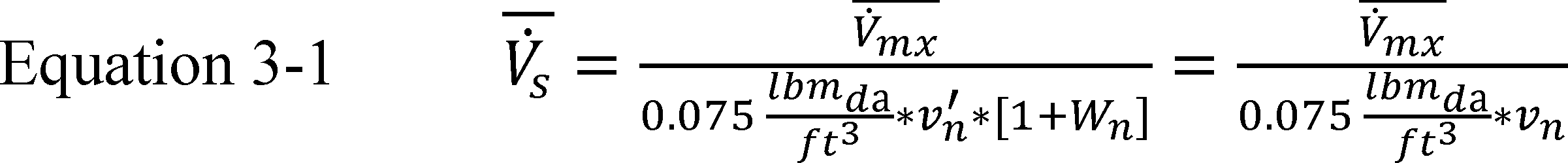
Where:
V̇̅s = air volume rate of standard (dry) air, (ft3/min)da
V̇̅mx = air volume rate of the air-water vapor mixture, (ft3/min)mx
vn′ = specific volume of air-water vapor mixture at the nozzle, ft3 per lbm of the air-water vapor mixture
Wn = humidity ratio at the nozzle, lbm of water vapor per lbm of dry air
0.075 = the density associated with standard (dry) air, (lbm/ft3)
vn = specific volume of the dry air portion of the mixture evaluated at the dry-bulb temperature, vapor content, and barometric pressure existing at the nozzle, ft3 per lbm of dry air.
In the first printing of ANSI/ASHRAE 37-2009, the second IP equation for Qmi should read
3.1.7 Test Sequence
Before making test measurements used to calculate performance, operate the equipment for the “break-in” period specified in the certification report, which may not exceed 20 hours. Each compressor of the unit must undergo this “break-in” period. When testing a ducted unit (except if a heating-only heat pump), conduct the A or A2 Test first to establish the cooling full-load air volume rate. For ducted heat pumps where the heating and cooling full-load air volume rates are different, make the first heating mode test one that requires the heating full-load air volume rate. For ducted heating-only heat pumps, conduct the H1 or H12 Test first to establish the heating full-load air volume rate. When conducting a cyclic test, always conduct it immediately after the steady-state test that requires the same test conditions. For variable-speed systems, the first test using the cooling minimum air volume rate should precede the EV Test, and the first test using the heating minimum air volume rate must precede the H2V Test. The test laboratory makes all other decisions on the test sequence.
3.1.8 Requirement for the Air Temperature Distribution Leaving the Indoor Coil
For at least the first cooling mode test and the first heating mode test, monitor the temperature distribution of the air leaving the indoor coil using the grid of individual sensors described in sections 2.5 and 2.5.4 of this appendix. For the 30-minute data collection interval used to determine capacity, the maximum spread among the outlet dry bulb temperatures from any data sampling must not exceed 1.5 °F. Install the mixing devices described in section 2.5.4.2 of this appendix to minimize the temperature spread.
3.1.9 Requirement for the Air Temperature Distribution Entering the Outdoor Coil
Monitor the temperatures of the air entering the outdoor coil using air sampling devices and/or temperature sensor grids, maintaining the required tolerances, if applicable, as described in section 2.11 of this appendix.
3.1.10 Control of Auxiliary Resistive Heating Elements
Except as noted, disable heat pump resistance elements used for heating indoor air at all times, including during defrost cycles and if they are normally regulated by a heat comfort controller. For heat pumps equipped with a heat comfort controller, enable the heat pump resistance elements only during the below-described, short test. For single-speed heat pumps covered under section 3.6.1 of this appendix, the short test follows the H1 or, if conducted, the H1C Test. For two-capacity heat pumps and heat pumps covered under section 3.6.2 of this appendix, the short test follows the H12 Test. Set the heat comfort controller to provide the maximum supply air temperature. With the heat pump operating and while maintaining the heating full-load air volume rate, measure the temperature of the air leaving the indoor-side beginning 5 minutes after activating the heat comfort controller. Sample the outlet dry-bulb temperature at regular intervals that span 5 minutes or less. Collect data for 10 minutes, obtaining at least 3 samples. Calculate the average outlet temperature over the 10-minute interval, TCC.
3.2 Cooling Mode Tests for Different Types of Air Conditioners and Heat Pumps
3.2.1 Tests for a System Having a Single-Speed Compressor and Fixed Cooling Air Volume Rate
This set of tests is for single-speed-compressor units that do not have a cooling minimum air volume rate or a cooling intermediate air volume rate that is different than the cooling full load air volume rate. Conduct two steady-state wet coil tests, the A and B Tests. Use the two optional dry-coil tests, the steady-state C Test and the cyclic D Test, to determine the cooling mode cyclic degradation coefficient, CDc. If the two optional tests are conducted but yield a tested CDc that exceeds the default CDc or if the two optional tests are not conducted, assign CDc the default value of 0.25 (for outdoor units with no match) or 0.20 (for all other systems). Table 5 specifies test conditions for these four tests.
Table 5 - Cooling Mode Test Conditions for Units Having a Single-Speed Compressor and a Fixed Cooling Air Volume Rate
| Test description | Air entering indoor unit
temperature ( °F) | Air entering outdoor unit
temperature ( °F) | Cooling air volume rate | ||
|---|---|---|---|---|---|
| Dry bulb | Wet bulb | Dry bulb | Wet bulb | ||
| A Test - required (steady, wet coil) | 80 | 67 | 95 | 1 75 | Cooling full-load.2 |
| B Test - required (steady, wet coil) | 80 | 67 | 82 | 1 65 | Cooling full-load.2 |
| C Test - optional (steady, dry coil) | 80 | (3) | 82 | Cooling full-load.2 | |
| D Test - optional (cyclic, dry coil) | 80 | (3) | 82 | (4). | |
3.2.2 Tests for a Unit Having a Single-Speed Compressor Where the Indoor Section Uses a Single Variable-Speed Variable-Air-Volume Rate Indoor Blower or Multiple Indoor Blowers
3.2.2.1 Indoor Blower Capacity Modulation That Correlates With the Outdoor Dry Bulb Temperature or Systems With a Single Indoor Coil but Multiple Indoor Blowers
Conduct four steady-state wet coil tests: The A2, A1, B2, and B1 tests. Use the two optional dry-coil tests, the steady-state C1 test and the cyclic D1 test, to determine the cooling mode cyclic degradation coefficient, CDc. If the two optional tests are conducted but yield a tested CDc that exceeds the default CDc or if the two optional tests are not conducted, assign CDc the default value of 0.20.
3.2.2.2 Indoor Blower Capacity Modulation Based on Adjusting the Sensible to Total (S/T) Cooling Capacity Ratio
The testing requirements are the same as specified in section 3.2.1 of this appendix and Table 5. Use a cooling full-load air volume rate that represents a normal installation. If performed, conduct the steady-state C Test and the cyclic D Test with the unit operating in the same S/T capacity control mode as used for the B Test.
Table 6 - Cooling Mode Test Conditions for Units With a Single-Speed Compressor That Meet the Section 3.2.2.1 Indoor Unit Requirements
| Test description | Air entering indoor unit
temperature ( °F) | Air entering outdoor unit
temperature ( °F) | Cooling air volume rate | ||
|---|---|---|---|---|---|
| Dry bulb | Wet bulb | Dry bulb | Wet bulb | ||
| A2 Test - required (steady, wet coil) | 80 | 67 | 95 | 1 75 | Cooling full-load.2 |
| A1 Test - required (steady, wet coil) | 80 | 67 | 95 | 1 75 | Cooling minimum.3 |
| B2 Test - required (steady, wet coil) | 80 | 67 | 82 | 1 65 | Cooling full-load.2 |
| B1 Test - required (steady, wet coil) | 80 | 67 | 82 | 1 65 | Cooling minimum.3 |
| C1 Test4 - optional (steady, dry coil) | 80 | (4) | 82 | Cooling minimum.3 | |
| D1 Test4 - optional (cyclic, dry coil) | 80 | (4) | 82 | (5). | |
3.2.3 Tests for a Unit Having a Two-Capacity Compressor (See Section 1.2 of This Appendix, Definitions)
a. Conduct four steady-state wet coil tests: the A2, B2, B1, and F1 Tests. Use the two optional dry-coil tests, the steady-state C1 Test and the cyclic D1 Test, to determine the cooling-mode cyclic-degradation coefficient, CDc. If the two optional tests are conducted but yield a tested CDc that exceeds the default CDc or if the two optional tests are not conducted, assign CDc the default value of 0.20. Table 6 specifies test conditions for these six tests.
b. For units having a variable speed indoor blower that is modulated to adjust the sensible to total (S/T) cooling capacity ratio, use cooling full-load and cooling minimum air volume rates that represent a normal installation. Additionally, if conducting the dry-coil tests, operate the unit in the same S/T capacity control mode as used for the B1 Test.
c. Test two-capacity, northern heat pumps (see section 1.2 of this appendix, Definitions) in the same way as a single speed heat pump with the unit operating exclusively at low compressor capacity (see section 3.2.1 of this appendix and Table 5).
d. If a two-capacity air conditioner or heat pump locks out low-capacity operation at higher outdoor temperatures, then use the two dry-coil tests, the steady-state C2 Test and the cyclic D2 Test, to determine the cooling-mode cyclic-degradation coefficient that only applies to on/off cycling from high capacity, CDc(k=2). If the two optional tests are conducted but yield a tested CDc (k = 2) that exceeds the default CDc (k = 2) or if the two optional tests are not conducted, assign CDc (k = 2) the default value. The default CDc(k=2) is the same value as determined or assigned for the low-capacity cyclic-degradation coefficient, CDc [or equivalently, CDc(k=1)].
Table 7 - Cooling Mode Test Conditions for Units Having a Two-Capacity Compressor
| Test description | Air entering indoor unit temperature ( °F) | Air entering outdoor unit temperature ( °F) | Compressor
capacity | Cooling air volume rate | ||
|---|---|---|---|---|---|---|
| Dry bulb | Wet bulb | Dry bulb | Wet bulb | |||
| A2 Test - required (steady, wet coil) | 80 | 67 | 95 | 1 75 | High | Cooling Full-Load.2 |
| B2 Test - required (steady, wet coil) | 80 | 67 | 82 | 1 65 | High | Cooling Full-Load.2 |
| B1 Test - required (steady, wet coil) | 80 | 67 | 82 | 1 65 | Low | Cooling Minimum.3 |
| C2 Test - optional (steady, dry-coil) | 80 | (4) | 82 | High | Cooling Full-Load.2 | |
| D2 Test - optional (cyclic, dry-coil) | 80 | (4) | 82 | High | (5). | |
| C1 Test - optional (steady, dry-coil) | 80 | (4) | 82 | Low | Cooling Minimum.3 | |
| D1 Test - optional (cyclic, dry-coil) | 80 | (4) | 82 | Low | (6). | |
| F1 Test - required (steady, wet coil) | 80 | 67 | 67 | 1 53.5 | Low | Cooling Minimum.3 |
3.2.4 Tests for a Unit Having a Variable-Speed Compressor
a. Conduct five steady-state wet coil tests: The A2, EV, B2, B1, and F1 Tests. Use the two optional dry-coil tests, the steady-state G1 Test and the cyclic I1 Test, to determine the cooling mode cyclic degradation coefficient, CDc. If the two optional tests are conducted but yield a tested CDc that exceeds the default CDc or if the two optional tests are not conducted, assign CDc the default value of 0.25. Table 8 specifies test conditions for these seven tests. The compressor shall operate at the same cooling full speed, measured by RPM or power input frequency (Hz), for both the A2 and B2 tests. The compressor shall operate at the same cooling minimum speed, measured by RPM or power input frequency (Hz), for the B1, F1, G1, and I1 tests. Determine the cooling intermediate compressor speed cited in Table 8 using:

where a tolerance of plus 5 percent or the next higher inverter frequency step from that calculated is allowed.
b. For units that modulate the indoor blower speed to adjust the sensible to total (S/T) cooling capacity ratio, use cooling full-load, cooling intermediate, and cooling minimum air volume rates that represent a normal installation. Additionally, if conducting the dry-coil tests, operate the unit in the same S/T capacity control mode as used for the F1 Test.
c. For multiple-split air conditioners and heat pumps (except where noted), the following procedures supersede the above requirements: For all Table 8 tests specified for a minimum compressor speed, at least one indoor unit must be turned off. The manufacturer shall designate the particular indoor unit(s) that is turned off. The manufacturer must also specify the compressor speed used for the Table 8 EV Test, a cooling-mode intermediate compressor speed that falls within 1⁄4 and 3⁄4 of the difference between the full and minimum cooling-mode speeds. The manufacturer should prescribe an intermediate speed that is expected to yield the highest EER for the given EV Test conditions and bracketed compressor speed range. The manufacturer can designate that one or more indoor units are turned off for the EV Test.
Table 8 - Cooling Mode Test Condition for Units Having a Variable-Speed Compressor
| Test description | Air entering indoor unit
temperature ( °F) | Air entering outdoor unit
temperature ( °F) | Compressor speed | Cooling air
volume rate | ||
|---|---|---|---|---|---|---|
| Dry bulb | Wet bulb | Dry bulb | Wet bulb | |||
| A2 Test - required (steady, wet coil) | 80 | 67 | 95 | 1 75 | Cooling Full | Cooling Full-Load.2 |
| B2 Test - required (steady, wet coil) | 80 | 67 | 82 | 1 65 | Cooling Full | Cooling Full-Load.2 |
| EV Test - required (steady, wet coil) | 80 | 67 | 87 | 1 69 | Cooling Intermediate | Cooling Intermediate.3 |
| B1 Test - required (steady, wet coil) | 80 | 67 | 82 | 1 65 | Cooling Minimum | Cooling Minimum.4 |
| F1 Test - required (steady, wet coil) | 80 | 67 | 67 | 1 53.5 | Cooling Minimum | Cooling Minimum.4 |
| G1 Test5 - optional (steady, dry-coil) | 80 | (6) | 67 | Cooling Minimum | Cooling Minimum.4 | |
| I1 Test5 - optional (cyclic, dry-coil) | 80 | (6) | 67 | Cooling Minimum | (6). | |
3.2.5 Cooling Mode Tests for Northern Heat Pumps With Triple-Capacity Compressors
Test triple-capacity, northern heat pumps for the cooling mode in the same way as specified in section 3.2.3 of this appendix for units having a two-capacity compressor.
3.2.6 Tests for an Air Conditioner or Heat Pump Having a Single Indoor Unit Having Multiple Indoor Blowers and Offering Two Stages of Compressor Modulation
Conduct the cooling mode tests specified in section 3.2.3 of this appendix.
3.3 Test Procedures for Steady-State Wet Coil Cooling Mode Tests (the A, A2, A1, B, B2, B1, EV, and F1 Tests)
a. For the pretest interval, operate the test room reconditioning apparatus and the unit to be tested until maintaining equilibrium conditions for at least 30 minutes at the specified section 3.2 test conditions. Use the exhaust fan of the airflow measuring apparatus and, if installed, the indoor blower of the test unit to obtain and then maintain the indoor air volume rate and/or external static pressure specified for the particular test. Continuously record (see section 1.2 of this appendix, Definitions):
(1) The dry-bulb temperature of the air entering the indoor coil,
(2) The water vapor content of the air entering the indoor coil,
(3) The dry-bulb temperature of the air entering the outdoor coil, and
(4) For the section 2.2.4 of this appendix cases where its control is required, the water vapor content of the air entering the outdoor coil.
Refer to section 3.11 of this appendix for additional requirements that depend on the selected secondary test method.
b. After satisfying the pretest equilibrium requirements, make the measurements specified in Table 3 of ANSI/ASHRAE 37-2009 for the indoor air enthalpy method and the user-selected secondary method. Make said Table 3 measurements at equal intervals that span 5 minutes or less. Continue data sampling until reaching a 30-minute period (e.g., seven consecutive 5-minute samples) where the test tolerances specified in Table 9 are satisfied. For those continuously recorded parameters, use the entire data set from the 30-minute interval to evaluate Table 9 compliance. Determine the average electrical power consumption of the air conditioner or heat pump over the same 30-minute interval.
c. Calculate indoor-side total cooling capacity and sensible cooling capacity as specified in sections 7.3.3.1 and 7.3.3.3 of ANSI/ASHRAE 37-2009 (incorporated by reference, see § 430.3). To calculate capacity, use the averages of the measurements (e.g. inlet and outlet dry bulb and wet bulb temperatures measured at the psychrometers) that are continuously recorded for the same 30-minute interval used as described above to evaluate compliance with test tolerances. Do not adjust the parameters used in calculating capacity for the permitted variations in test conditions. Evaluate air enthalpies based on the measured barometric pressure. Use the values of the specific heat of air given in section 7.3.3.1 of ANSI/ASHRAE 37-2009 (incorporated by reference, see § 430.3) for calculation of the sensible cooling capacities. Assign the average total space cooling capacity, average sensible cooling capacity, and electrical power consumption over the 30-minute data collection interval to the variables Q̇ck(T), Q̇sck(T) and Ėck(T), respectively. For these three variables, replace the “T” with the nominal outdoor temperature at which the test was conducted. The superscript k is used only when testing multi-capacity units.
Use the superscript k=2 to denote a test with the unit operating at high capacity or full speed, k=1 to denote low capacity or minimum speed, and k=v to denote the intermediate speed.
d. For coil-only system tests, decrease Q̇ck(T) by

and increase Ėck(T) by,
where Vs is the average measured indoor air volume rate expressed in units of cubic feet per minute of standard air (scfm).
Table 9 - Test Operating and Test Condition Tolerances for Section 3.3 Steady-State Wet Coil Cooling Mode Tests and Section 3.4 Dry Coil Cooling Mode Tests
| Test operating
tolerance1 | Test condition
tolerance1 | |
|---|---|---|
| Indoor dry-bulb, °F | ||
| Entering temperature | 2.0 | 0.5 |
| Leaving temperature | 2.0 | |
| Indoor wet-bulb, °F | ||
| Entering temperature | 1.0 | 2 0.3 |
| Leaving temperature | 2 1.0 | |
| Outdoor dry-bulb, °F | ||
| Entering temperature | 2.0 | 0.5 |
| Leaving temperature | 3 2.0 | |
| Outdoor wet-bulb, °F | ||
| Entering temperature | 1.0 | 4 0.3 |
| Leaving temperature | 3 1.0 | |
| External resistance to airflow, inches of water | 0.05 | 5 0.02 |
| Electrical voltage, % of rdg. | 2.0 | 1.5 |
| Nozzle pressure drop, % of rdg. | 2.0 |
e. For air conditioners and heat pumps having a constant-air-volume-rate indoor blower, the five additional steps listed below are required if the average of the measured external static pressures exceeds the applicable sections 3.1.4 minimum (or target) external static pressure (ΔPmin) by 0.03 inches of water or more.
(1) Measure the average power consumption of the indoor blower motor (Ėfan,1) and record the corresponding external static pressure (ΔP1) during or immediately following the 30-minute interval used for determining capacity.
(2) After completing the 30-minute interval and while maintaining the same test conditions, adjust the exhaust fan of the airflow measuring apparatus until the external static pressure increases to approximately ΔP1 + (ΔP1−ΔPmin).
(3) After re-establishing steady readings of the fan motor power and external static pressure, determine average values for the indoor blower power (Ėfan,2) and the external static pressure (ΔP2) by making measurements over a 5-minute interval.
(4) Approximate the average power consumption of the indoor blower motor at ΔPmin using linear extrapolation:
(5) Increase the total space cooling capacity, Q̇ck(T), by the quantity (Ėfan,1−Ėfan,min), when expressed on a Btu/h basis. Decrease the total electrical power, Ėck(T), by the same fan power difference, now expressed in watts.
3.4 Test Procedures for the Steady-State Dry-Coil Cooling-Mode Tests (the C, C1, C2, and G1 Tests)
a. Except for the modifications noted in this section, conduct the steady-state dry coil cooling mode tests as specified in section 3.3 of this appendix for wet coil tests. Prior to recording data during the steady-state dry coil test, operate the unit at least one hour after achieving dry coil conditions. Drain the drain pan and plug the drain opening. Thereafter, the drain pan should remain completely dry.
b. Denote the resulting total space cooling capacity and electrical power derived from the test as Q̇ss,dry and Ėss,dry. With regard to a section 3.3 deviation, do not adjust Q̇ss,dry for duct losses (i.e., do not apply section 7.3.3.3 of ANSI/ASHRAE 37-2009). In preparing for the section 3.5 cyclic tests of this appendix, record the average indoor-side air volume rate, V, specific heat of the air, Cp,a (expressed on dry air basis), specific volume of the air at the nozzles, v′n, humidity ratio at the nozzles, Wn, and either pressure difference or velocity pressure for the flow nozzles. For units having a variable-speed indoor blower (that provides either a constant or variable air volume rate) that will or may be tested during the cyclic dry coil cooling mode test with the indoor blower turned off (see section 3.5 of this appendix), include the electrical power used by the indoor blower motor among the recorded parameters from the 30-minute test.
c. If the temperature sensors used to provide the primary measurement of the indoor-side dry bulb temperature difference during the steady-state dry-coil test and the subsequent cyclic dry-coil test are different, include measurements of the latter sensors among the regularly sampled data. Beginning at the start of the 30-minute data collection period, measure and compute the indoor-side air dry-bulb temperature difference using both sets of instrumentation, ΔT (Set SS) and ΔT (Set CYC), for each equally spaced data sample. If using a consistent data sampling rate that is less than 1 minute, calculate and record minutely averages for the two temperature differences. If using a consistent sampling rate of one minute or more, calculate and record the two temperature differences from each data sample. After having recorded the seventh (i=7) set of temperature differences, calculate the following ratio using the first seven sets of values:
Each time a subsequent set of temperature differences is recorded (if sampling more frequently than every 5 minutes), calculate FCD using the most recent seven sets of values. Continue these calculations until the 30-minute period is completed or until a value for FCD is calculated that falls outside the allowable range of 0.94-1.06. If the latter occurs, immediately suspend the test and identify the cause for the disparity in the two temperature difference measurements. Recalibration of one or both sets of instrumentation may be required. If all the values for FCD are within the allowable range, save the final value of the ratio from the 30-minute test as FCD*. If the temperature sensors used to provide the primary measurement of the indoor-side dry bulb temperature difference during the steady-state dry-coil test and the subsequent cyclic dry-coil test are the same, set FCD*= 1.
3.5 Test Procedures for the Cyclic Dry-Coil Cooling-Mode Tests (the D, D1, D2, and I1 Tests)
After completing the steady-state dry-coil test, remove the outdoor air enthalpy method test apparatus, if connected, and begin manual OFF/ON cycling of the unit's compressor. The test set-up should otherwise be identical to the set-up used during the steady-state dry coil test. When testing heat pumps, leave the reversing valve during the compressor OFF cycles in the same position as used for the compressor ON cycles, unless automatically changed by the controls of the unit. For units having a variable-speed indoor blower, the manufacturer has the option of electing at the outset whether to conduct the cyclic test with the indoor blower enabled or disabled. Always revert to testing with the indoor blower disabled if cyclic testing with the fan enabled is unsuccessful.
a. For all cyclic tests, the measured capacity must be adjusted for the thermal mass stored in devices and connections located between measured points. Follow the procedure outlined in section 7.4.3.4.5 of ASHRAE 116-2010 (incorporated by reference, see § 430.3) to ensure any required measurements are taken.
b. For units having a single-speed or two-capacity compressor, cycle the compressor OFF for 24 minutes and then ON for 6 minutes (Δτcyc,dry = 0.5 hours). For units having a variable-speed compressor, cycle the compressor OFF for 48 minutes and then ON for 12 minutes (Δτcyc,dry = 1.0 hours). Repeat the OFF/ON compressor cycling pattern until the test is completed. Allow the controls of the unit to regulate cycling of the outdoor fan. If an upturned duct is used, measure the dry-bulb temperature at the inlet of the device at least once every minute and ensure that its test operating tolerance is within 1.0 °F for each compressor OFF period.
c. Sections 3.5.1 and 3.5.2 of this appendix specify airflow requirements through the indoor coil of ducted and non-ducted indoor units, respectively. In all cases, use the exhaust fan of the airflow measuring apparatus (covered under section 2.6 of this appendix) along with the indoor blower of the unit, if installed and operating, to approximate a step response in the indoor coil airflow. Regulate the exhaust fan to quickly obtain and then maintain the flow nozzle static pressure difference or velocity pressure at the same value as was measured during the steady-state dry coil test. The pressure difference or velocity pressure should be within 2 percent of the value from the steady-state dry coil test within 15 seconds after airflow initiation. For units having a variable-speed indoor blower that ramps when cycling on and/or off, use the exhaust fan of the airflow measuring apparatus to impose a step response that begins at the initiation of ramp up and ends at the termination of ramp down.
d. For units having a variable-speed indoor blower, conduct the cyclic dry coil test using the pull-thru approach described below if any of the following occur when testing with the fan operating:
(1) The test unit automatically cycles off;
(2) Its blower motor reverses; or
(3) The unit operates for more than 30 seconds at an external static pressure that is 0.1 inches of water or more higher than the value measured during the prior steady-state test.
For the pull-thru approach, disable the indoor blower and use the exhaust fan of the airflow measuring apparatus to generate the specified flow nozzles static pressure difference or velocity pressure. If the exhaust fan cannot deliver the required pressure difference because of resistance created by the unpowered indoor blower, temporarily remove the indoor blower.
e. Conduct three complete compressor OFF/ON cycles with the test tolerances given in Table 10 satisfied. Calculate the degradation coefficient CD for each complete cycle. If all three CD values are within 0.02 of the average CD then stability has been achieved, and the highest CD value of these three shall be used. If stability has not been achieved, conduct additional cycles, up to a maximum of eight cycles total, until stability has been achieved between three consecutive cycles. Once stability has been achieved, use the highest CD value of the three consecutive cycles that establish stability. If stability has not been achieved after eight cycles, use the highest CD from cycle one through cycle eight, or the default CD, whichever is lower.
f. With regard to the Table 10 parameters, continuously record the dry-bulb temperature of the air entering the indoor and outdoor coils during periods when air flows through the respective coils. Sample the water vapor content of the indoor coil inlet air at least every 2 minutes during periods when air flows through the coil. Record external static pressure and the air volume rate indicator (either nozzle pressure difference or velocity pressure) at least every minute during the interval that air flows through the indoor coil. (These regular measurements of the airflow rate indicator are in addition to the required measurement at 15 seconds after flow initiation.) Sample the electrical voltage at least every 2 minutes beginning 30 seconds after compressor start-up. Continue until the compressor, the outdoor fan, and the indoor blower (if it is installed and operating) cycle off.
g. For ducted units, continuously record the dry-bulb temperature of the air entering (as noted above) and leaving the indoor coil. Or if using a thermopile, continuously record the difference between these two temperatures during the interval that air flows through the indoor coil. For non-ducted units, make the same dry-bulb temperature measurements beginning when the compressor cycles on and ending when indoor coil airflow ceases.
h. Integrate the electrical power over complete cycles of length Δτcyc,dry. For ducted blower coil systems tested with the unit's indoor blower operating for the cycling test, integrate electrical power from indoor blower OFF to indoor blower OFF. For all other ducted units and for non-ducted units, integrate electrical power from compressor OFF to compressor OFF. (Some cyclic tests will use the same data collection intervals to determine the electrical energy and the total space cooling. For other units, terminate data collection used to determine the electrical energy before terminating data collection used to determine total space cooling.)
Table 10 - Test Operating and Test Condition Tolerances for Cyclic Dry Coil Cooling Mode Tests
| Test operating tolerance1 | Test condition tolerance1 | |
|---|---|---|
| Indoor entering dry-bulb temperature,2 °F | 2.0 | 0.5 |
| Indoor entering wet-bulb temperature, °F | (3) | |
| Outdoor entering dry-bulb temperature,2 °F | 2.0 | 0.5 |
| External resistance to airflow,2 inches of water | 0.05 | |
| Airflow nozzle pressure difference or velocity pressure,2 % of reading | 2.0 | 4 2.0 |
| Electrical voltage,5 % of rdg | 2.0 | 1.5 |
If the Table 10 tolerances are satisfied over the complete cycle, record the measured electrical energy consumption as ecyc,dry and express it in units of watt-hours. Calculate the total space cooling delivered, qcyc,dry, in units of Btu using,

Where,
V, Cp,a, vn′ (or vn), Wn, and FCD* are the values recorded during the section 3.4 dry coil steady-state test and
Tal(τ) = dry bulb temperature of the air entering the indoor coil at time τ, °F.
Ta2(τ) = dry bulb temperature of the air leaving the indoor coil at time τ, °F.
τ1 = for ducted units, the elapsed time when airflow is initiated through the indoor coil; for non-ducted units, the elapsed time when the compressor is cycled on, hr.
τ2 = the elapsed time when indoor coil airflow ceases, hr.
Adjust the total space cooling delivered, qcyc,dry, according to calculation method outlined in section 7.4.3.4.5 of ASHRAE 116-2010 (incorporated by reference, see § 430.3).
3.5.1 Procedures When Testing Ducted Systems
The automatic controls that are installed in the test unit must govern the OFF/ON cycling of the air moving equipment on the indoor side (exhaust fan of the airflow measuring apparatus and the indoor blower of the test unit). For ducted coil-only systems rated based on using a fan time-delay relay, control the indoor coil airflow according to the OFF delay listed by the manufacturer in the certification report. For ducted units having a variable-speed indoor blower that has been disabled (and possibly removed), start and stop the indoor airflow at the same instances as if the fan were enabled. For all other ducted coil-only systems, cycle the indoor coil airflow in unison with the cycling of the compressor. If air damper boxes are used, close them on the inlet and outlet side during the OFF period. Airflow through the indoor coil should stop within 3 seconds after the automatic controls of the test unit (act to) de-energize the indoor blower. For ducted coil-only systems (excluding the special case where a variable-speed fan is temporarily removed), increase ecyc,dry by the quantity,

and decrease qcyc,dry by,

where Vs is the average indoor air volume rate from the section 3.4 dry coil steady-state test and is expressed in units of cubic feet per minute of standard air (scfm). For units having a variable-speed indoor blower that is disabled during the cyclic test, increase ecyc,dry and decrease qcyc,dry based on:
a. The product of [τ2 -τ1] and the indoor blower power measured during or following the dry coil steady-state test; or,
b. The following algorithm if the indoor blower ramps its speed when cycling.
(1) Measure the electrical power consumed by the variable-speed indoor blower at a minimum of three operating conditions: At the speed/air volume rate/external static pressure that was measured during the steady-state test, at operating conditions associated with the midpoint of the ramp-up interval, and at conditions associated with the midpoint of the ramp-down interval. For these measurements, the tolerances on the airflow volume or the external static pressure are the same as required for the section 3.4 steady-state test.
(2) For each case, determine the fan power from measurements made over a minimum of 5 minutes.
(3) Approximate the electrical energy consumption of the indoor blower if it had operated during the cyclic test using all three power measurements. Assume a linear profile during the ramp intervals. The manufacturer must provide the durations of the ramp-up and ramp-down intervals. If the test setup instructions included with the unit by the manufacturer specifies a ramp interval that exceeds 45 seconds, use a 45-second ramp interval nonetheless when estimating the fan energy.
3.5.2 Procedures When Testing Non-Ducted Indoor Units
Do not use airflow prevention devices when conducting cyclic tests on non-ducted indoor units. Until the last OFF/ON compressor cycle, airflow through the indoor coil must cycle off and on in unison with the compressor. For the last OFF/ON compressor cycle - the one used to determine ecyc,dry and qcyc,dry - use the exhaust fan of the airflow measuring apparatus and the indoor blower of the test unit to have indoor airflow start 3 minutes prior to compressor cut-on and end three minutes after compressor cutoff. Subtract the electrical energy used by the indoor blower during the 3 minutes prior to compressor cut-on from the integrated electrical energy, ecyc,dry. Add the electrical energy used by the indoor blower during the 3 minutes after compressor cutoff to the integrated cooling capacity, qcyc,dry. For the case where the non-ducted indoor unit uses a variable-speed indoor blower which is disabled during the cyclic test, correct ecyc,dry and qcyc,dry using the same approach as prescribed in section 3.5.1 of this appendix for ducted units having a disabled variable-speed indoor blower.
3.5.3 Cooling-Mode Cyclic-Degradation Coefficient Calculation
Use the two dry-coil tests to determine the cooling-mode cyclic-degradation coefficient, CDc. Append “(k=2)” to the coefficient if it corresponds to a two-capacity unit cycling at high capacity. If the two optional tests are conducted but yield a tested CDc that exceeds the default CDc or if the two optional tests are not conducted, assign CDc the default value of 0.25 for variable-speed compressor systems and outdoor units with no match, and 0.20 for all other systems. The default value for two-capacity units cycling at high capacity, however, is the low-capacity coefficient, i.e., CDc(k=2) = CDc. Evaluate CDc using the above results and those from the section 3.4 dry-coil steady-state test.

where:
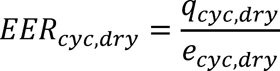
the average energy efficiency ratio during the cyclic dry coil cooling mode test, Btu/W·h
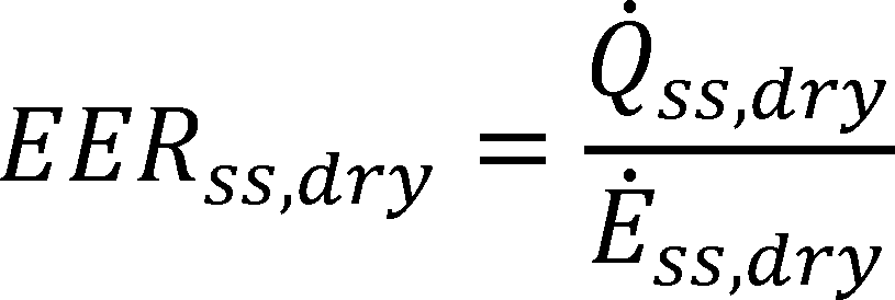
the average energy efficiency ratio during the steady-state dry coil cooling mode test, Btu/W·h
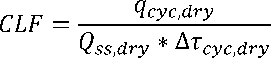
the cooling load factor dimensionless
Round the calculated value for CDc to the nearest 0.01. If CDc is negative, then set it equal to zero.
3.6 Heating Mode Tests for Different Types of Heat Pumps, Including Heating-Only Heat Pumps
3.6.1 Tests for a Heat Pump Having a Single-Speed Compressor and Fixed Heating Air Volume Rate
This set of tests is for single-speed-compressor heat pumps that do not have a heating minimum air volume rate or a heating intermediate air volume rate that is different than the heating full load air volume rate. Conduct the optional high temperature cyclic (H1C) test to determine the heating mode cyclic-degradation coefficient, CDh. If this optional test is conducted but yields a tested CDh that exceeds the default CDh or if the optional test is not conducted, assign CDh the default value of 0.25. Test conditions for the four tests are specified in Table 10.
Table 11 - Heating Mode Test Conditions for Units Having a Single-Speed Compressor and a Fixed-Speed Indoor Blower, a Constant Air Volume Rate Indoor Blower, or No Indoor Blower
| Test description | Air entering indoor unit
temperature ( °F) | Air entering outdoor unit
temperature ( °F) | Heating air volume rate | ||
|---|---|---|---|---|---|
| Dry bulb | Wet bulb | Dry bulb | Wet bulb | ||
| H1 Test (required, steady) | 70 | 60(max) | 47 | 43 | Heating Full-load.1 |
| H1C Test (optional, cyclic) | 70 | 60(max) | 47 | 43 | (2) |
| H2 Test (required) | 70 | 60(max) | 35 | 33 | Heating Full-load.1 |
| H3 Test (required, steady) | 70 | 60(max) | 17 | 15 | Heating Full-load.1 |
3.6.2 Tests for a Heat Pump Having a Single-Speed Compressor and a Single Indoor Unit Having Either (1) a Variable Speed, Variable-Air-Rate Indoor Blower Whose Capacity Modulation Correlates With Outdoor Dry Bulb Temperature or (2) Multiple Indoor Blowers
Conduct five tests: Two high temperature tests (H12 and H11), one frost accumulation test (H22), and two low temperature tests (H32 and H31). Conducting an additional frost accumulation test (H21) is optional. Conduct the optional high temperature cyclic (H1C1) test to determine the heating mode cyclic-degradation coefficient, CDh. If this optional test is conducted but yields a tested CDh that exceeds the default CDh or if the optional test is not conducted, assign CDh the default value of 0.25. Test conditions for the seven tests are specified in Table 12. If the optional H21 test is not performed, use the following equations to approximate the capacity and electrical power of the heat pump at the H21 test conditions:
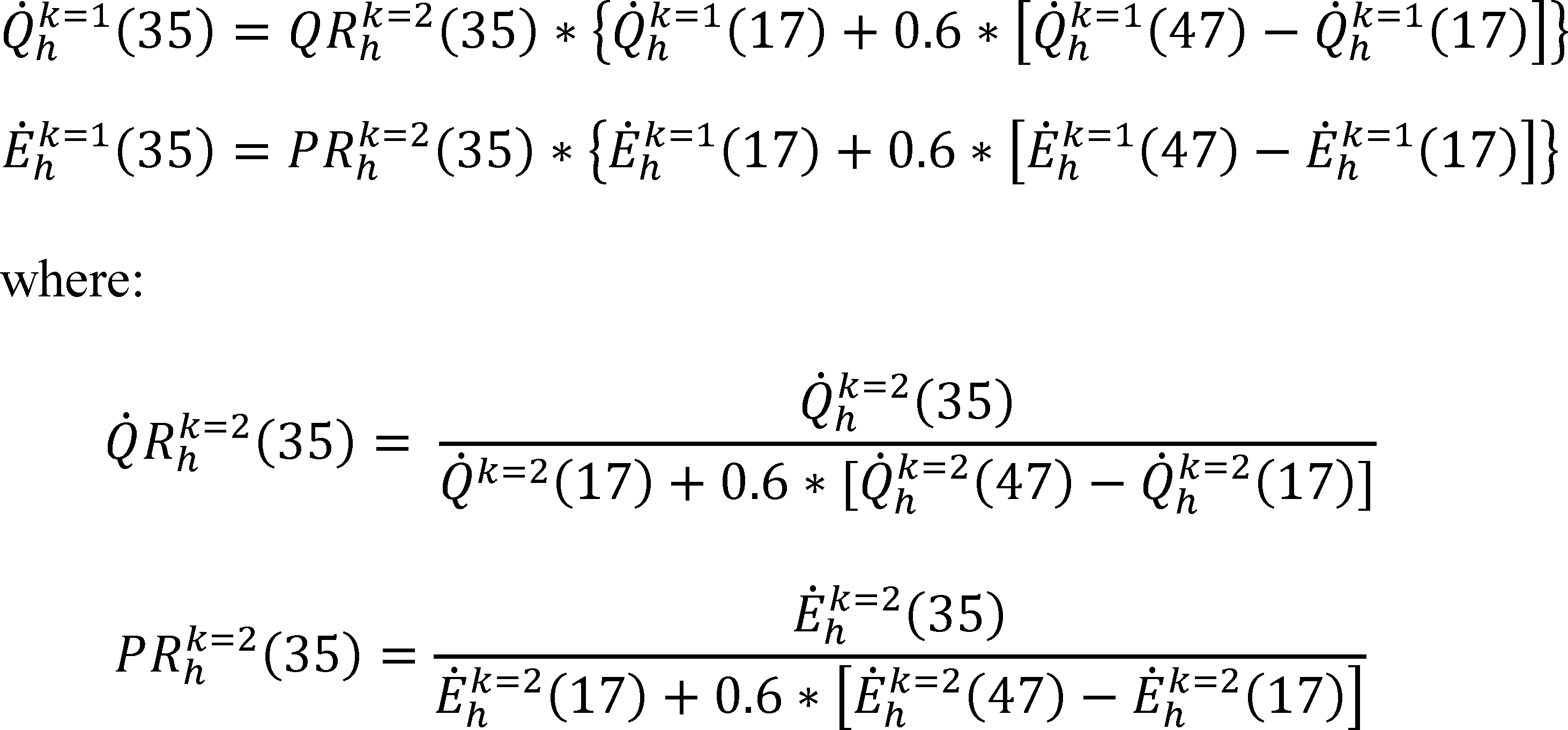
The quantities Q̇hk=2(47), Ėhk=2(47), Q̇hk=1(47), and Ėhk=1(47) are determined from the H12 and H11 tests and evaluated as specified in section 3.7 of this appendix; the quantities Q̇hk=2(35) and Ėhk=2(35) are determined from the H22 test and evaluated as specified in section 3.9 of this appendix; and the quantities Q̇hk=2(17), Ėhk=2(17), Q̇hk=1(17), and Ėhk=1(17), are determined from the H32 and H31 tests and evaluated as specified in section 3.10 of this appendix.
Table 12 - Table Heating Mode Test Conditions for Units With a Single-Speed Compressor That Meet the Section 3.6.2 Indoor Unit Requirements
| Test description | Air entering indoor unit
temperature ( °F) | Air entering outdoor unit
temperature ( °F) | Heating air volume rate | ||
|---|---|---|---|---|---|
| Dry bulb | Wet bulb | Dry bulb | Wet bulb | ||
| H12 Test (required, steady) | 70 | 60(max) | 47 | 43 | Heating Full-load.1 |
| H11 Test (required, steady) | 70 | 60(max) | 47 | 43 | Heating Minimum.2 |
| H1C1 Test (optional, cyclic) | 70 | 60(max) | 47 | 43 | (3) |
| H22 Test (required) | 70 | 60(max) | 35 | 33 | Heating Full-load.1 |
| H21 Test (optional) | 70 | 60(max) | 35 | 33 | Heating Minimum.2 |
| H32 Test (required, steady) | 70 | 60(max) | 17 | 15 | Heating Full-load.1 |
| H31 Test (required, steady) | 70 | 60(max) | 17 | 15 | Heating Minimum.2 |
3.6.3 Tests for a Heat Pump Having a Two-Capacity Compressor (see section 1.2 of this appendix, Definitions), Including Two-Capacity, Northern Heat Pumps (see section 1.2 of this appendix, Definitions)
a. Conduct one maximum temperature test (H01), two high temperature tests (H12and H11), one frost accumulation test (H22), and one low temperature test (H32). Conduct an additional frost accumulation test (H21) and low temperature test (H31) if both of the following conditions exist:
(1) Knowledge of the heat pump's capacity and electrical power at low compressor capacity for outdoor temperatures of 37 °F and less is needed to complete the section 4.2.3 of this appendix seasonal performance calculations; and
(2) The heat pump's controls allow low-capacity operation at outdoor temperatures of 37 °F and less.
If the above two conditions are met, an alternative to conducting the H21 frost accumulation is to use the following equations to approximate the capacity and electrical power:
Determine the quantities Q̇hk=1 (47) and Ėhk=1 (47) from the H11 test and evaluate them according to section 3.7 of this appendix. Determine the quantities Q̇hk=1 (17) and Ėhk=1 (17) from the H31 test and evaluate them according to section 3.10 of this appendix.
b. Conduct the optional high temperature cyclic test (H1C1) to determine the heating mode cyclic-degradation coefficient, CDh. If this optional test is conducted but yields a tested CDh that exceeds the default CDh or if the optional test is not conducted, assign CDh the default value of 0.25. If a two-capacity heat pump locks out low capacity operation at lower outdoor temperatures, conduct the high temperature cyclic test (H1C2) to determine the high-capacity heating mode cyclic-degradation coefficient, CDh (k=2). If this optional test at high capacity is conducted but yields a tested CDh (k = 2) that exceeds the default CDh (k = 2) or if the optional test is not conducted, assign CDh the default value. The default CDh (k=2) is the same value as determined or assigned for the low-capacity cyclic-degradation coefficient, CDh [or equivalently, CDh (k=1)]. Table 13 specifies test conditions for these nine tests.
Table 13 - Heating Mode Test Conditions for Units Having a Two-Capacity Compressor
| Test description | Air entering indoor unit
temperature ( °F) | Air entering outdoor unit
temperature ( °F) | Compressor capacity | Heating air volume rate | ||
|---|---|---|---|---|---|---|
| Dry bulb | Wet bulb | Dry bulb | Wet bulb | |||
| H01 Test (required, steady) | 70 | 60(max) | 62 | 56.5 | Low | Heating Minimum.1 |
| H12 Test (required, steady) | 70 | 60(max) | 47 | 43 | High | Heating Full-Load.2 |
| H1C2 Test (optional7, cyclic) | 70 | 60(max) | 47 | 43 | High | (3) |
| H11 Test (required) | 70 | 60(max) | 47 | 43 | Low | Heating Minimum.1 |
| H1C1 Test (optional, cyclic) | 70 | 60(max) | 47 | 43 | Low | (4) |
| H22 Test (required) | 70 | 60(max) | 35 | 33 | High | Heating Full-Load.2 |
| H21 Test5 6 (required) | 70 | 60(max) | 35 | 33 | Low | Heating Minimum.1 |
| H32 Test (required, steady) | 70 | 60(max) | 17 | 15 | High | Heating Full-Load.2 |
| H31 Test5 (required, steady) | 70 | 60(max) | 17 | 15 | Low | Heating Minimum.1 |
3.6.4 Tests for a Heat Pump Having a Variable-Speed Compressor
a. Conduct one maximum temperature test (H01), two high temperature tests (H1N and H11), one frost accumulation test (H2V), and one low temperature test (H32). Conducting one or both of the following tests is optional: An additional high temperature test (H12) and an additional frost accumulation test (H22). If desired, conduct the optional maximum temperature cyclic (H0C1) test to determine the heating mode cyclic-degradation coefficient, CDh. If this optional test is conducted but yields a tested CDh that exceeds the default CDh or if the optional test is not conducted, assign CDh the default value of 0.25. Test conditions for the eight tests are specified in Table 14. The compressor shall operate at the same heating full speed, measured by RPM or power input frequency (Hz), for the H12, H22 and H32 tests. For a cooling/heating heat pump, the compressor shall operate for the H1N test at a speed, measured by RPM or power input frequency (Hz), no lower than the speed used in the A2 test if the tested H12 heating capacity is less than the tested cooling capacity in A2 test. The compressor shall operate at the same heating minimum speed, measured by RPM or power input frequency (Hz), for the H01, H1C1, and H11 tests. Determine the heating intermediate compressor speed cited in Table 14 using the heating mode full and minimum compressors speeds and:

Where a tolerance on speed of plus 5 percent or the next higher inverter frequency step from the calculated value is allowed.
b. If the H12 test is conducted, set the 47 °F capacity and power input values used for calculation of HSPF equal to the measured values for that test:

Where:
Q̇hcalck=2(47) and Ėhcalck=2(47) are the capacity and power input representing full-speed operation at 47 °F for the HSPF calculations,
Q̇hk=2(47) is the capacity measured in the H12 test, and
Ėhk=2(47) is the power input measured in the H12 test.
Evaluate the quantities Q̇hk=2(47) and from Ėhk=2(47) according to section 3.7.
Otherwise, if the H1N test is conducted using the same compressor speed (RPM or power input frequency) as the H32 test, set the 47 °F capacity and power input values used for calculation of HSPF equal to the measured values for that test:

Where:
Q̇hcalck=2(47) and Ėhcalck=2(47) are the capacity and power input representing full-speed operation at 47 °F for the HSPF calculations,
Q̇hk=N(47) is the capacity measured in the H1N test, and
Ėhk=N(47) is the power input measured in the H1N test.
Evaluate the quantities Q̇hk=N(47) and from Ėhk=N(47) according to section 3.7.
Otherwise (if no high temperature test is conducted using the same speed (RPM or power input frequency) as the H32 test), calculate the 47 °F capacity and power input values used for calculation of HSPF as follows:

Where:
Q̇hcalck=2(47) and Ėhcalck=2(47) are the capacity and power input representing full-speed operation at 47 °F for the HSPF calculations,
Q̇hk=2(17) is the capacity measured in the H32 test,
Ėhk=2(17) is the power input measured in the H32 test,
CSF is the capacity slope factor, equal to 0.0204/ °F for split systems and 0.0262/ °F for single-package systems, and
PSF is the Power Slope Factor, equal to 0.00455/ °F.
c. If the H22 test is not done, use the following equations to approximate the capacity and electrical power at the H22 test conditions:

Where:
Q̇hcalck=2(47) and Ėhcalck=2(47) are the capacity and power input representing full-speed operation at 47 °F for the HSPF calculations,calculated as described in section b above.
Q̇hk=2(17) and Ėhk=2(17) are the capacity and power input measured in the H32 test.
d. Determine the quantities Q̇hk=2(17) and Ėhk=2(17) from the H32 test, determine the quantities Q̇hk=2(5) and Ėhk=2(5) from the H42 test, and evaluate all four according to section 3.10.
Table 14 - Heating Mode Test Conditions for Units Having a Variable-Speed Compressor
| Test description | Air entering indoor unit
temperature ( °F) | Air entering outdoor unit
temperature ( °F) | Compressor speed | Heating air volume rate | ||
|---|---|---|---|---|---|---|
| Dry bulb | Wet bulb | Dry bulb | Wet bulb | |||
| H01 test (required, steady) | 70 | 60(max) | 62 | 56.5 | Heating minimum | Heating minimum.1 |
| H12 test (optional, steady) | 70 | 60(max) | 47 | 43 | Heating full4 | Heating full-load.3 |
| H11 test (required, steady) | 70 | 60(max) | 47 | 43 | Heating minimum | Heating minimum.1 |
| H1N test (required, steady) | 70 | 60(max) | 47 | 43 | Heating full | Heating full-load.3 |
| H1C1 test (optional, cyclic) | 70 | 60(max) | 47 | 43 | Heating minimum | (2) |
| H22 test (optional) | 70 | 60(max) | 35 | 33 | Heating full4 | Heating full-load.3 |
| H2V test (required) | 70 | 60(max) | 35 | 33 | Heating intermediate | Heating intermediate.5 |
| H32 test (required, steady) | 70 | 60(max) | 17 | 15 | Heating full | Heating full-load.3 |
3.6.5 Additional Test for a Heat Pump Having a Heat Comfort Controller
Test any heat pump that has a heat comfort controller (see section 1.2 of this appendix, Definitions) according to section 3.6.1, 3.6.2, or 3.6.3, whichever applies, with the heat comfort controller disabled. Additionally, conduct the abbreviated test described in section 3.1.10 of this appendix with the heat comfort controller active to determine the system's maximum supply air temperature. (Note: Heat pumps having a variable speed compressor and a heat comfort controller are not covered in the test procedure at this time.)
3.6.6 Heating Mode Tests for Northern Heat Pumps With Triple-Capacity Compressors.
Test triple-capacity, northern heat pumps for the heating mode as follows:
a. Conduct one maximum-temperature test (H01), two high-temperature tests (H12 and H11), one frost accumulation test (H22), two low-temperature tests (H32, H33), and one minimum-temperature test (H43). Conduct an additional frost accumulation test (H21) and low-temperature test (H31) if both of the following conditions exist: (1) Knowledge of the heat pump's capacity and electrical power at low compressor capacity for outdoor temperatures of 37 °F and less is needed to complete the section 4.2.6 seasonal performance calculations; and (2) the heat pump's controls allow low-capacity operation at outdoor temperatures of 37 °F and less. If the above two conditions are met, an alternative to conducting the H21 frost accumulation test to determine Q̇hk=1(35) and Ėhk=1(35) is to use the following equations to approximate this capacity and electrical power:
In evaluating the above equations, determine the quantities Q̇hk=1(47) from the H11 test and evaluate them according to section 3.7 of this appendix. Determine the quantities Q̇hk=1(17) and Ėhk=1(17) from the H31 test and evaluate them according to section 3.10 of this appendix. Use the paired values of Q̇hk=1(35) and Ėhk=1(35) derived from conducting the H21 frost accumulation test and evaluated as specified in section 3.9.1 of this appendix or use the paired values calculated using the above default equations, whichever contribute to a higher Region IV HSPF based on the DHRmin.
b. Conducting a frost accumulation test (H23) with the heat pump operating at its booster capacity is optional. If this optional test is not conducted, determine Q̇hk=3(35) and Ėhk=3(35) using the following equations to approximate this capacity and electrical power:
Where:

Determine the quantities Q̇hk=2(47) and Ėhk=2(47) from the H12 test and evaluate them according to section 3.7 of this appendix. Determine the quantities Q̇hk=2(35) and Ėhk=2(35) from the H22 test and evaluate them according to section 3.9.1 of this appendix. Determine the quantities Q̇hk=2(17) and Ėhk=2(17) from the H32 test, determine the quantities Q̇hk=3(17) and Ėhk=3(17) from the H33 test, and determine the quantities Q̇hk=3(5) and Ėhk=3(5) from the H43 test. Evaluate all six quantities according to section 3.10 of this appendix. Use the paired values of Q̇hk=3(35) and Ėhk=3(35) derived from conducting the H23 frost accumulation test and calculated as specified in section 3.9.1 of this appendix or use the paired values calculated using the above default equations, whichever contribute to a higher Region IV HSPF2 based on the DHRmin.
c. Conduct the optional high-temperature cyclic test (H1C1) to determine the heating mode cyclic-degradation coefficient, CDh. A default value for CDh may be used in lieu of conducting the cyclic. The default value of CDh is 0.25. If a triple-capacity heat pump locks out low capacity operation at lower outdoor temperatures, conduct the high-temperature cyclic test (H1C2) to determine the high-capacity heating mode cyclic-degradation coefficient, CDh (k=2). The default CDh (k=2) is the same value as determined or assigned for the low-capacity cyclic-degradation coefficient, CDh [or equivalently, CDh (k=1)]. Finally, if a triple-capacity heat pump locks out both low and high capacity operation at the lowest outdoor temperatures, conduct the low-temperature cyclic test (H3C3) to determine the booster-capacity heating mode cyclic-degradation coefficient, CDh (k=3). The default CDh (k=3) is the same value as determined or assigned for the high-capacity cyclic-degradation coefficient, CDh [or equivalently, CDh (k=2)]. Table 15 specifies test conditions for all 13 tests.
Table 15 - Heating Mode Test Conditions for Units With a Triple-Capacity Compressor
| Test description | Air entering indoor unit
temperature °F | Air entering outdoor unit
temperature °F | Compressor capacity | Heating air volume rate | ||
|---|---|---|---|---|---|---|
| Dry bulb | Wet bulb | Dry bulb | Wet bulb | |||
| H01 Test (required, steady) | 70 | 60(max) | 62 | 56.5 | Low | Heating Minimum.1 |
| H12 Test (required, steady) | 70 | 60(max) | 47 | 43 | High | Heating Full-Load.2 |
| H1C2 Test (optional,8 cyclic) | 70 | 60(max) | 47 | 43 | High | (3). |
| H11 Test (required) | 70 | 60(max) | 47 | 43 | Low | Heating Minimum.1 |
| H1C1 Test (optional, cyclic) | 70 | 60(max) | 47 | 43 | Low | (4). |
| H23 Test (optional, steady) | 70 | 60(max) | 35 | 33 | Booster | Heating Full-Load.2 |
| H22 Test (required) | 70 | 60(max) | 35 | 33 | High | Heating Full-Load.2 |
| H21 Test (required) | 70 | 60(max) | 35 | 33 | Low | Heating Minimum.1 |
| H33 Test (required, steady) | 70 | 60(max) | 17 | 15 | Booster | Heating Full-Load.2 |
| H3C3 Test5 6 (optional, cyclic) | 70 | 60(max) | 17 | 15 | Booster | (7). |
| H32 Test (required, steady) | 70 | 60(max) | 17 | 15 | High | Heating Full-Load.2 |
| H31 Test5 (required, steady) | 70 | 60(max) | 17 | 15 | Low | Heating Minimum.1 |
| H43 Test (required, steady) | 70 | 60(max) | 5 | 3(max) | Booster | Heating Full-Load.2 |
3.6.7 Tests for a Heat Pump Having a Single Indoor Unit Having Multiple Indoor Blowers and Offering Two Stages of Compressor Modulation
Conduct the heating mode tests specified in section 3.6.3 of this appendix.
3.7 Test Procedures for Steady-State Maximum Temperature and High Temperature Heating Mode Tests (the H01, H1, H12, H11, and H1N Tests)
a. For the pretest interval, operate the test room reconditioning apparatus and the heat pump until equilibrium conditions are maintained for at least 30 minutes at the specified section 3.6 test conditions. Use the exhaust fan of the airflow measuring apparatus and, if installed, the indoor blower of the heat pump to obtain and then maintain the indoor air volume rate and/or the external static pressure specified for the particular test. Continuously record the dry-bulb temperature of the air entering the indoor coil, and the dry-bulb temperature and water vapor content of the air entering the outdoor coil. Refer to section 3.11 of this appendix for additional requirements that depend on the selected secondary test method. After satisfying the pretest equilibrium requirements, make the measurements specified in Table 3 of ANSI/ASHRAE 37-2009 (incorporated by reference, see § 430.3) for the indoor air enthalpy method and the user-selected secondary method. Make said Table 3 measurements at equal intervals that span 5 minutes or less. Continue data sampling until a 30-minute period (e.g., seven consecutive 5-minute samples) is reached where the test tolerances specified in Table 16 are satisfied. For those continuously recorded parameters, use the entire data set for the 30-minute interval when evaluating Table 16 compliance. Determine the average electrical power consumption of the heat pump over the same 30-minute interval.
Table 16 - Test Operating and Test Condition Tolerances for Section 3.7 and Section 3.10 Steady-State Heating Mode Tests
| Test operating
tolerance1 | Test condition
tolerance1 | |
|---|---|---|
| Indoor dry-bulb, °F: | ||
| Entering temperature | 2.0 | 0.5 |
| Leaving temperature | 2.0 | |
| Indoor wet-bulb, °F: | ||
| Entering temperature | 1.0 | |
| Leaving temperature | 1.0 | |
| Outdoor dry-bulb, °F: | ||
| Entering temperature | 2.0 | 0.5 |
| Leaving temperature | 2 2.0 | |
| Outdoor wet-bulb, °F: | ||
| Entering temperature | 1.0 | 0.3 |
| Leaving temperature | 2 1.0 | |
| External resistance to airflow, inches of water | 0.05 | 3 0.02 |
| Electrical voltage, % of rdg | 2.0 | 1.5 |
| Nozzle pressure drop, % of rdg | 2.0 |
b. Calculate indoor-side total heating capacity as specified in sections 7.3.4.1 and 7.3.4.3 of ANSI/ASHRAE 37-2009 (incorporated by reference, see § 430.3). To calculate capacity, use the averages of the measurements (e.g. inlet and outlet dry bulb temperatures measured at the psychrometers) that are continuously recorded for the same 30-minute interval used as described above to evaluate compliance with test tolerances. Do not adjust the parameters used in calculating capacity for the permitted variations in test conditions. Assign the average space heating capacity and electrical power over the 30-minute data collection interval to the variables Q̇hk and Ėhk(T) respectively. The “T” and superscripted “k” are the same as described in section 3.3 of this appendix. Additionally, for the heating mode, use the superscript to denote results from the optional H1N test, if conducted.
c. For coil-only system heat pumps, increase Q̇hk(T) by
where V̇̅s is the average measured indoor air volume rate expressed in units of cubic feet per minute of standard air (scfm). During the 30-minute data collection interval of a high temperature test, pay attention to preventing a defrost cycle. Prior to this time, allow the heat pump to perform a defrost cycle if automatically initiated by its own controls. As in all cases, wait for the heat pump's defrost controls to automatically terminate the defrost cycle. Heat pumps that undergo a defrost should operate in the heating mode for at least 10 minutes after defrost termination prior to beginning the 30-minute data collection interval. For some heat pumps, frost may accumulate on the outdoor coil during a high temperature test. If the indoor coil leaving air temperature or the difference between the leaving and entering air temperatures decreases by more than 1.5 °F over the 30-minute data collection interval, then do not use the collected data to determine capacity. Instead, initiate a defrost cycle. Begin collecting data no sooner than 10 minutes after defrost termination. Collect 30 minutes of new data during which the Table 16 test tolerances are satisfied. In this case, use only the results from the second 30-minute data collection interval to evaluate Q̇hk(47) and Ėhk(47).
d. If conducting the cyclic heating mode test, which is described in section 3.8 of this appendix, record the average indoor-side air volume rate, V̇̅, specific heat of the air, Cp,a (expressed on dry air basis), specific volume of the air at the nozzles, vn′ (or vn), humidity ratio at the nozzles, Wn, and either pressure difference or velocity pressure for the flow nozzles. If either or both of the below criteria apply, determine the average, steady-state, electrical power consumption of the indoor blower motor (Ėfan,1):
(1) The section 3.8 cyclic test will be conducted and the heat pump has a variable-speed indoor blower that is expected to be disabled during the cyclic test; or
(2) The heat pump has a (variable-speed) constant-air volume-rate indoor blower and during the steady-state test the average external static pressure (ΔP1) exceeds the applicable section 3.1.4.4 minimum (or targeted) external static pressure (ΔPmin) by 0.03 inches of water or more.
Determine Ėfan,1 by making measurements during the 30-minute data collection interval, or immediately following the test and prior to changing the test conditions. When the above “2” criteria applies, conduct the following four steps after determining Ėfan,1 (which corresponds to ΔP1):
(i) While maintaining the same test conditions, adjust the exhaust fan of the airflow measuring apparatus until the external static pressure increases to approximately ΔP1 + (ΔP1 − ΔPmin).
(ii) After re-establishing steady readings for fan motor power and external static pressure, determine average values for the indoor blower power (Ėfan,2) and the external static pressure (ΔP2) by making measurements over a 5-minute interval.
(iii) Approximate the average power consumption of the indoor blower motor if the 30-minute test had been conducted at ΔPmin using linear extrapolation:

(iv) Decrease the total space heating capacity, Q̇hk(T), by the quantity (Ėfan,1 − Ėfan,min), when expressed on a Btu/h basis. Decrease the total electrical power, Ėhk(T) by the same fan power difference, now expressed in watts.
e. If the temperature sensors used to provide the primary measurement of the indoor-side dry bulb temperature difference during the steady-state dry-coil test and the subsequent cyclic dry-coil test are different, include measurements of the latter sensors among the regularly sampled data. Beginning at the start of the 30-minute data collection period, measure and compute the indoor-side air dry-bulb temperature difference using both sets of instrumentation, ΔT (Set SS) and ΔT (Set CYC), for each equally spaced data sample. If using a consistent data sampling rate that is less than 1 minute, calculate and record minutely averages for the two temperature differences. If using a consistent sampling rate of one minute or more, calculate and record the two temperature differences from each data sample. After having recorded the seventh (i=7) set of temperature differences, calculate the following ratio using the first seven sets of values:
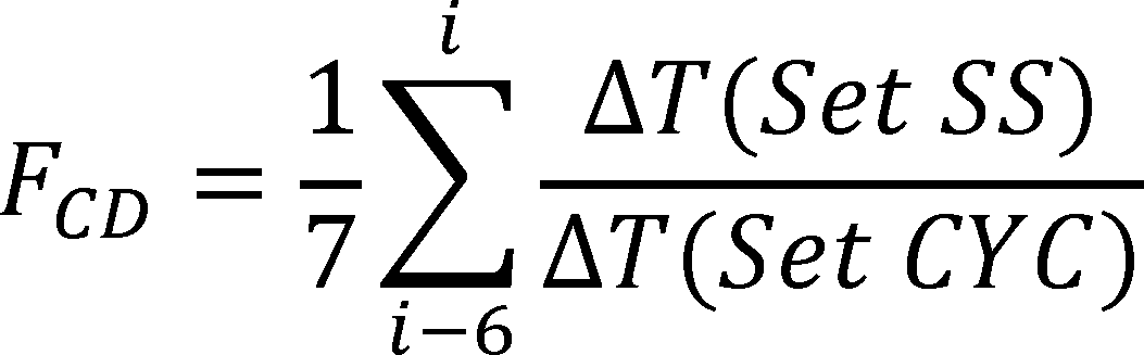
Each time a subsequent set of temperature differences is recorded (if sampling more frequently than every 5 minutes), calculate FCD using the most recent seven sets of values. Continue these calculations until the 30-minute period is completed or until a value for FCD is calculated that falls outside the allowable range of 0.94-1.06. If the latter occurs, immediately suspend the test and identify the cause for the disparity in the two temperature difference measurements. Recalibration of one or both sets of instrumentation may be required. If all the values for FCD are within the allowable range, save the final value of the ratio from the 30-minute test as FCD*. If the temperature sensors used to provide the primary measurement of the indoor-side dry bulb temperature difference during the steady-state dry-coil test and the subsequent cyclic dry-coil test are the same, set FCD*= 1.
3.8 Test Procedures for the Cyclic Heating Mode Tests (the H0C1, H1C, H1C1 and H1C2 Tests)
a. Except as noted below, conduct the cyclic heating mode test as specified in section 3.5 of this appendix. As adapted to the heating mode, replace section 3.5 references to “the steady-state dry coil test” with “the heating mode steady-state test conducted at the same test conditions as the cyclic heating mode test.” Use the test tolerances in Table 17 rather than Table 10. Record the outdoor coil entering wet-bulb temperature according to the requirements given in section 3.5 of this appendix for the outdoor coil entering dry-bulb temperature. Drop the subscript “dry” used in variables cited in section 3.5 of this appendix when referring to quantities from the cyclic heating mode test. Determine the total space heating delivered during the cyclic heating test, qcyc, as specified in section 3.5 of this appendix except for making the following changes:
(1) When evaluating Equation 3.5-1, use the values of V̇̅, Cp,a,vn′, (or vn), and Wn that were recorded during the section 3.7 steady-state test conducted at the same test conditions.
(2) Calculate Γ using

where FCD* is the value recorded during the section 3.7 steady-state test conducted at the same test condition.
b. For ducted coil-only system heat pumps (excluding the special case where a variable-speed fan is temporarily removed), increase qcyc by the amount calculated using Equation 3.5-3. Additionally, increase ecyc by the amount calculated using Equation 3.5-2. In making these calculations, use the average indoor air volume rate (V̇̅s) determined from the section 3.7 steady-state heating mode test conducted at the same test conditions.
c. For non-ducted heat pumps, subtract the electrical energy used by the indoor blower during the 3 minutes after compressor cutoff from the non-ducted heat pump's integrated heating capacity, qcyc.
d. If a heat pump defrost cycle is manually or automatically initiated immediately prior to or during the OFF/ON cycling, operate the heat pump continuously until 10 minutes after defrost termination. After that, begin cycling the heat pump immediately or delay until the specified test conditions have been re-established. Pay attention to preventing defrosts after beginning the cycling process. For heat pumps that cycle off the indoor blower during a defrost cycle, make no effort here to restrict the air movement through the indoor coil while the fan is off. Resume the OFF/ON cycling while conducting a minimum of two complete compressor OFF/ON cycles before determining qcyc and ecyc.
3.8.1 Heating Mode Cyclic-Degradation Coefficient Calculation
Use the results from the required cyclic test and the required steady-state test that were conducted at the same test conditions to determine the heating mode cyclic-degradation coefficient CDh. Add “(k=2)” to the coefficient if it corresponds to a two-capacity unit cycling at high capacity. For the below calculation of the heating mode cyclic degradation coefficient, do not include the duct loss correction from section 7.3.3.3 of ANSI/ASHRAE 37-2009 (incorporated by reference, see § 430.3) in determining Q̇hk(Tcyc) (or qcyc). If the optional cyclic test is conducted but yields a tested CDh that exceeds the default CDh or if the optional test is not conducted, assign CDh the default value of 0.25. The default value for two-capacity units cycling at high capacity, however, is the low-capacity coefficient, i.e., CDh (k=2) = CDh. The tested CDh is calculated as follows:

where:
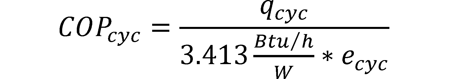
the average coefficient of performance during the cyclic heating mode test, dimensionless.
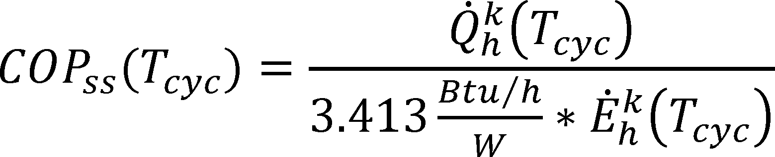
the average coefficient of performance during the steady-state heating mode test conducted at the same test conditions - i.e., same outdoor dry bulb temperature, Tcyc, and speed/capacity, k, if applicable - as specified for the cyclic heating mode test, dimensionless.

the heating load factor, dimensionless.
Tcyc = the nominal outdoor temperature at which the cyclic heating mode test is conducted, 62 or 47 °F.
Δτcyc = the duration of the OFF/ON intervals; 0.5 hours when testing a heat pump having a single-speed or two-capacity compressor and 1.0 hour when testing a heat pump having a variable-speed compressor.
Round the calculated value for CDh to the nearest 0.01. If CDh is negative, then set it equal to zero.
Table 17 - Test Operating and Test Condition Tolerances for Cyclic Heating Mode Tests
| Test operating
tolerance1 | Test condition
tolerance1 | |
|---|---|---|
| Indoor entering dry-bulb temperature,2 °F | 2.0 | 0.5 |
| Indoor entering wet-bulb temperature,2 °F | 1.0 | |
| Outdoor entering dry-bulb temperature,2 °F | 2.0 | 0.5 |
| Outdoor entering wet-bulb temperature,2 °F | 2.0 | 1.0 |
| External resistance to air-flow,2 inches of water | 0.05 | |
| Airflow nozzle pressure difference or velocity pressure,2% of reading | 2.0 | 3 2.0 |
| Electrical voltage,4 % of rdg | 2.0 | 1.5 |
3.9 Test Procedures for Frost Accumulation Heating Mode Tests (the H2, H22, H2V, and H21 tests)
a. Confirm that the defrost controls of the heat pump are set as specified in section 2.2.1 of this appendix. Operate the test room reconditioning apparatus and the heat pump for at least 30 minutes at the specified section 3.6 test conditions before starting the “preliminary” test period. The preliminary test period must immediately precede the “official” test period, which is the heating and defrost interval over which data are collected for evaluating average space heating capacity and average electrical power consumption.
b. For heat pumps containing defrost controls which are likely to cause defrosts at intervals less than one hour, the preliminary test period starts at the termination of an automatic defrost cycle and ends at the termination of the next occurring automatic defrost cycle. For heat pumps containing defrost controls which are likely to cause defrosts at intervals exceeding one hour, the preliminary test period must consist of a heating interval lasting at least one hour followed by a defrost cycle that is either manually or automatically initiated. In all cases, the heat pump's own controls must govern when a defrost cycle terminates.
c. The official test period begins when the preliminary test period ends, at defrost termination. The official test period ends at the termination of the next occurring automatic defrost cycle. When testing a heat pump that uses a time-adaptive defrost control system (see section 1.2 of this appendix, Definitions), however, manually initiate the defrost cycle that ends the official test period at the instant indicated by instructions provided by the manufacturer. If the heat pump has not undergone a defrost after 6 hours, immediately conclude the test and use the results from the full 6-hour period to calculate the average space heating capacity and average electrical power consumption.
For heat pumps that turn the indoor blower off during the defrost cycle, take steps to cease forced airflow through the indoor coil and block the outlet duct whenever the heat pump's controls cycle off the indoor blower. If it is installed, use the outlet damper box described in section 2.5.4.1 of this appendix to affect the blocked outlet duct.
d. Defrost termination occurs when the controls of the heat pump actuate the first change in converting from defrost operation to normal heating operation. Defrost initiation occurs when the controls of the heat pump first alter its normal heating operation in order to eliminate possible accumulations of frost on the outdoor coil.
e. To constitute a valid frost accumulation test, satisfy the test tolerances specified in Table 18 during both the preliminary and official test periods. As noted in Table 18, test operating tolerances are specified for two sub-intervals:
(1) When heating, except for the first 10 minutes after the termination of a defrost cycle (sub-interval H, as described in Table 18) and
(2) When defrosting, plus these same first 10 minutes after defrost termination (sub-interval D, as described in Table 18). Evaluate compliance with Table 18 test condition tolerances and the majority of the test operating tolerances using the averages from measurements recorded only during sub-interval H. Continuously record the dry bulb temperature of the air entering the indoor coil, and the dry bulb temperature and water vapor content of the air entering the outdoor coil. Sample the remaining parameters listed in Table 18 at equal intervals that span 5 minutes or less.
f. For the official test period, collect and use the following data to calculate average space heating capacity and electrical power. During heating and defrosting intervals when the controls of the heat pump have the indoor blower on, continuously record the dry-bulb temperature of the air entering (as noted above) and leaving the indoor coil. If using a thermopile, continuously record the difference between the leaving and entering dry-bulb temperatures during the interval(s) that air flows through the indoor coil. For coil-only system heat pumps, determine the corresponding cumulative time (in hours) of indoor coil airflow, Δτa. Sample measurements used in calculating the air volume rate (refer to sections 7.7.2.1 and 7.7.2.2 of ANSI/ASHRAE 37-2009) at equal intervals that span 10 minutes or less. (Note: In the first printing of ANSI/ASHRAE 37-2009, the second IP equation for Qmi should read:) Record the electrical energy consumed, expressed in watt-hours, from defrost termination to defrost termination, eDEFk(35), as well as the corresponding elapsed time in hours, ΔτFR.
Table 18 - Test Operating and Test Condition Tolerances for Frost Accumulation Heating Mode Tests
| Test operating tolerance1 | Test condition
tolerance1 Sub-interval H2 | ||
|---|---|---|---|
| Sub-interval H2 | Sub-interval D3 | ||
| Indoor entering dry-bulb temperature, °F | 2.0 | 4 4.0 | 0.5 |
| Indoor entering wet-bulb temperature, °F | 1.0 | ||
| Outdoor entering dry-bulb temperature, °F | 2.0 | 10.0 | 1.0 |
| Outdoor entering wet-bulb temperature, °F | 1.5 | 0.5 | |
| External resistance to airflow, inches of water | 0.05 | 5 0.02 | |
| Electrical voltage, % of rdg | 2.0 | 1.5 | |
3.9.1 Average Space Heating Capacity and Electrical Power Calculations
a. Evaluate average space heating capacity, Q̇hk(35), when expressed in units of Btu per hour, using:

Where,
V̇̅ = the average indoor air volume rate measured during sub-interval H, cfm.
Cp,a = 0.24 + 0.444 · Wn, the constant pressure specific heat of the air-water vapor mixture that flows through the indoor coil and is expressed on a dry air basis, Btu/lbmda · °F.
vn′ = specific volume of the air-water vapor mixture at the nozzle, ft3/lbmmx.
Wn = humidity ratio of the air-water vapor mixture at the nozzle, lbm of water vapor per lbm of dry air.
ΔτFR = τ2 − τ1, the elapsed time from defrost termination to defrost termination, hr.

Tal(τ) = dry bulb temperature of the air entering the indoor coil at elapsed time τ, °F; only recorded when indoor coil airflow occurs; assigned the value of zero during periods (if any) where the indoor blower cycles off.
Ta2(τ) = dry bulb temperature of the air leaving the indoor coil at elapsed time τ, °F; only recorded when indoor coil airflow occurs; assigned the value of zero during periods (if any) where the indoor blower cycles off.
τ1 = the elapsed time when the defrost termination occurs that begins the official test period, hr.
τ2 = the elapsed time when the next automatically occurring defrost termination occurs, thus ending the official test period, hr.
vn = specific volume of the dry air portion of the mixture evaluated at the dry-bulb temperature, vapor content, and barometric pressure existing at the nozzle, ft3 per lbm of dry air.
To account for the effect of duct losses between the outlet of the indoor unit and the section 2.5.4 dry-bulb temperature grid, adjust Q̇hk(35) in accordance with section 7.3.4.3 of ANSI/ASHRAE 37-2009 (incorporated by reference, see § 430.3).
b. Evaluate average electrical power, Ėhk(35), when expressed in units of watts, using:
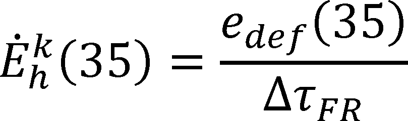
For coil-only system heat pumps, increase Q̇hk(35) by,

and increase Ėhk(35) by,
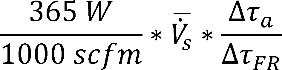
where V̇̅s is the average indoor air volume rate measured during the frost accumulation heating mode test and is expressed in units of cubic feet per minute of standard air (scfm).
c. For heat pumps having a constant-air-volume-rate indoor blower, the five additional steps listed below are required if the average of the external static pressures measured during sub-interval H exceeds the applicable section 3.1.4.4, 3.1.4.5, or 3.1.4.6 minimum (or targeted) external static pressure (ΔPmin) by 0.03 inches of water or more:
(1) Measure the average power consumption of the indoor blower motor (Ėfan,1) and record the corresponding external static pressure (ΔP1) during or immediately following the frost accumulation heating mode test. Make the measurement at a time when the heat pump is heating, except for the first 10 minutes after the termination of a defrost cycle.
(2) After the frost accumulation heating mode test is completed and while maintaining the same test conditions, adjust the exhaust fan of the airflow measuring apparatus until the external static pressure increases to approximately ΔP1 + (ΔP1 − ΔPmin).
(3) After re-establishing steady readings for the fan motor power and external static pressure, determine average values for the indoor blower power (Ėfan,2) and the external static pressure (ΔP2) by making measurements over a 5-minute interval.
(4) Approximate the average power consumption of the indoor blower motor had the frost accumulation heating mode test been conducted at ΔPmin using linear extrapolation:

(5) Decrease the total heating capacity, Q̇hk(35), by the quantity [(Ėfan,1−Ėfan,min) · (Δτa/ΔτFR], when expressed on a Btu/h basis. Decrease the total electrical power, Ehk(35), by the same quantity, now expressed in watts.
3.9.2 Demand Defrost Credit
a. Assign the demand defrost credit, Fdef, that is used in section 4.2 of this appendix to the value of 1 in all cases except for heat pumps having a demand-defrost control system (see section 1.2 of this appendix, Definitions). For such qualifying heat pumps, evaluate Fdef using,

where:
Δτdef = the time between defrost terminations (in hours) or 1.5, whichever is greater. A value of 6 must be assigned to Δτdef if this limit is reached during a frost accumulation test and the heat pump has not completed a defrost cycle.
Δτmax = maximum time between defrosts as allowed by the controls (in hours) or 12, whichever is less, as provided in the certification report.
b. For two-capacity heat pumps and for section 3.6.2 units, evaluate the above equation using the Δτdef that applies based on the frost accumulation test conducted at high capacity and/or at the heating full-load air volume rate. For variable-speed heat pumps, evaluate Δτdef based on the required frost accumulation test conducted at the intermediate compressor speed.
3.10 Test Procedures for Steady-State Low Temperature Heating Mode Tests (the H3, H32, and H31 Tests)
Except for the modifications noted in this section, conduct the low temperature heating mode test using the same approach as specified in section 3.7 of this appendix for the maximum and high temperature tests. After satisfying the section 3.7 requirements for the pretest interval but before beginning to collect data to determine Q̇hk(17) and Ėhk(17), conduct a defrost cycle. This defrost cycle may be manually or automatically initiated. The defrost sequence must be terminated by the action of the heat pump's defrost controls. Begin the 30-minute data collection interval described in section 3.7 of this appendix, from which Q̇hk(17) and Ėhk(17) are determined, no sooner than 10 minutes after defrost termination. Defrosts should be prevented over the 30-minute data collection interval.
3.11 Additional Requirements for the Secondary Test Methodst
3.11.1 If Using the Outdoor Air Enthalpy Method as the Secondary Test Method
a. For all cooling mode and heating mode tests, first conduct a test without the outdoor air-side test apparatus described in section 2.10.1 of this appendix connected to the outdoor unit (“free outdoor air” test).
b. For the first section 3.2 steady-state cooling mode test and the first section 3.6 steady-state heating mode test, conduct a second test in which the outdoor-side apparatus is connected (“ducted outdoor air” test). No other cooling mode or heating mode tests require the ducted outdoor air test so long as the unit operates the outdoor fan during all cooling mode steady-state tests at the same speed and all heating mode steady-state tests at the same speed. If using more than one outdoor fan speed for the cooling mode steady-state tests, however, conduct the ducted outdoor air test for each cooling mode test where a different fan speed is first used. This same requirement applies for the heating mode tests.
3.11.1.1 Free Outdoor Air Test
a. For the free outdoor air test, connect the indoor air-side test apparatus to the indoor coil; do not connect the outdoor air-side test apparatus. Allow the test room reconditioning apparatus and the unit being tested to operate for at least one hour. After attaining equilibrium conditions, measure the following quantities at equal intervals that span 5 minutes or less:
(1) The section 2.10.1 evaporator and condenser temperatures or pressures;
(2) Parameters required according to the indoor air enthalpy method.
Continue these measurements until a 30-minute period (e.g., seven consecutive 5-minute samples) is obtained where the Table 9 or Table 16, whichever applies, test tolerances are satisfied.
b. For cases where a ducted outdoor air test is not required per section 3.11.1.b of this appendix, the free outdoor air test constitutes the “official” test for which validity is not based on comparison with a secondary test.
c. For cases where a ducted outdoor air test is required per section 3.11.1.b of this appendix, the following conditions must be met for the free outdoor air test to constitute a valid “official” test:
(1) Achieve the energy balance specified in section 3.1.1 of this appendix for the ducted outdoor air test (i.e., compare the capacities determined using the indoor air enthalpy method and the outdoor air enthalpy method).
(2) The capacities determined using the indoor air enthalpy method from the ducted outdoor air and free outdoor tests must agree within 2 percent.
3.11.1.2 Ducted Outdoor Air Test
a. The test conditions and tolerances for the ducted outdoor air test are the same as specified for the free outdoor air test described in Section 3.11.1.1 of this appendix.
b. After collecting 30 minutes of steady-state data during the free outdoor air test, connect the outdoor air-side test apparatus to the unit for the ducted outdoor air test. Adjust the exhaust fan of the outdoor airflow measuring apparatus until averages for the evaporator and condenser temperatures, or the saturated temperatures corresponding to the measured pressures, agree within ±0.5 °F of the averages achieved during the free outdoor air test. Collect 30 minutes of steady-state data after re-establishing equilibrium conditions.
c. During the ducted outdoor air test, at intervals of 5 minutes or less, measure the parameters required according to the indoor air enthalpy method and the outdoor air enthalpy method for the prescribed 30 minutes.
d. For cooling mode ducted outdoor air tests, calculate capacity based on outdoor air-enthalpy measurements as specified in sections 7.3.3.2 and 7.3.3.3 of ANSI/ASHRAE 37-2009 (incorporated by reference, see § 430.3). For heating mode ducted tests, calculate heating capacity based on outdoor air-enthalpy measurements as specified in sections 7.3.4.2 and 7.3.3.4.3 of the same ANSI/ASHRAE Standard. Adjust the outdoor-side capacity according to section 7.3.3.4 of ANSI/ASHRAE 37-2009 to account for line losses when testing split systems. As described in section 8.6.2 of ANSI/ASHRAE 37-2009, use the outdoor air volume rate as measured during the ducted outdoor air tests to calculate capacity for checking the agreement with the capacity calculated using the indoor air enthalpy method.
3.11.2 If Using the Compressor Calibration Method as the Secondary Test Method
a. Conduct separate calibration tests using a calorimeter to determine the refrigerant flow rate. Or for cases where the superheat of the refrigerant leaving the evaporator is less than 5 °F, use the calorimeter to measure total capacity rather than refrigerant flow rate. Conduct these calibration tests at the same test conditions as specified for the tests in this appendix. Operate the unit for at least one hour or until obtaining equilibrium conditions before collecting data that will be used in determining the average refrigerant flow rate or total capacity. Sample the data at equal intervals that span 5 minutes or less. Determine average flow rate or average capacity from data sampled over a 30-minute period where the Table 9 (cooling) or the Table 16 (heating) tolerances are satisfied. Otherwise, conduct the calibration tests according to sections 5, 6, 7, and 8 of ASHRAE 23.1-2010 (incorporated by reference, see § 430.3); sections 5, 6, 7, 8, 9, and 11 of ASHRAE 41.9-2011 (incorporated by reference, see § 430.3); and section 7.4 of ANSI/ASHRAE 37-2009 (incorporated by reference, see § 430.3).
b. Calculate space cooling and space heating capacities using the compressor calibration method measurements as specified in section 7.4.5 and 7.4.6 respectively, of ANSI/ASHRAE 37-2009.
3.11.3 If Using the Refrigerant-Enthalpy Method as the Secondary Test Method
Conduct this secondary method according to section 7.5 of ANSI/ASHRAE 37-2009. Calculate space cooling and heating capacities using the refrigerant-enthalpy method measurements as specified in sections 7.5.4 and 7.5.5, respectively, of the same ASHRAE Standard.
3.12 Rounding of Space Conditioning Capacities for Reporting Purposes
a. When reporting rated capacities, round them off as specified in § 430.23 (for a single unit) and in 10 CFR 429.16 (for a sample).
b. For the capacities used to perform the calculations in section 4 of this appendix, however, round only to the nearest integer.
3.13 Laboratory Testing to Determine Off Mode Average Power Ratings
Voltage tolerances: As a percentage of reading, test operating tolerance shall be 2.0 percent and test condition tolerance shall be 1.5 percent (see section 1.2 of this appendix for definitions of these tolerances).
Conduct one of the following tests: If the central air conditioner or heat pump lacks a compressor crankcase heater, perform the test in section 3.13.1 of this appendix; if the central air conditioner or heat pump has a compressor crankcase heater that lacks controls and is not self-regulating, perform the test in section 3.13.1 of this appendix; if the central air conditioner or heat pump has a crankcase heater with a fixed power input controlled with a thermostat that measures ambient temperature and whose sensing element temperature is not affected by the heater, perform the test in section 3.13.1 of this appendix; if the central air conditioner or heat pump has a compressor crankcase heater equipped with self-regulating control or with controls for which the sensing element temperature is affected by the heater, perform the test in section 3.13.2 of this appendix.
3.13.1 This Test Determines the Off Mode Average Power Rating for Central Air Conditioners and Heat Pumps That Lack a Compressor Crankcase Heater, or Have a Compressor Crankcase Heating System That Can Be Tested Without Control of Ambient Temperature During the Test. This Test Has No Ambient Condition Requirements
a. Test Sample Set-up and Power Measurement: For coil-only systems, provide a furnace or modular blower that is compatible with the system to serve as an interface with the thermostat (if used for the test) and to provide low-voltage control circuit power. Make all control circuit connections between the furnace (or modular blower) and the outdoor unit as specified by the manufacturer's installation instructions. Measure power supplied to both the furnace or modular blower and power supplied to the outdoor unit. Alternatively, provide a compatible transformer to supply low-voltage control circuit power, as described in section 2.2.d of this appendix. Measure transformer power, either supplied to the primary winding or supplied by the secondary winding of the transformer, and power supplied to the outdoor unit. For blower coil and single-package systems, make all control circuit connections between components as specified by the manufacturer's installation instructions, and provide power and measure power supplied to all system components.
b. Configure Controls: Configure the controls of the central air conditioner or heat pump so that it operates as if connected to a building thermostat that is set to the OFF position. Use a compatible building thermostat if necessary to achieve this configuration. For a thermostat-controlled crankcase heater with a fixed power input, bypass the crankcase heater thermostat if necessary to energize the heater.
c. Measure P2x: If the unit has a crankcase heater time delay, make sure that time delay function is disabled or wait until delay time has passed. Determine the average power from non-zero value data measured over a 5-minute interval of the non-operating central air conditioner or heat pump and designate the average power as P2x, the heating season total off mode power.
d. Measure Px for coil-only split systems and for blower coil split systems for which a furnace or a modular blower is the designated air mover: Disconnect all low-voltage wiring for the outdoor components and outdoor controls from the low-voltage transformer. Determine the average power from non-zero value data measured over a 5-minute interval of the power supplied to the (remaining) low-voltage components of the central air conditioner or heat pump, or low-voltage power, Px. This power measurement does not include line power supplied to the outdoor unit. It is the line power supplied to the air mover, or, if a compatible transformer is used instead of an air mover, it is the line power supplied to the transformer primary coil. If a compatible transformer is used instead of an air mover and power output of the low-voltage secondary circuit is measured, Px is zero.
e. Calculate P2: Set the number of compressors equal to the unit's number of single-stage compressors plus 1.75 times the unit's number of compressors that are not single-stage.
For single-package systems and blower coil split systems for which the designated air mover is not a furnace or modular blower, divide the heating season total off mode power (P2x) by the number of compressors to calculate P2, the heating season per-compressor off mode power. Round P2 to the nearest watt. The expression for calculating P2 is as follows:
For coil-only split systems and blower coil split systems for which a furnace or a modular blower is the designated air mover, subtract the low-voltage power (Px) from the heating season total off mode power (P2x) and divide by the number of compressors to calculate P2, the heating season per-compressor off mode power. Round P2 to the nearest watt. The expression for calculating P2 is as follows:

f. Shoulder-season per-compressor off mode power, P1: If the system does not have a crankcase heater, has a crankcase heater without controls that is not self-regulating, or has a value for the crankcase heater turn-on temperature (as certified in the DOE Compliance Certification Database) that is higher than 71 °F, P1 is equal to P2.
Otherwise, de-energize the crankcase heater (by removing the thermostat bypass or otherwise disconnecting only the power supply to the crankcase heater) and repeat the measurement as described in section 3.13.1.c of this appendix. Designate the measured average power as P1x, the shoulder season total off mode power.
Determine the number of compressors as described in section 3.13.1.e of this appendix.
For single-package systems and blower coil systems for which the designated air mover is not a furnace or modular blower, divide the shoulder season total off mode power (P1x) by the number of compressors to calculate P1, the shoulder season per-compressor off mode power. Round P1 to the nearest watt. The expression for calculating P1 is as follows:
For coil-only split systems and blower coil split systems for which a furnace or a modular blower is the designated air mover, subtract the low-voltage power (Px) from the shoulder season total off mode power (P1x) and divide by the number of compressors to calculate P1, the shoulder season per-compressor off mode power. Round P1 to the nearest watt. The expression for calculating P1 is as follows:
3.13.2 This Test Determines the Off Mode Average Power Rating for Central Air Conditioners and Heat Pumps for Which Ambient Temperature Can Affect the Measurement of Crankcase Heater Power
a. Test Sample Set-up and Power Measurement: Set up the test and measurement as described in section 3.13.1.a of this appendix.
b. Configure Controls: Position a temperature sensor to measure the outdoor dry-bulb temperature in the air between 2 and 6 inches from the crankcase heater control temperature sensor or, if no such temperature sensor exists, position it in the air between 2 and 6 inches from the crankcase heater. Utilize the temperature measurements from this sensor for this portion of the test procedure. Configure the controls of the central air conditioner or heat pump so that it operates as if connected to a building thermostat that is set to the OFF position. Use a compatible building thermostat if necessary to achieve this configuration.
Conduct the test after completion of the B, B1, or B2 test. Alternatively, start the test when the outdoor dry-bulb temperature is at 82 °F and the temperature of the compressor shell (or temperature of each compressor's shell if there is more than one compressor) is at least 81 °F. Then adjust the outdoor temperature at a rate of change of no more than 20 °F per hour and achieve an outdoor dry-bulb temperature of 72 °F. Maintain this temperature within ±2 °F while making the power measurement, as described in section 3.13.2.c of this appendix.
c. Measure P1x: If the unit has a crankcase heater time delay, make sure that time delay function is disabled or wait until delay time has passed. Determine the average power from non-zero value data measured over a 5-minute interval of the non-operating central air conditioner or heat pump and designate the average power as P1x, the shoulder season total off mode power. For units with crankcase heaters which operate during this part of the test and whose controls cycle or vary crankcase heater power over time, the test period shall consist of three complete crankcase heater cycles or 18 hours, whichever comes first. Designate the average power over the test period as P1x, the shoulder season total off mode power.
d. Reduce outdoor temperature: Approach the target outdoor dry-bulb temperature by adjusting the outdoor temperature at a rate of change of no more than 20 °F per hour. This target temperature is five degrees Fahrenheit less than the temperature specified by the manufacturer in the DOE Compliance Certification Database at which the crankcase heater turns on. Maintain the target temperature within ±2 °F while making the power measurement, as described in section 3.13.2.e of this appendix.
e. Measure P2x: If the unit has a crankcase heater time delay, make sure that time delay function is disabled or wait until delay time has passed. Determine the average non-zero power of the non-operating central air conditioner or heat pump over a 5-minute interval and designate it as P2x, the heating season total off mode power. For units with crankcase heaters whose controls cycle or vary crankcase heater power over time, the test period shall consist of three complete crankcase heater cycles or 18 hours, whichever comes first. Designate the average power over the test period as P2x, the heating season total off mode power.
f. Measure Px for coil-only split systems and for blower coil split systems for which a furnace or modular blower is the designated air mover: Disconnect all low-voltage wiring for the outdoor components and outdoor controls from the low-voltage transformer. Determine the average power from non-zero value data measured over a 5-minute interval of the power supplied to the (remaining) low-voltage components of the central air conditioner or heat pump, or low-voltage power, Px.. This power measurement does not include line power supplied to the outdoor unit. It is the line power supplied to the air mover, or, if a compatible transformer is used instead of an air mover, it is the line power supplied to the transformer primary coil. If a compatible transformer is used instead of an air mover and power output of the low-voltage secondary circuit is measured, Px is zero.
g. Calculate P1:
Set the number of compressors equal to the unit's number of single-stage compressors plus 1.75 times the unit's number of compressors that are not single-stage.
For single-package systems and blower coil split systems for which the air mover is not a furnace or modular blower, divide the shoulder season total off mode power (P1x) by the number of compressors to calculate P1, the shoulder season per-compressor off mode power. Round to the nearest watt. The expression for calculating P1 is as follows:

For coil-only split systems and blower coil split systems for which a furnace or a modular blower is the designated air mover, subtract the low-voltage power (Px) from the shoulder season total off mode power (P1x) and divide by the number of compressors to calculate P1, the shoulder season per-compressor off mode power. Round to the nearest watt. The expression for calculating P1 is as follows:
h. Calculate P2:
Determine the number of compressors as described in section 3.13.2.g of this appendix.
For single-package systems and blower coil split systems for which the air mover is not a furnace, divide the heating season total off mode power (P2x) by the number of compressors to calculate P2, the heating season per-compressor off mode power. Round to the nearest watt. The expression for calculating P2 is as follows:

For coil-only split systems and blower coil split systems for which a furnace or a modular blower is the designated air mover, subtract the low-voltage power (Px) from the heating season total off mode power (P2x) and divide by the number of compressors to calculate P2, the heating season per-compressor off mode power. Round to the nearest watt. The expression for calculating P2 is as follows:
4. Calculations of Seasonal Performance Descriptors
4.1 Seasonal Energy Efficiency Ratio (SEER) Calculations. SEER must be calculated as follows: For equipment covered under sections 4.1.2, 4.1.3, and 4.1.4 of this appendix, evaluate the seasonal energy efficiency ratio,
where:

Tj = the outdoor bin temperature, °F. Outdoor temperatures are grouped or “binned.” Use bins of 5 °F with the 8 cooling season bin temperatures being 67, 72, 77, 82, 87, 92, 97, and 102 °F.
j = the bin number. For cooling season calculations, j ranges from 1 to 8.
Additionally, for sections 4.1.2, 4.1.3, and 4.1.4 of this appendix, use a building cooling load, BL(Tj). When referenced, evaluate BL(Tj) for cooling using,

where:
Q̇ck=2(95) = the space cooling capacity determined from the A2 test and calculated as specified in section 3.3 of this appendix, Btu/h.
1.1 = sizing factor, dimensionless.
The temperatures 95 °F and 65 °F in the building load equation represent the selected outdoor design temperature and the zero-load base temperature, respectively.
4.1.1 SEER Calculations for a Blower Coil System Having a Single-Speed Compressor and Either a Fixed-Speed Indoor Blower or a Constant-Air-Volume-Rate Indoor Blower, or a Coil-Only System Air Conditioner or Heat Pump
a. Evaluate the seasonal energy efficiency ratio, expressed in units of Btu/watt-hour, using:
SEER = PLF(0.5) * EERB
where:

PLF(0.5) = 1 − 0.5 · CDc, the part-load performance factor evaluated at a cooling load factor of 0.5, dimensionless.
b. Refer to section 3.3 of this appendix regarding the definition and calculation of Q̇c(82) and Ėc(82). Evaluate the cooling mode cyclic degradation factor CDc as specified in section 3.5.3 of this appendix.
4.1.2 SEER Calculations for an Air Conditioner or Heat Pump Having a Single-Speed Compressor and a Variable-Speed Variable-Air-Volume-Rate Indoor Blower
4.1.2.1 Units Covered by Section 3.2.2.1 of This Appendix Where Indoor Blower Capacity Modulation Correlates With the Outdoor Dry Bulb Temperature
The manufacturer must provide information on how the indoor air volume rate or the indoor blower speed varies over the outdoor temperature range of 67 °F to 102 °F. Calculate SEER using Equation 4.1-1. Evaluate the quantity qc(Tj)/N in Equation 4.1-1 using,

where:
Q̇c(Tj) = the space cooling capacity of the test unit when operating at outdoor temperature, Tj, Btu/h.
nj/N = fractional bin hours for the cooling season; the ratio of the number of hours during the cooling season when the outdoor temperature fell within the range represented by bin temperature Tj to the total number of hours in the cooling season, dimensionless.
a. For the space cooling season, assign nj/N as specified in Table 19. Use Equation 4.1-2 to calculate the building load, BL(Tj). Evaluate Q̇c(Tj) using,

where:

the space cooling capacity of the test unit at outdoor temperature Tj if operated at the cooling minimum air volume rate, Btu/h.

the space cooling capacity of the test unit at outdoor temperature Tj if operated at the Cooling full-load air volume rate, Btu/h.
b. For units where indoor blower speed is the primary control variable, FPck=1 denotes the fan speed used during the required A1 and B1 tests (see section 3.2.2.1 of this appendix), FPck=2 denotes the fan speed used during the required A2 and B2 tests, and FPc(Tj) denotes the fan speed used by the unit when the outdoor temperature equals Tj. For units where indoor air volume rate is the primary control variable, the three FPc's are similarly defined only now being expressed in terms of air volume rates rather than fan speeds. Refer to sections 3.2.2.1, 3.1.4 to 3.1.4.2, and 3.3 of this appendix regarding the definitions and calculations of Q̇ck=1(82), Q̇ck=1(95), Q̇ck=2(82), and Q̇ck=2(95).

where:
PLFj = 1 − CDc · [1 − X(Tj)], the part load factor, dimensionless.
Ėc(Tj) = the electrical power consumption of the test unit when operating at outdoor temperature Tj, W.
c. The quantities X(Tj) and nj/N are the same quantities as used in Equation 4.1.2-1. Evaluate the cooling mode cyclic degradation factor CDc as specified in section 3.5.3 of this appendix.
d. Evaluate Ėc(Tj) using,
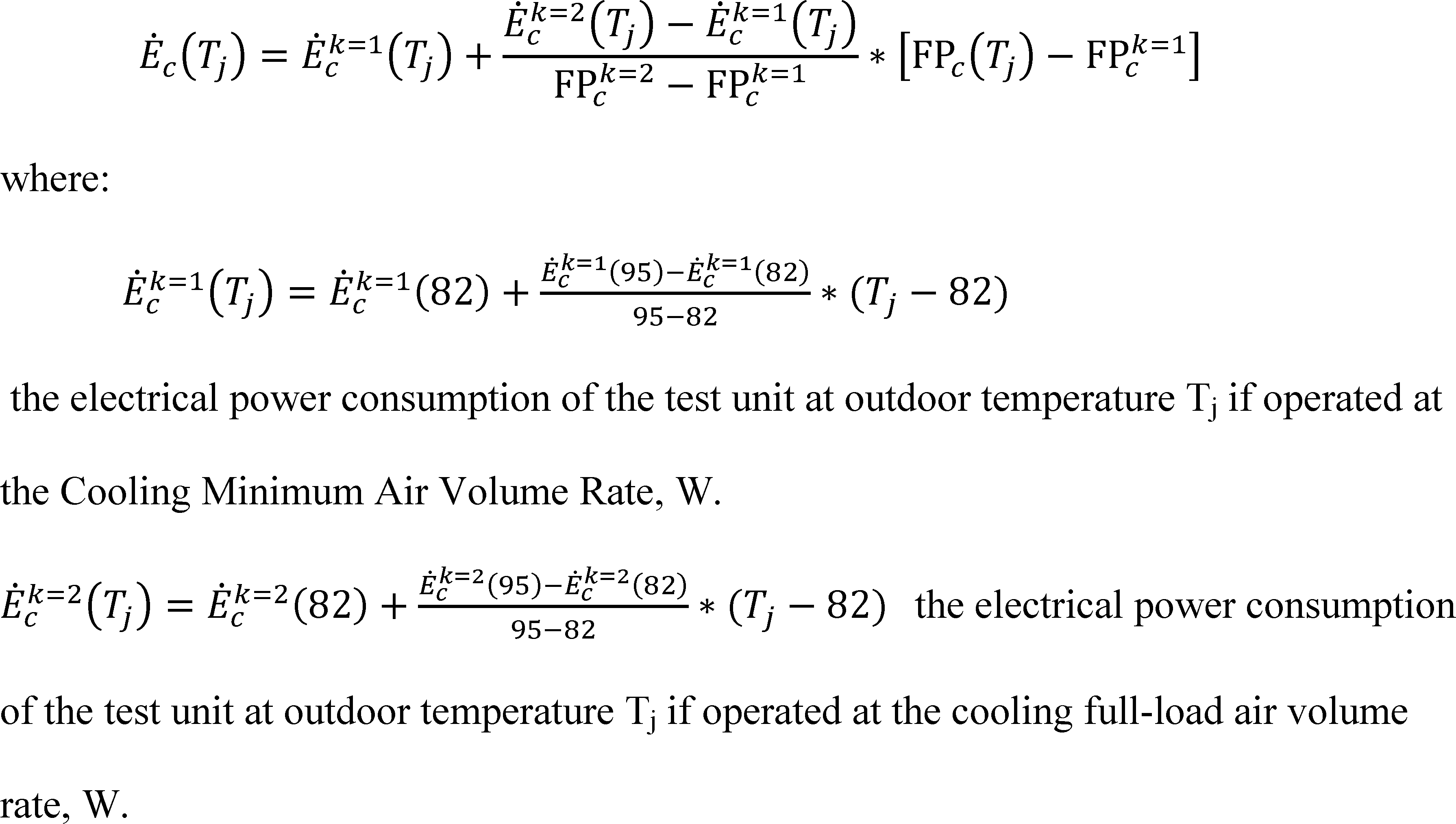
e. The parameters FPck=1, and FPck=2, and FPc(Tj) are the same quantities that are used when evaluating Equation 4.1.2-2. Refer to sections 3.2.2.1, 3.1.4 to 3.1.4.2, and 3.3 of this appendix regarding the definitions and calculations of Ėck=1(82), Ėck=1(95), Ėck=2(82), and Ėck=2(95).
4.1.2.2 Units Covered by Section 3.2.2.2 of This Appendix Where Indoor Blower Capacity Modulation Is Used To Adjust the Sensible to Total Cooling Capacity Ratio. Calculate SEER as specified in section 4.1.1 of this appendix.
4.1.3 SEER Calculations for an Air Conditioner or Heat Pump Having a Two-Capacity Compressor
Calculate SEER using Equation 4.1-1. Evaluate the space cooling capacity, Q̇ck=1 (Tj), and electrical power consumption, Ėck=1 (Tj), of the test unit when operating at low compressor capacity and outdoor temperature Tj using,


where Q̇ck=1 (82) and Ėck=1 (82) are determined from the B1 test, Q̇ck=1 (67) and Ėck=1 (67) are determined from the F1 test, and all four quantities are calculated as specified in section 3.3 of this appendix. Evaluate the space cooling capacity, Q̇ck=2 (Tj), and electrical power consumption, Ėck=2 (Tj), of the test unit when operating at high compressor capacity and outdoor temperature Tj using,


where Q̇ck=2(95) and Ėck=2(95) are determined from the A2 test, Q̇ck=2(82), and Ėck=2(82), are determined from the B2test, and all are calculated as specified in section 3.3 of this appendix.
The calculation of Equation 4.1-1 quantities qc(Tj)/N and ec(Tj)/N differs depending on whether the test unit would operate at low capacity (section 4.1.3.1 of this appendix), cycle between low and high capacity (section 4.1.3.2 of this appendix), or operate at high capacity (sections 4.1.3.3 and 4.1.3.4 of this appendix) in responding to the building load. For units that lock out low capacity operation at higher outdoor temperatures, the outdoor temperature at which the unit locks out must be that specified by the manufacturer in the certification report so that the appropriate equations are used. Use Equation 4.1-2 to calculate the building load, BL(Tj), for each temperature bin.
4.1.3.1 Steady-State Space Cooling Capacity at Low Compressor Capacity Is Greater Than or Equal to the Building Cooling Load at Temperature Tj, Q̇ck=1(Tj) ≥BL(Tj)

where:
Xk=1(Tj) = BL(Tj)/Q̇ck=1(Tj), the cooling mode low capacity load factor for temperature bin j, dimensionless.
PLFj = 1 − CDc · [1 − Xk=1(Tj)], the part load factor, dimensionless.
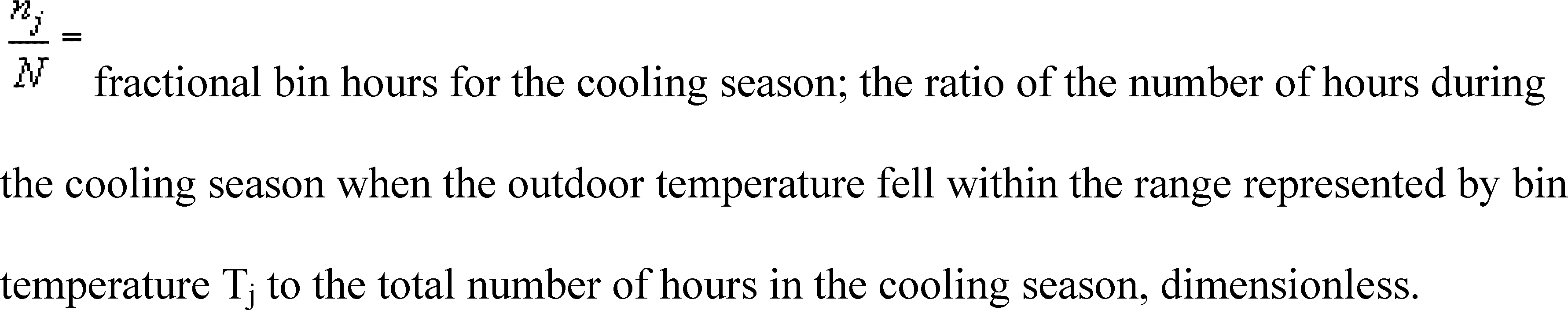
Obtain the fractional bin hours for the cooling season, nj/N, from Table 19. Use Equations 4.1.3-1 and 4.1.3-2, respectively, to evaluate Q̇ck=1(Tj) and Ėck=1(Tj). Evaluate the cooling mode cyclic degradation factor CDc as specified in section 3.5.3 of this appendix.
Table 19 - Distribution of Fractional Hours Within Cooling Season Temperature Bins
| Bin number,
j | Bin
temperature range °F | Representative temperature for bin
°F | Fraction of of total
temperature bin hours, nj/N |
|---|---|---|---|
| 1 | 65-69 | 67 | 0.214 |
| 2 | 70-74 | 72 | 0.231 |
| 3 | 75-79 | 77 | 0.216 |
| 4 | 80-84 | 82 | 0.161 |
| 5 | 85-89 | 87 | 0.104 |
| 6 | 90-94 | 92 | 0.052 |
| 7 | 95-99 | 97 | 0.018 |
| 8 | 100-104 | 102 | 0.004 |
4.1.3.2 Unit Alternates Between High (k=2) and Low (k=1) Compressor Capacity To Satisfy the Building Cooling Load at Temperature Tj, Q̇ck=1(Tj) BL(Tj) Q̇ck=2(Tj)

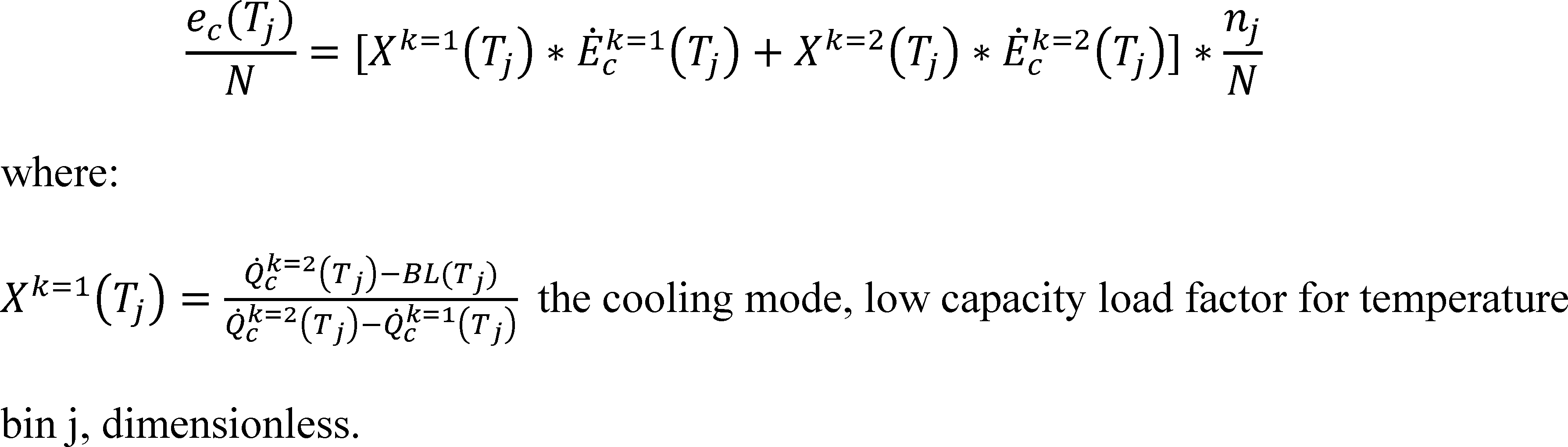
Xk=2(Tj) = 1 − Xk=1(Tj), the cooling mode, high capacity load factor for temperature bin j, dimensionless.
Obtain the fractional bin hours for the cooling season, nj/N, from Table 19. Use Equations 4.1.3-1 and 4.1.3-2, respectively, to evaluate Q̇ck=1(Tj) and Ėck=1(Tj). Use Equations 4.1.3-3 and 4.1.3-4, respectively, to evaluate Q̇ck=2(Tj) and Ėck=2(Tj).
4.1.3.3 Unit Only Operates at High (k=2) Compressor Capacity at Temperature Tj and Its Capacity Is Greater Than the Building Cooling Load, BL(Tj) Q̇ck=2(Tj). This section applies to units that lock out low compressor capacity operation at higher outdoor temperatures.

where:
Xk=2(Tj) = BL(Tj)/Q̇ck=2(Tj), the cooling mode high capacity load factor for temperature bin j, dimensionless.
PLFj = 1 − CDc(k = 2) * [1 − Xk=2(Tj) the part load factor, dimensionless.

4.1.3.4 Unit Must Operate Continuously at High (k=2) Compressor Capacity at Temperature Tj, BL(Tj) ≥Q̇ck=2(Tj)

Obtain the fractional bin hours for the cooling season, nj/N, from Table 19. Use Equations 4.1.3-3 and 4.1.3-4, respectively, to evaluate Q̇ck=2(Tj) and Ėck=2(Tj).
4.1.4 SEER Calculations for an Air Conditioner or Heat Pump Having a Variable-Speed Compressor
Calculate SEER using Equation 4.1-1. Evaluate the space cooling capacity, Q̇ck=1(Tj), and electrical power consumption, Ėck=1(Tj), of the test unit when operating at minimum compressor speed and outdoor temperature Tj. Use,


where Q̇ck=1(82) and Ėck=1(82) are determined from the B1 test, Q̇ck=1(67) and Ėck=1(67) are determined from the F1 test, and all four quantities are calculated as specified in section 3.3 of this appendix.
Evaluate the space cooling capacity, Q̇ck=2(Tj), and electrical power consumption, Ėck=2(Tj), of the test unit when operating at full compressor speed and outdoor temperature Tj. Use Equations 4.1.3-3 and 4.1.3-4, respectively, where Q̇ck=2(95) and Ėck=2(95) are determined from the A2 test, Q̇ck=2(82) and Ėck=2(82) are determined from the B2 test, and all four quantities are calculated as specified in section 3.3 of this appendix. Calculate the space cooling capacity, Q̇ck=v(Tj), and electrical power consumption, Ėck=v(Tj), of the test unit when operating at outdoor temperature Tj and the intermediate compressor speed used during the section 3.2.4 (and Table 8) EV test of this appendix using,


where Q̇ck=v(87) and Ėck=v(87) are determined from the EV test and calculated as specified in section 3.3 of this appendix. Approximate the slopes of the k=v intermediate speed cooling capacity and electrical power input curves, MQ and ME, as follows:

Use Equations 4.1.4-1 and 4.1.4-2, respectively, to calculate Q̇ck=1(87) and Ėck=1(87).
4.1.4.1 Steady-State Space Cooling Capacity When Operating at Minimum Compressor Speed Is Greater Than or Equal to the Building Cooling Load at Temperature Tj, Q̇ck=1(Tj) ≥BL(Tj)

where:
Xk=1(Tj) = BL(Tj)/Q̇ck=1(Tj), the cooling mode minimum speed load factor for temperature bin j, dimensionless.
PLFj = 1 − CDc · [1 − Xk=1(Tj)], the part load factor, dimensionless.
nj/N = fractional bin hours for the cooling season; the ratio of the number of hours during the cooling season when the outdoor temperature fell within the range represented by bin temperature Tj to the total number of hours in the cooling season, dimensionless.
Obtain the fractional bin hours for the cooling season, nj/N, from Table 19. Use Equations 4.1.3-1 and 4.1.3-2, respectively, to evaluate Q̇ck=l (Tj) and Ėck=l (Tj). Evaluate the cooling mode cyclic degradation factor CDc as specified in section 3.5.3 of this appendix.
4.1.4.2 Unit Operates at an Intermediate Compressor Speed (k=i) In Order To Match the Building Cooling Load at Temperature Tj,Q̇ck=1(Tj) BL(Tj) Q̇ck=2(Tj)

where:
Q̇ck=i(Tj) = BL(Tj), the space cooling capacity delivered by the unit in matching the building load at temperature Tj, Btu/h. The matching occurs with the unit operating at compressor speed k = i.

EERk=i(Tj) = the steady-state energy efficiency ratio of the test unit when operating at a compressor speed of k = i and temperature Tj, Btu/h per W.
Obtain the fractional bin hours for the cooling season, nj/N, from Table 19. For each temperature bin where the unit operates at an intermediate compressor speed, determine the energy efficiency ratio EERk=i(Tj) using,
EERk=i(Tj) = A + B · Tj + C · Tj2.
For each unit, determine the coefficients A, B, and C by conducting the following calculations once:

where:
T1 = the outdoor temperature at which the unit, when operating at minimum compressor speed, provides a space cooling capacity that is equal to the building load (Q̇ck=l(Tl) = BL(T1)), °F. Determine T1 by equating Equations 4.1.3-1 and 4.1-2 and solving for outdoor temperature.
Tv = the outdoor temperature at which the unit, when operating at the intermediate compressor speed used during the section 3.2.4 EV test of this appendix, provides a space cooling capacity that is equal to the building load (Q̇ck=v(Tv) = BL(Tv)), °F. Determine Tv by equating Equations 4.1.4-3 and 4.1-2 and solving for outdoor temperature.
T2 = the outdoor temperature at which the unit, when operating at full compressor speed, provides a space cooling capacity that is equal to the building load (Q̇ck=2(T2) = BL(T2)), °F. Determine T2 by equating Equations 4.1.3-3 and 4.1-2 and solving for outdoor temperature.

4.1.4.3 Unit Must Operate Continuously at Full (k=2) Compressor Speed at Temperature Tj, BL(Tj) ≥Q̇ck=2(Tj). Evaluate the Equation 4.1-1 Quantities

as specified in section 4.1.3.4 of this appendix with the understanding that Q̇ck=2(Tj) and Ėck=2(Tj) correspond to full compressor speed operation and are derived from the results of the tests specified in section 3.2.4 of this appendix.
4.1.5 SEER Calculations for an Air Conditioner or Heat Pump Having a Single Indoor Unit With Multiple Indoor Blowers
Calculate SEER using Eq. 4.1-1, where qc(Tj)/N and ec(Tj)/N are evaluated as specified in the applicable subsection.
4.1.5.1 For Multiple Indoor Blower Systems That Are Connected to a Single, Single-Speed Outdoor Unit
a. Calculate the space cooling capacity, Q̇ck=1(Tj), and electrical power consumption, Ėck=1(Tj), of the test unit when operating at the cooling minimum air volume rate and outdoor temperature Tj using the equations given in section 4.1.2.1 of this appendix. Calculate the space cooling capacity, Q̇ck=2(Tj), and electrical power consumption, Ėck=2(Tj), of the test unit when operating at the cooling full-load air volume rate and outdoor temperature Tj using the equations given in section 4.1.2.1 of this appendix. In evaluating the section 4.1.2.1 equations, determine the quantities Q̇ck=1(82) and Ėck=1(82) from the B1 test, Q̇ck=1(95) and Ėck=1(95) from the Al test, Q̇ck=2(82) and Ėck=2(82) from the B2 test, andQ̇ck=2(95) and Ėck=2(95) from the A2 test. Evaluate all eight quantities as specified in section 3.3 of this appendix. Refer to section 3.2.2.1 and Table 6 of this appendix for additional information on the four referenced laboratory tests.
b. Determine the cooling mode cyclic degradation coefficient, CDc, as per sections 3.2.2.1 and 3.5 to 3.5.3 of this appendix. Assign this same value to CDc(K=2).
c. Except for using the above values of Q̇ck=1(Tj), Ėck=1(Tj), Ėck=2(Tj), Q̇ck=2(Tj), CDc, and CDc (K=2), calculate the quantities qc(Tj)/N and ec(Tj)/N as specified in section 4.1.3.1 of this appendix for cases where Q̇ck=1(Tj) ≥BL(Tj). For all other outdoor bin temperatures, Tj, calculate qc(Tj)/N and ec(Tj)/N as specified in section 4.1.3.3 of this appendix if Q̇ck=2(Tj) >BL (Tj) or as specified in section 4.1.3.4 of this appendix if Q̇ck=2(Tj) ≤BL(Tj).
4.1.5.2 Unit Operates at an Intermediate Compressor Speed (k=i) In Order To Match the Building Cooling Load at Temperature Tj,Q̇ck=1(Tj) <BL(Tj) <Q̇ck=2(Tj)

where,
Q̇ck=i(Tj) = BL(Tj), the space cooling capacity delivered by the unit in matching the building load at temperature Tj, Btu/h. The matching occurs with the unit operating at compressor speed k = i.

EERk=i(Tj), the steady-state energy efficiency ratio of the test unit when operating at a compressor speed of k = i and temperature Tj, Btu/h per W.
Obtain the fractional bin hours for the cooling season, nj/N, from Table 19. For each temperature bin where the unit operates at an intermediate compressor speed, determine the energy efficiency ratio EERk=i(Tj) using the following equations,
For each temperature bin where Q̇ck=1(Tj) <BL(Tj) <Q̇ck=v(Tj),

For each temperature bin where Q̇ck=v(Tj) ≤BL(Tj) <Q̇ck=2(Tj),

Where:
EERk=1(Tj) is the steady-state energy efficiency ratio of the test unit when operating at minimum compressor speed and temperature Tj, Btu/h per W, calculated using capacity Q̇ck=1(Tj) calculated using Equation 4.1.4-1 and electrical power consumption Ėck=1(Tj) calculated using Equation 4.1.4-2;
EERk=v(Tj) is the steady-state energy efficiency ratio of the test unit when operating at intermediate compressor speed and temperature Tj, Btu/h per W, calculated using capacity Q̇ck=v(Tj) calculated using Equation 4.1.4-3 and electrical power consumption Ėck=v(Tj) calculated using Equation 4.1.4-4;
EERk=2(Tj) is the steady-state energy efficiency ratio of the test unit when operating at full compressor speed and temperature Tj, Btu/h per W, calculated using capacity Q̇ck=2(Tj) and electrical power consumption Ėck=2(Tj), both calculated as described in section 4.1.4; and
BL(Tj) is the building cooling load at temperature Tj, Btu/h.
4.2 Heating Seasonal Performance Factor (HSPF) Calculations
Unless an approved alternative efficiency determination method is used, as set forth in 10 CFR 429.70(e), HSPF must be calculated as follows: Six generalized climatic regions are depicted in Figure 1 and otherwise defined in Table 20. For each of these regions and for each applicable standardized design heating requirement, evaluate the heating seasonal performance factor using,

where:
e2(Tj)/N = The ratio of the electrical energy consumed by the heat pump during periods of the space heating season when the outdoor temperature fell within the range represented by bin temperature Tj to the total number of hours in the heating season (N), W. For heat pumps having a heat comfort controller, this ratio may also include electrical energy used by resistive elements to maintain a minimum air delivery temperature (see 4.2.5).
RH(Tj)/N = The ratio of the electrical energy used for resistive space heating during periods when the outdoor temperature fell within the range represented by bin temperature Tj to the total number of hours in the heating season (N), W. Except as noted in section 4.2.5 of this appendix, resistive space heating is modeled as being used to meet that portion of the building load that the heat pump does not meet because of insufficient capacity or because the heat pump automatically turns off at the lowest outdoor temperatures. For heat pumps having a heat comfort controller, all or part of the electrical energy used by resistive heaters at a particular bin temperature may be reflected in eh(Tj)/N (see section 4.2.5 of this appendix).
Tj = the outdoor bin temperature, °F. Outdoor temperatures are “binned” such that calculations are only performed based one temperature within the bin. Bins of 5 °F are used.
nj/N= Fractional bin hours for the heating season; the ratio of the number of hours during the heating season when the outdoor temperature fell within the range represented by bin temperature Tj to the total number of hours in the heating season, dimensionless. Obtain nj/N values from Table 20.
j = the bin number, dimensionless.
J = for each generalized climatic region, the total number of temperature bins, dimensionless. Referring to Table 20, J is the highest bin number (j) having a nonzero entry for the fractional bin hours for the generalized climatic region of interest.
Fdef = the demand defrost credit described in section 3.9.2 of this appendix, dimensionless.
BL(Tj) = the building space conditioning load corresponding to an outdoor temperature of Tj; the heating season building load also depends on the generalized climatic region's outdoor design temperature and the design heating requirement, Btu/h.
Table 20 - Generalized Climatic Region Information
| Region No. | ||||||
|---|---|---|---|---|---|---|
| I | II | III | IV | V | VI | |
| Heating Load Hours, HLH | 750 | 1,250 | 1,750 | 2,250 | 2,750 | *2,750 |
| Outdoor Design Temperature, TOD | 37 | 27 | 17 | 5 | −10 | 30 |
| j Tj ( °F) | Fractional Bin Hours, nj/N | |||||
| 1 62 | .291 | .215 | .153 | .132 | .106 | .113 |
| 2 57 | .239 | .189 | .142 | .111 | .092 | .206 |
| 3 52 | .194 | .163 | .138 | .103 | .086 | .215 |
| 4 47 | .129 | .143 | .137 | .093 | .076 | .204 |
| 5 42 | .081 | .112 | .135 | .100 | .078 | .141 |
| 6 37 | .041 | .088 | .118 | .109 | .087 | .076 |
| 7 32 | .019 | .056 | .092 | .126 | .102 | .034 |
| 8 27 | .005 | .024 | .047 | .087 | .094 | .008 |
| 9 22 | .001 | .008 | .021 | .055 | .074 | .003 |
| 10 17 | 0 | .002 | .009 | .036 | .055 | 0 |
| 11 12 | 0 | 0 | .005 | .026 | .047 | 0 |
| 12 7 | 0 | 0 | .002 | .013 | .038 | 0 |
| 13 2 | 0 | 0 | .001 | .006 | .029 | 0 |
| 14 −3 | 0 | 0 | 0 | .002 | .018 | 0 |
| 15 −8 | 0 | 0 | 0 | .001 | .010 | 0 |
| 16 −13 | 0 | 0 | 0 | 0 | .005 | 0 |
| 17 −18 | 0 | 0 | 0 | 0 | .002 | 0 |
| 18 −23 | 0 | 0 | 0 | 0 | .001 | 0 |
Evaluate the building heating load using

Where:
TOD = the outdoor design temperature, °F. An outdoor design temperature is specified for each generalized climatic region in Table 20.
C = 0.77, a correction factor which tends to improve the agreement between calculated and measured building loads, dimensionless.
DHR = the design heating requirement (see section 1.2 of this appendix, Definitions), Btu/h.
Calculate the minimum and maximum design heating requirements for each generalized climatic region as follows:
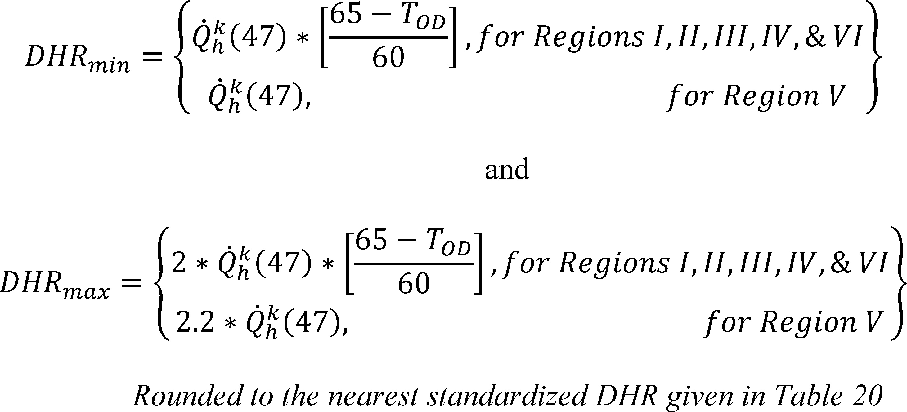
where Q̇hk(47) is expressed in units of Btu/h and otherwise defined as follows:
a. For a single-speed heat pump tested as per section 3.6.1 of this appendix, Q̇hk(47) = Q̇h(47), the space heating capacity determined from the H1 test.
b. For a section 3.6.2 single-speed heat pump or a two-capacity heat pump not covered by item d, Q̇hk(47) = Q̇hk=2(47), the space heating capacity determined from the H1 or H12 test.
c. For a variable-speed heat pump, Q̇hk(47) = Q̇hk=N(47), the space heating capacity determined from the H1N test.
d. For two-capacity, northern heat pumps (see section 1.2 of this appendix, Definitions), Q̇kh(47) = Q̇k=1h(47), the space heating capacity determined from the H11 test.
For all heat pumps, HSPF accounts for the heating delivered and the energy consumed by auxiliary resistive elements when operating below the balance point. This condition occurs when the building load exceeds the space heating capacity of the heat pump condenser. For HSPF calculations for all heat pumps, see either section 4.2.1, 4.2.2, 4.2.3, or 4.2.4 of this appendix, whichever applies.
For heat pumps with heat comfort controllers (see section 1.2 of this appendix, Definitions), HSPF also accounts for resistive heating contributed when operating above the heat-pump-plus-comfort-controller balance point as a result of maintaining a minimum supply temperature. For heat pumps having a heat comfort controller, see section 4.2.5 of this appendix for the additional steps required for calculating the HSPF.
Table 21 - Standardized Design Heating Requirements
[Btu/h]
| 5,000 |
| 10,000 |
| 15,000 |
| 20,000 |
| 25,000 |
| 30,000 |
| 35,000 |
| 40,000 |
| 50,000 |
| 60,000 |
| 70,000 |
| 80,000 |
| 90,000 |
| 100,000 |
| 110,000 |
| 130,000 |
4.2.1 Additional Steps for Calculating the HSPF of a Blower Coil System Heat Pump Having a Single-Speed Compressor and Either a Fixed-Speed Indoor Blower or a Constant-Air-Volume-Rate Indoor Blower Installed, or a Coil-Only System Heat Pump
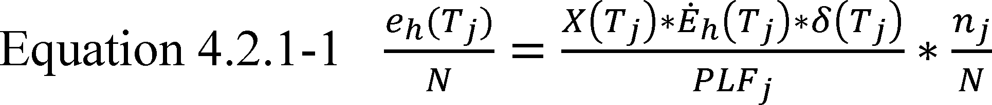
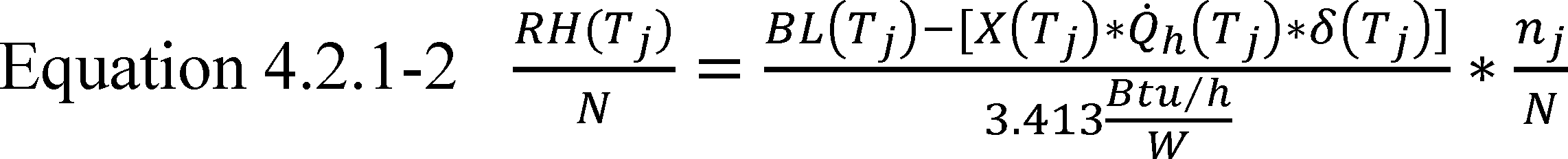
Where:
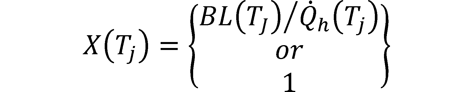
whichever is less; the heating mode load factor for temperature bin j, dimensionless.
Q̇h(Tj) = the space heating capacity of the heat pump when operating at outdoor temperature Tj, Btu/h.
Ėh(Tj) = the electrical power consumption of the heat pump when operating at outdoor temperature Tj, W.
δ(Tj) = the heat pump low temperature cut-out factor, dimensionless.
PLFj = 1 − ĊDh · [1 −X(Tj)] the part load factor, dimensionless.
Use Equation 4.2-2 to determine BL(Tj). Obtain fractional bin hours for the heating season, nj/N, from Table 20. Evaluate the heating mode cyclic degradation factor ĊDh as specified in section 3.8.1 of this appendix.
Determine the low temperature cut-out factor using
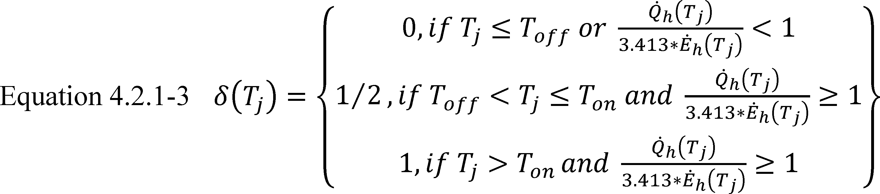
Where:
Toff = the outdoor temperature when the compressor is automatically shut off, °F. (If no such temperature exists, Tj is always greater than Toff and Ton).
Ton = the outdoor temperature when the compressor is automatically turned back on, if applicable, following an automatic shut-off, °F.
Calculate Q̇h(Tj) and Ėh(Tj) using,
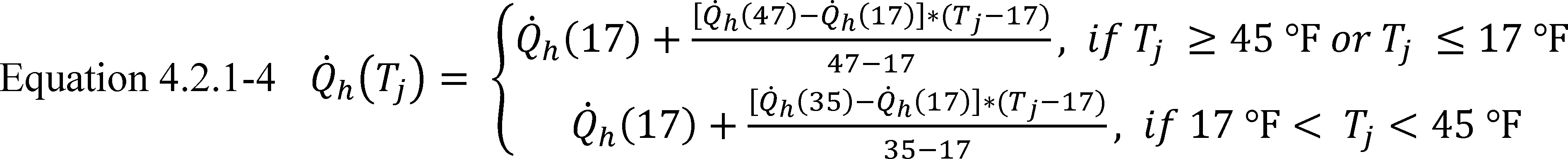
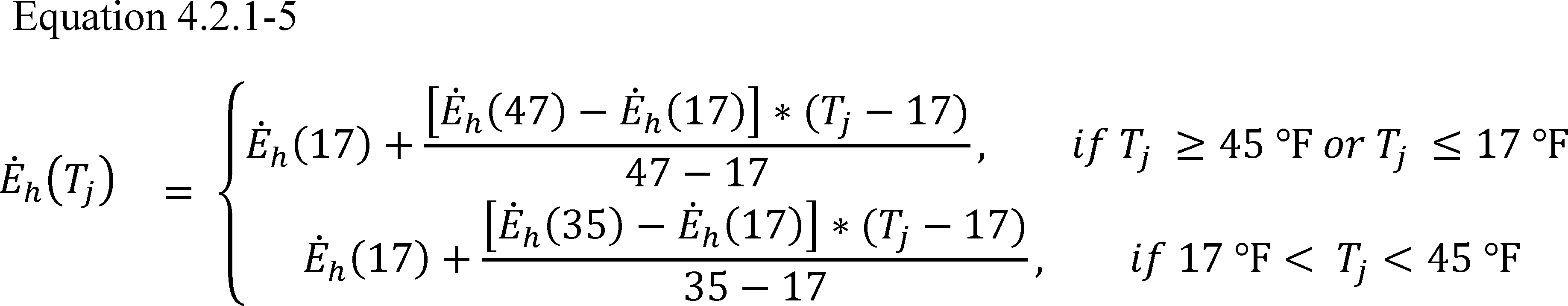
where Q̇h(47) and Ėh(47) are determined from the H1 test and calculated as specified in section 3.7 of this appendix; Q̇h(35) and Ėh(35) are determined from the H2 test and calculated as specified in section 3.9.1 of this appendix; and Q̇h(17) and Ėh(17) are determined from the H3 test and calculated as specified in section 3.10 of this appendix.
4.2.2 Additional Steps for Calculating the HSPF of a Heat Pump Having a Single-Speed Compressor and a Variable-Speed, Variable-Air-Volume-Rate Indoor Blower
The manufacturer must provide information about how the indoor air volume rate or the indoor blower speed varies over the outdoor temperature range of 65 °F to −23 °F. Calculate the quantities

in Equation 4.2-1 as specified in section 4.2.1 of this appendix with the exception of replacing references to the H1C test and section 3.6.1 of this appendix with the H1C1 test and section 3.6.2 of this appendix. In addition, evaluate the space heating capacity and electrical power consumption of the heat pump Q̇h(Tj) and Ėh(Tj) using


where the space heating capacity and electrical power consumption at both low capacity (k=1) and high capacity (k=2) at outdoor temperature Tj are determined using
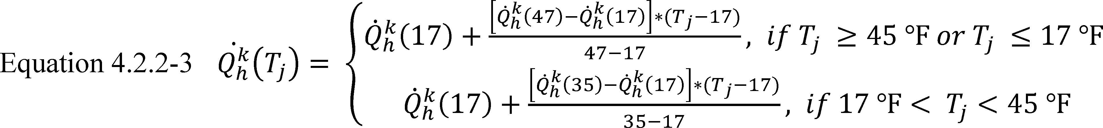

For units where indoor blower speed is the primary control variable, FPhk=1 denotes the fan speed used during the required H11 and H31 tests (see Table 12), FPhk=2 denotes the fan speed used during the required H12, H22, and H32 tests, and FPh(Tj) denotes the fan speed used by the unit when the outdoor temperature equals Tj. For units where indoor air volume rate is the primary control variable, the three FPh's are similarly defined only now being expressed in terms of air volume rates rather than fan speeds. Determine Q̇hk=1(47) and Ėhk=1(47) from the H11 test, and Q̇hk=2(47) and Ėhk=2(47) from the H12 test. Calculate all four quantities as specified in section 3.7 of this appendix. Determine Q̇hk=1(35) and Ėhk=1(35) as specified in section 3.6.2 of this appendix; determine Q̇hk=2(35) and Ėhk=2(35) and from the H22 test and the calculation specified in section 3.9 of this appendix. Determine Q̇hk=1(17) and Ėhk=1(17) from the H31 test, and Q̇hk=2(17) and Ėhk=2(17) from the H32 test. Calculate all four quantities as specified in section 3.10 of this appendix.
4.2.3 Additional Steps for Calculating the HSPF of a Heat Pump Having a Two-Capacity Compressor
The calculation of the Equation 4.2-1 quantities differ depending upon whether the heat pump would operate at low capacity (section 4.2.3.1 of this appendix), cycle between low and high capacity (section 4.2.3.2 of this appendix), or operate at high capacity (sections 4.2.3.3 and 4.2.3.4 of this appendix) in responding to the building load. For heat pumps that lock out low capacity operation at low outdoor temperatures, the outdoor temperature at which the unit locks out must be that specified by the manufacturer in the certification report so that the appropriate equations can be selected.

a. Evaluate the space heating capacity and electrical power consumption of the heat pump when operating at low compressor capacity and outdoor temperature Tj using
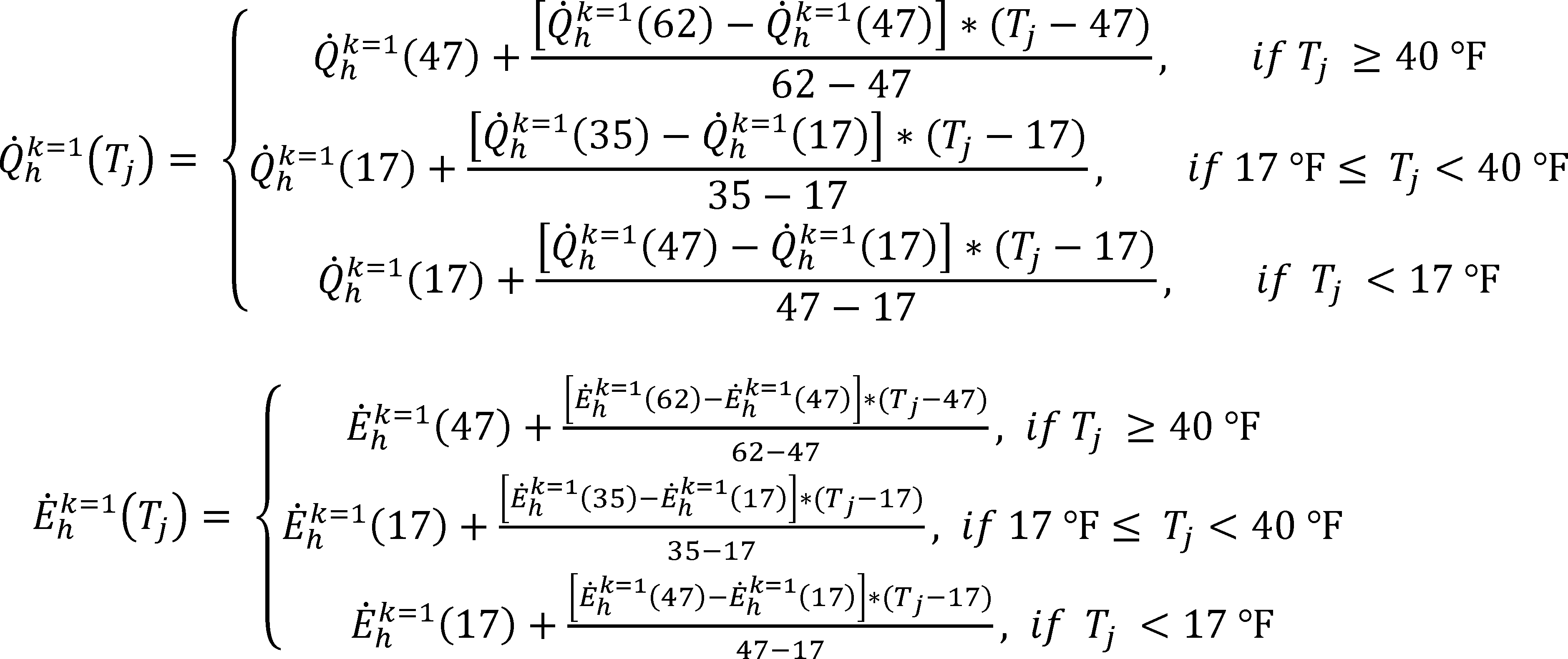
b. Evaluate the space heating capacity and electrical power consumption (Q̇hk=2(Tj) and Ėhk=2 (Tj)) of the heat pump when operating at high compressor capacity and outdoor temperature Tj by solving Equations 4.2.2-3 and 4.2.2-4, respectively, for k=2. Determine Q̇hk=1(62) and Ėhk=1(62) from the H01 test, Q̇hk=1(47) and Ėhk=1(47) from the H11 test, and Q̇hk=2(47) and Ėhk=2(47) from the H12 test. Calculate all six quantities as specified in section 3.7 of this appendix. Determine Q̇hk=2(35) and Ėhk=2(35) from the H22 test and, if required as described in section 3.6.3 of this appendix, determine Q̇hk=1(35) and Ėhk=1(35) from the H21 test. Calculate the required 35 °F quantities as specified in section 3.9 of this appendix. Determine Q̇hk=2(17) and Ėhk=2(17) from the H32 test and, if required as described in section 3.6.3 of this appendix, determine Q̇hk=1(17) and Ėhk=1(17) from the H31 test. Calculate the required 17 °F quantities as specified in section 3.10 of this appendix.
4.2.3.1 Steady-State Space Heating Capacity When Operating at Low Compressor Capacity is Greater Than or Equal to the Building Heating Load at Temperature Tj, Q̇hk=1(Tj) ≥BL(Tj)
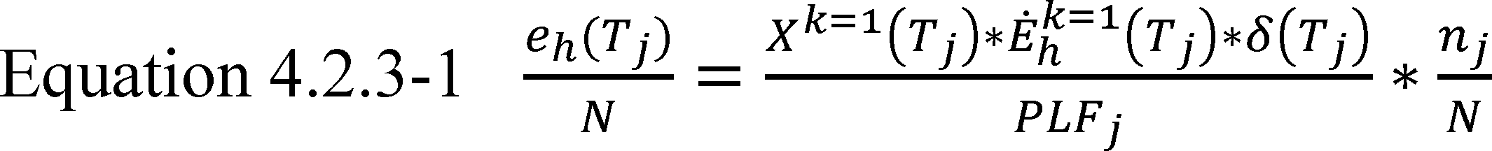
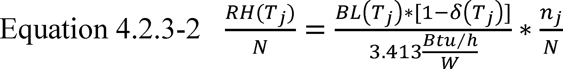
Where:
Xk=1(Tj) = BL(Tj)/Q̇hk=1(Tj), the heating mode low capacity load factor for temperature bin j, dimensionless.
PLFj = 1 − CDh · [ 1 − Xk=1(Tj) ], the part load factor, dimensionless.
δ′(Tj) = the low temperature cutoff factor, dimensionless.
Evaluate the heating mode cyclic degradation factor CDh as specified in section 3.8.1 of this appendix.
Determine the low temperature cut-out factor using
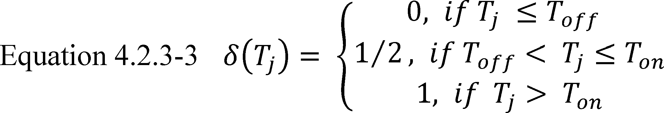
where Toff and Ton are defined in section 4.2.1 of this appendix. Use the calculations given in section 4.2.3.3 of this appendix, and not the above, if:
a. The heat pump locks out low capacity operation at low outdoor temperatures and
b. Tj is below this lockout threshold temperature.
4.2.3.2 Heat Pump Alternates Between High (k=2) and Low (k=1) Compressor Capacity To Satisfy the Building Heating Load at a Temperature Tj, Q̇hk=1(Tj) <BL(Tj) <Q̇hk=2(Tj)

Xk=2(Tj) = 1 − Xk=1(Tj) the heating mode, high capacity load factor for temperaturebinj, dimensionless.
Determine the low temperature cut-out factor, δ′(Tj), using Equation 4.2.3-3.
4.2.3.3 Heat Pump Only Operates at High (k=2) Compressor Capacity at Temperature Tj and its Capacity Is Greater Than the Building Heating Load, BL(Tj) <Q̇hk=2(Tj)
This section applies to units that lock out low compressor capacity operation at low outdoor temperatures.
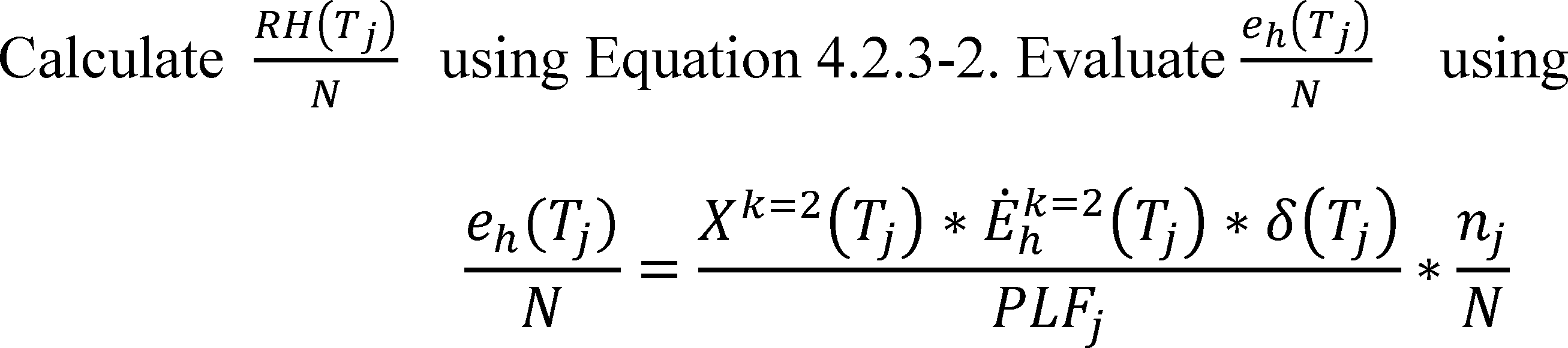
Where:
Xk=2(Tj)= BL(Tj)/Q̇hk=2(Tj). PLFj = 1 − CDh(k = 2) * [1 − Xk=1(Tj)
If the H1C2 test described in section 3.6.3 and Table 13 of this appendix is not conducted, set CDh (k=2) equal to the default value specified in section 3.8.1 of this appendix.
Determine the low temperature cut-out factor, δ(Tj), using Equation 4.2.3-3.
4.2.3.4 Heat Pump Must Operate Continuously at High (k=2) Compressor Capacity at Temperature Tj, BL(Tj) ≥Q̇hk=2(Tj)

4.2.4 Additional Steps for Calculating the HSPF of a Heat Pump Having a Variable-Speed Compressor
Calculate HSPF using Equation 4.2-1. Evaluate the space heating capacity, Q̇hk=1(Tj), and electrical power consumption, Ėhk=1(Tj), of the heat pump when operating at minimum compressor speed and outdoor temperature Tj using


where Q̇hk=1(62) and Ėhk=1(62) are determined from the H01 test, Q̇hk=1(47) and Ėhk=1(47) are determined from the H11 test, and all four quantities are calculated as specified in section 3.7 of this appendix.
Evaluate the space heating capacity, Q̇hk=2(Tj), and electrical power consumption, Ėhk=2(Tj), of the heat pump when operating at full compressor speed and outdoor temperature Tj by solving Equations 4.2.2-3 and 4.2.2-4, respectively, for k=2. For Equation 4.2.2-3, use Q̇hcalck=2(47) to represent Q̇hk=2(47), and for Equation 4.2.2-4, use Ėhcalck=2(47) to represent Ėhcalck=2(47) - evaluate Q̇hcalck=2(47) and Ėhcalck=2(47) as specified in section 3.6.4b of this appendix.


where Q̇hk=v(35) and Ėhk=v(35) are determined from the H2V test and calculated as specified in section 3.9 of this appendix. Approximate the slopes of the k=v intermediate speed heating capacity and electrical power input curves, MQ and ME, as follows:
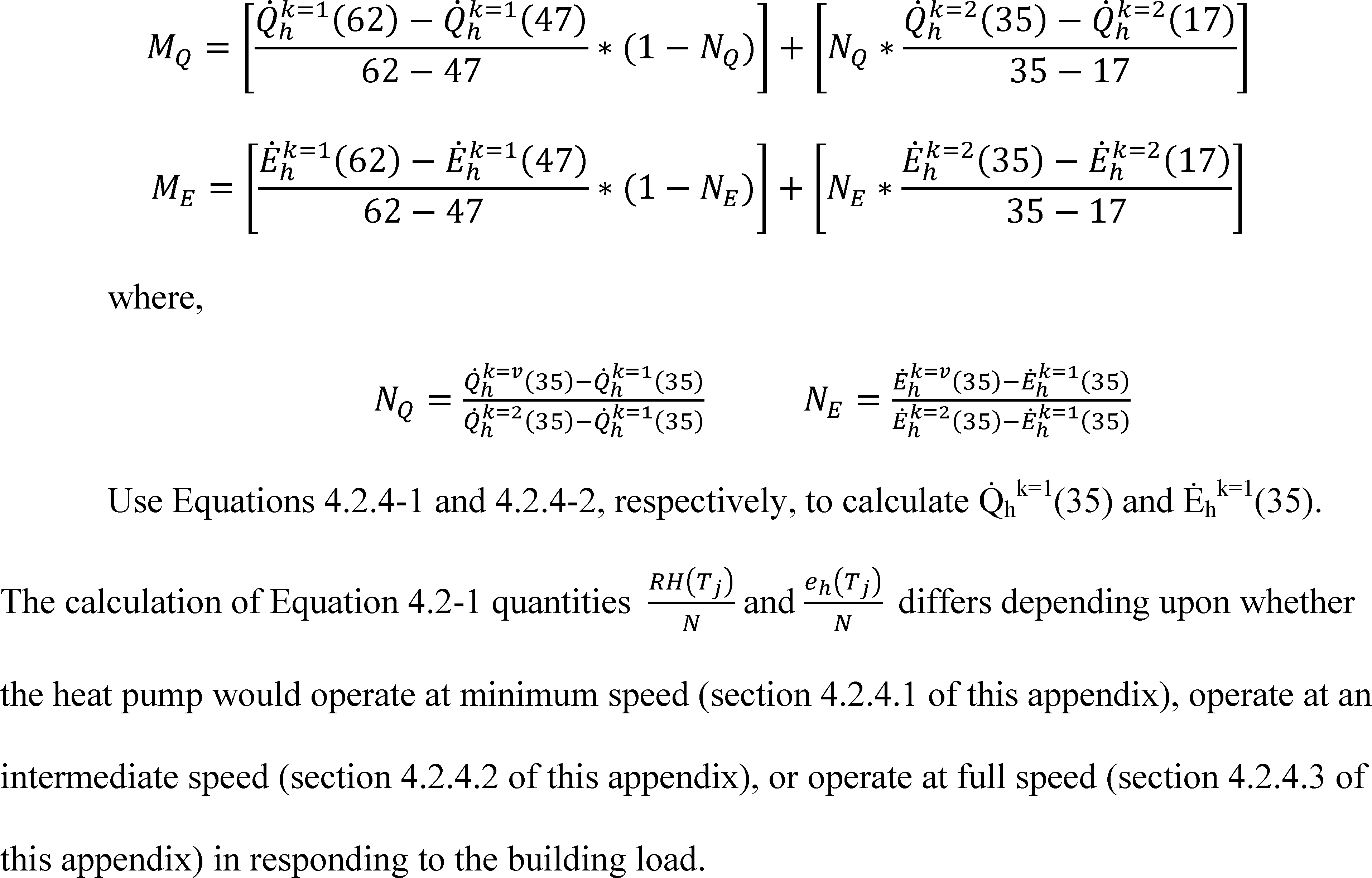
4.2.4.1 Steady-State Space Heating Capacity When Operating at Minimum Compressor Speed Is Greater Than or Equal to the Building Heating Load at Temperature Tj, Q̇hk=1(Tj ≥BL(Tj)
Evaluate the Equation 4.2-1 quantities

as specified in section 4.2.3.1 of this appendix. Except now use Equations 4.2.4-1 and 4.2.4-2 to evaluate Q̇hk=1(Tj) and Ėhk=1(Tj), respectively, and replace section 4.2.3.1 references to “low capacity” and section 3.6.3 of this appendix with “minimum speed” and section 3.6.4 of this appendix. Also, the last sentence of section 4.2.3.1 of this appendix does not apply.
4.2.4.2 Heat Pump Operates at an Intermediate Compressor Speed (k=i) in Order To Match the Building Heating Load at a Temperature Tj, Q̇hk=1(Tj) <BL(Tj) <Q̇hk=2(Tj)

and δ(Tj) is evaluated using Equation 4.2.3-3 while,
Q̇hk=i(Tj) = BL(Tj), the space heating capacity delivered by the unit in matching the building load at temperature (Tj), Btu/h. The matching occurs with the heat pump operating at compressor speed k=i.
COPk=i(Tj) = the steady-state coefficient of performance of the heat pump when operating at compressor speed k=i and temperature Tj, dimensionless.
For each temperature bin where the heat pump operates at an intermediate compressor speed, determine COPk=i(Tj) using the following equations,
For each temperature bin where Q̇hk=1(Tj) <BL(Tj) <Q̇hk=v(Tj),
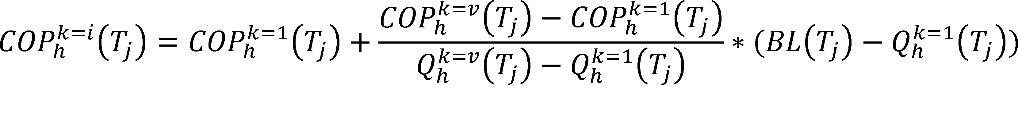
For each temperature bin where Q̇hk=v(Tj) ≤BL(Tj) <Q̇hk=2(Tj),

Where:
COPhk=1(Tj) is the steady-state coefficient of performance of the heat pump when operating at minimum compressor speed and temperature Tj, dimensionless, calculated using capacity Q̇hk=1(Tj) calculated using Equation 4.2.4-1 and electrical power consumption Ėhk=1(Tj) calculated using Equation 4.2.4-2;
COPhk=v(Tj) is the steady-state coefficient of performance of the heat pump when operating at intermediate compressor speed and temperature Tj, dimensionless, calculated using capacity Q̇hk=v(Tj) calculated using Equation 4.2.4-3 and electrical power consumption Ėhk=v(Tj) calculated using Equation 4.2.4-4;
COPhk=2(Tj) is the steady-state coefficient of performance of the heat pump when operating at full compressor speed and temperature Tj, dimensionless, calculated using capacity Q̇hk=2(Tj) and electrical power consumption Ėhk=2(Tj), both calculated as described in section 4.2.4; and
BL(Tj) is the building heating load at temperature Tj, Btu/h.
4.2.4.3 Heat Pump Must Operate Continuously at Full (k=2) Compressor Speed at Temperature Tj, BL(Tj) ≥Q̇hk=2(Tj)
Evaluate the Equation 4.2-1 Quantities
as specified in section 4.2.3.4 of this appendix with the understanding that Q̇hk=2(Tj) and Ėhk=2(Tj) correspond to full compressor speed operation and are derived from the results of the specified section 3.6.4 tests of this appendix.
4.2.5 Heat Pumps Having a Heat Comfort Controller
Heat pumps having heat comfort controllers, when set to maintain a typical minimum air delivery temperature, will cause the heat pump condenser to operate less because of a greater contribution from the resistive elements. With a conventional heat pump, resistive heating is only initiated if the heat pump condenser cannot meet the building load (i.e., is delayed until a second stage call from the indoor thermostat). With a heat comfort controller, resistive heating can occur even though the heat pump condenser has adequate capacity to meet the building load (i.e., both on during a first stage call from the indoor thermostat). As a result, the outdoor temperature where the heat pump compressor no longer cycles (i.e., starts to run continuously), will be lower than if the heat pump did not have the heat comfort controller.
4.2.5.1 Blower Coil System Heat Pump Having a Heat Comfort Controller: Additional Steps for Calculating the HSPF of a Heat Pump Having a Single-Speed Compressor and Either a Fixed-Speed Indoor Blower or a Constant-Air-Volume-Rate Indoor Blower Installed, or a Coil-Only System Heat Pump
Calculate the space heating capacity and electrical power of the heat pump without the heat comfort controller being active as specified in section 4.2.1 of this appendix (Equations 4.2.1-4 and 4.2.1-5) for each outdoor bin temperature, Tj, that is listed in Table 20. Denote these capacities and electrical powers by using the subscript “hp” instead of “h.” Calculate the mass flow rate (expressed in pounds-mass of dry air per hour) and the specific heat of the indoor air (expressed in Btu/lbmda · °F) from the results of the H1 test using:

where V̇̅s, V̇̅mx, v′n (or vn), and Wn are defined following Equation 3-1. For each outdoor bin temperature listed in Table 20, calculate the nominal temperature of the air leaving the heat pump condenser coil using,

Evaluate eh(Tj/N), RH(Tj)/N, X(Tj), PLFj, and δ(Tj) as specified in section 4.2.1 of this appendix. For each bin calculation, use the space heating capacity and electrical power from Case 1 or Case 2, whichever applies.
Case 1. For outdoor bin temperatures where To(Tj) is equal to or greater than TCC (the maximum supply temperature determined according to section 3.1.9 of this appendix), determine Q̇h(Tj) and Ėh(Tj) as specified in section 4.2.1 of this appendix (i.e., Q̇h(Tj) = Q̇hp(Tj) and Ėhp(Tj) = Ėhp(Tj)). Note: Even though To(Tj) ≥Tcc, resistive heating may be required; evaluate Equation 4.2.1-2 for all bins.
Case 2. For outdoor bin temperatures where To(Tj) >Tcc, determine Q̇h(Tj) and Ėh(Tj) using,
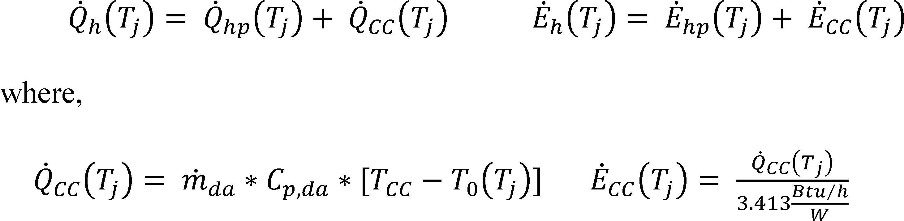
Even though To(Tj) Tcc, additional resistive heating may be required; evaluate Equation 4.2.1-2 for all bins.
4.2.5.2 Heat Pump Having a Heat Comfort Controller: Additional Steps for Calculating the HSPF of a Heat Pump Having a Single-Speed Compressor and a Variable-Speed, Variable-Air-Volume-Rate Indoor Blower
Calculate the space heating capacity and electrical power of the heat pump without the heat comfort controller being active as specified in section 4.2.2 of this appendix (Equations 4.2.2-1 and 4.2.2-2) for each outdoor bin temperature, Tj, that is listed in Table 20. Denote these capacities and electrical powers by using the subscript “hp” instead of “h.” Calculate the mass flow rate (expressed in pounds-mass of dry air per hour) and the specific heat of the indoor air (expressed in Btu/lbmda · °F) from the results of the H12 test using:
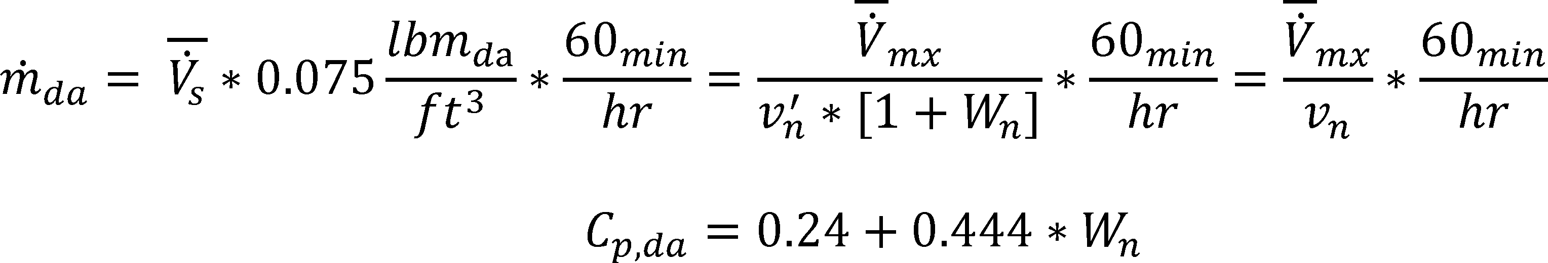
where V̇̅S, V̇̅mx, v′n (or vn), and Wn are defined following Equation 3-1. For each outdoor bin temperature listed in Table 20, calculate the nominal temperature of the air leaving the heat pump condenser coil using,
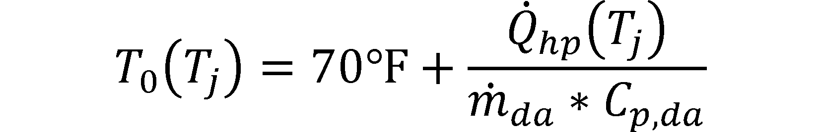
Evaluate eh(Tj)/N, RH(Tj)/N, X(Tj), PLFj, and δ(Tj) as specified in section 4.2.1 of this appendix with the exception of replacing references to the H1C test and section 3.6.1 of this appendix with the H1C1 test and section 3.6.2 of this appendix. For each bin calculation, use the space heating capacity and electrical power from Case 1 or Case 2, whichever applies.
Case 1. For outdoor bin temperatures where To(Tj) is equal to or greater than TCC (the maximum supply temperature determined according to section 3.1.9 of this appendix), determine Q̇h(Tj) and Ėh(Tj) as specified in section 4.2.2 of this appendix (i.e. Q̇h(Tj) = Q̇hp(Tj) and Ėh(Tj) = Ėhp(Tj)). Note: Even though To(Tj) ≥TCC, resistive heating may be required; evaluate Equation 4.2.1-2 for all bins.
Case 2. For outdoor bin temperatures where To(Tj) TCC, determine Q̇h(Tj) and Ėh(Tj) using,
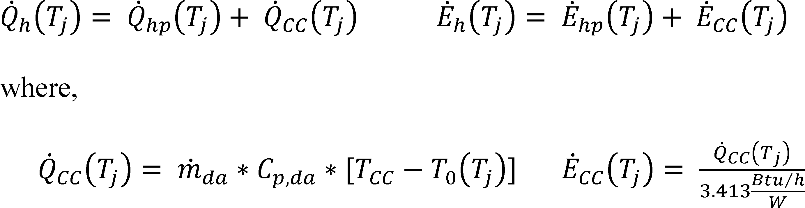
Even though To(Tj) Tcc, additional resistive heating may be required; evaluate Equation 4.2.1-2 for all bins.
4.2.5.3 Heat Pumps Having a Heat Comfort Controller: Additional Steps for Calculating the HSPF of a Heat Pump Having a Two-Capacity Compressor
Calculate the space heating capacity and electrical power of the heat pump without the heat comfort controller being active as specified in section 4.2.3 of this appendix for both high and low capacity and at each outdoor bin temperature, Tj, that is listed in Table 20. Denote these capacities and electrical powers by using the subscript “hp” instead of “h.” For the low capacity case, calculate the mass flow rate (expressed in pounds-mass of dry air per hour) and the specific heat of the indoor air (expressed in Btu/lbmda · °F) from the results of the H11 test using:
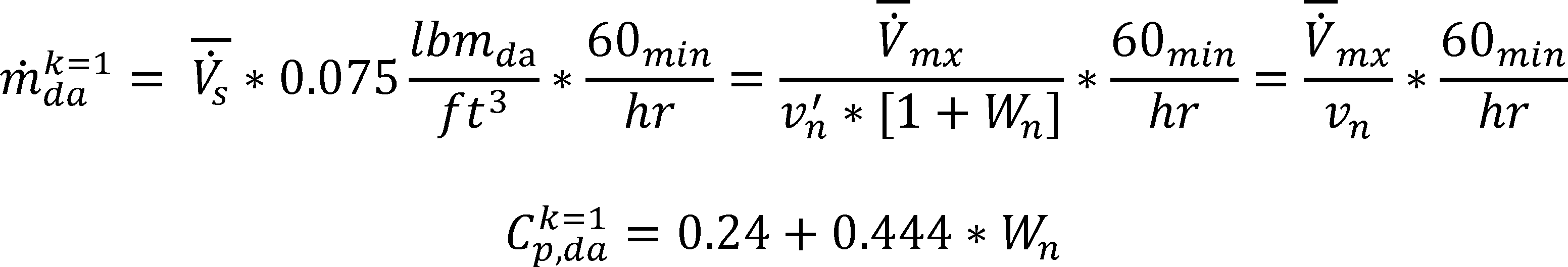
where V̇̅s, V̇̅mx, v′n (or vn), and Wn are defined following Equation 3-1. For each outdoor bin temperature listed in Table 20, calculate the nominal temperature of the air leaving the heat pump condenser coil when operating at low capacity using,
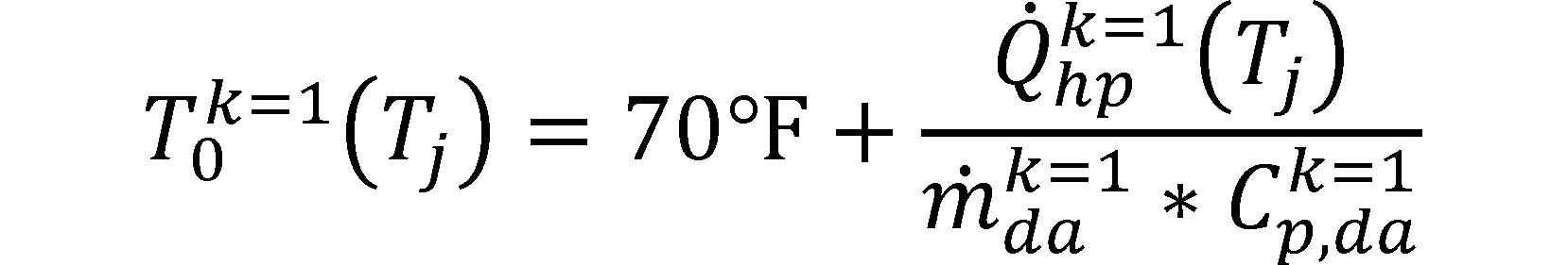
Repeat the above calculations to determine the mass flow rate (ṁdak=2) and the specific heat of the indoor air (Cp,dak=2) when operating at high capacity by using the results of the H12 test. For each outdoor bin temperature listed in Table 20, calculate the nominal temperature of the air leaving the heat pump condenser coil when operating at high capacity using,

Evaluate eh(Tj)/N, RH(Tj)/N, Xk=1(Tj), and/or Xk=2(Tj), PLFj, and δ′(Tj) or δ″(Tj) as specified in section 4.2.3.1. 4.2.3.2, 4.2.3.3, or 4.2.3.4 of this appendix, whichever applies, for each temperature bin. To evaluate these quantities, use the low-capacity space heating capacity and the low-capacity electrical power from Case 1 or Case 2, whichever applies; use the high-capacity space heating capacity and the high-capacity electrical power from Case 3 or Case 4, whichever applies.
Case 1. For outdoor bin temperatures where Tok=1(Tj) is equal to or greater than TCC (the maximum supply temperature determined according to section 3.1.9 of this appendix), determine Q̇hk=1(Tj) and Ėhk=1(Tj) as specified in section 4.2.3 of this appendix (i.e., Q̇hk=1(Tj) = Q̇hpk=1(Tj) and Ėhk=1(Tj) = Ėhpk=1(Tj).
Even though Tok=1(Tj) ≥TCC, resistive heating may be required; evaluate RH(Tj)/N for all bins.
Case 2. For outdoor bin temperatures where Tok=1(Tj) TCC, determine Q̇hk=1(Tj) and Ėhk=1(Tj) using,

Even though Tok=1(Tj) ≥Tcc, additional resistive heating may be required; evaluate RH(Tj)/N for all bins.
Case 3. For outdoor bin temperatures where Tok=2(Tj) is equal to or greater than TCC, determine Q̇hk=2(Tj) and Ėhk=2(Tj) as specified in section 4.2.3 of this appendix (i.e., Q̇hk=2(Tj) = Q̇hpk=2(Tj) and Ėhk=2(Tj) = Ėhpk=2(Tj)).
Even though Tok=2(Tj) <TCC, resistive heating may be required; evaluate RH(Tj)/N for all bins.
Case 4. For outdoor bin temperatures where Tok=2(Tj) <TCC, determine Q̇hk=2(Tj) and Ėhk=2(Tj) using,

Even though Tok=2(Tj) <Tcc, additional resistive heating may be required; evaluate RH(Tj)/N for all bins.
4.2.5.4 Heat Pumps Having a Heat Comfort Controller: Additional Steps for Calculating the HSPF of a Heat Pump Having a Variable-Speed Compressor. [Reserved]
4.2.6 Additional Steps for Calculating the HSPF of a Heat Pump Having a Triple-Capacity Compressor
The only triple-capacity heat pumps covered are triple-capacity, northern heat pumps. For such heat pumps, the calculation of the Eq. 4.2-1 quantities

differ depending on whether the heat pump would cycle on and off at low capacity (section 4.2.6.1 of this appendix), cycle on and off at high capacity (section 4.2.6.2 of this appendix), cycle on and off at booster capacity (section 4.2.6.3 of this appendix), cycle between low and high capacity (section 4.2.6.4 of this appendix), cycle between high and booster capacity (section 4.2.6.5 of this appendix), operate continuously at low capacity (4.2.6.6 of this appendix), operate continuously at high capacity (section 4.2.6.7 of this appendix), operate continuously at booster capacity (section 4.2.6.8 of this appendix), or heat solely using resistive heating (also section 4.2.6.8 of this appendix) in responding to the building load. As applicable, the manufacturer must supply information regarding the outdoor temperature range at which each stage of compressor capacity is active. As an informative example, data may be submitted in this manner: At the low (k=1) compressor capacity, the outdoor temperature range of operation is 40 °F ≤ T ≤ 65 °F; At the high (k=2) compressor capacity, the outdoor temperature range of operation is 20 °F ≤ T ≤ 50 °F; At the booster (k=3) compressor capacity, the outdoor temperature range of operation is −20 °F ≤ T ≤ 30 °F.
a. Evaluate the space heating capacity and electrical power consumption of the heat pump when operating at low compressor capacity and outdoor temperature Tj using the equations given in section 4.2.3 of this appendix for Q̇hk=1(Tj) and Ėhk=1 (Tj)) In evaluating the section 4.2.3 equations, Determine Q̇hk=1(62) and Ėhk=1(62) from the H01 test, Q̇hk=1(47) and Ėhk=1(47) from the H11 test, and Q̇hk=2(47) and Ėhk=2(47) from the H12 test. Calculate all four quantities as specified in section 3.7 of this appendix. If, in accordance with section 3.6.6 of this appendix, the H31 test is conducted, calculate Q̇hk=1(17) and Ėhk=1(17) as specified in section 3.10 of this appendix and determine Q̇hk=1(35) and Ėhk=1(35) as specified in section 3.6.6 of this appendix.
b. Evaluate the space heating capacity and electrical power consumption (Q̇hk=2(Tj) and Ėhk=2 (Tj)) of the heat pump when operating at high compressor capacity and outdoor temperature Tj by solving Equations 4.2.2-3 and 4.2.2-4, respectively, for k=2. Determine Q̇hk=1(62) and Ėhk=1(62) from the H01 test, Q̇hk=1(47) and Ėhk=1(47) from the H11 test, and Q̇hk=2(47) and Ėhk=2(47) from the H12 test, evaluated as specified in section 3.7 of this appendix. Determine the equation input for Q̇hk=2(35) and Ėhk=2(35) from the H22, evaluated as specified in section 3.9.1 of this appendix. Also, determine Q̇hk=2(17) and Ėhk=2(17) from the H32 test, evaluated as specified in section 3.10 of this appendix.
c. Evaluate the space heating capacity and electrical power consumption of the heat pump when operating at booster compressor capacity and outdoor temperature Tj using
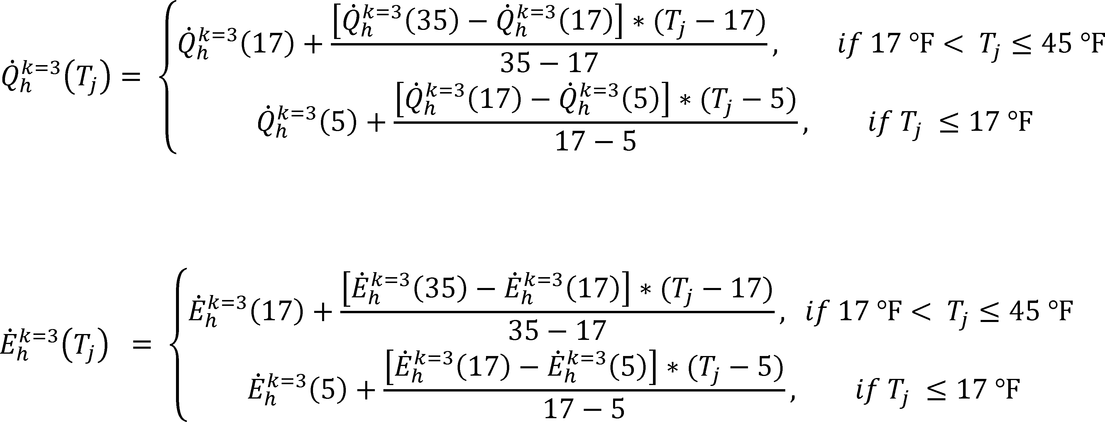
Determine Q̇hk=3(17) and Ėhk=3(17) from the H33 test and determine Q̇hk=2(5) and Ėhk=3(5) from the H43 test. Calculate all four quantities as specified in section 3.10 of this appendix. Determine the equation input for Q̇hk=3(35) and Ėhk=3(35) as specified in section 3.6.6 of this appendix.
4.2.6.1 Steady-State Space Heating Capacity when Operating at Low Compressor Capacity is Greater than or Equal to the Building Heating Load at Temperature Tj, Q̇hk=1(Tj) ≥BL(Tj)., and the heat pump permits low compressor capacity at Tj.
Evaluate the quantities

using Eqs. 4.2.3-1 and 4.2.3-2, respectively. Determine the equation inputs Xk=1(Tj), PLFj, and δ′(Tj) as specified in section 4.2.3.1 of this appendix. In calculating the part load factor, PLFj, use the low-capacity cyclic-degradation coefficient CDh, [or equivalently, CDh(k=1)] determined in accordance with section 3.6.6 of this appendix.
4.2.6.2 Heat Pump Only Operates at High (k=2) Compressor Capacity at Temperature Tj and Its Capacity Is Greater Than or Equal to the Building Heating Load, BL(Tj) <Q̇hk=2(Tj)
Evaluate the quantities

as specified in section 4.2.3.3 of this appendix. Determine the equation inputs Xk=2(Tj), PLFj, and δ′(Tj) as specified in section 4.2.3.3 of this appendix. In calculating the part load factor, PLFj, use the high-capacity cyclic-degradation coefficient, CDh(k=2) determined in accordance with section 3.6.6 of this appendix.
4.2.6.3 Heat Pump Only Operates at High (k=3) Compressor Capacity at Temperature Tj and Its Capacity Is Greater Than or Equal to the Building Heating Load, BL(Tj) ≤Q̇hk=3(Tj)

where:
Xk=3(Tj) = BL(Tj)/Q̇hk=3 (Tj) and PLFj = 1−CDh (k = 3) * [1−Xk=3 (Tj)
Determine the low temperature cut-out factor, δ′(Tj), using Eq. 4.2.3-3. Use the booster-capacity cyclic-degradation coefficient, CDh(k=3) determined in accordance with section 3.6.6 of this appendix.
4.2.6.4 Heat Pump Alternates Between High (k=2) and Low (k=1) Compressor Capacity to Satisfy the Building Heating Load at a Temperature Tj, Q̇hk=1(Tj) <BL(Tj) <Q̇hk=2(Tj)
Evaluate the quantities

as specified in section 4.2.3.2 of this appendix. Determine the equation inputs Xk=1(Tj), Xk=2(Tj), and δ′(Tj) as specified in section 4.2.3.2 of this appendix.
4.2.6.5 Heat Pump Alternates Between High (k=2) and Booster (k=3) Compressor Capacity To Satisfy the Building Heating Load at a Temperature Tj, Q̇hk=2(Tj) <BL(Tj) <Q̇hk=3(Tj)
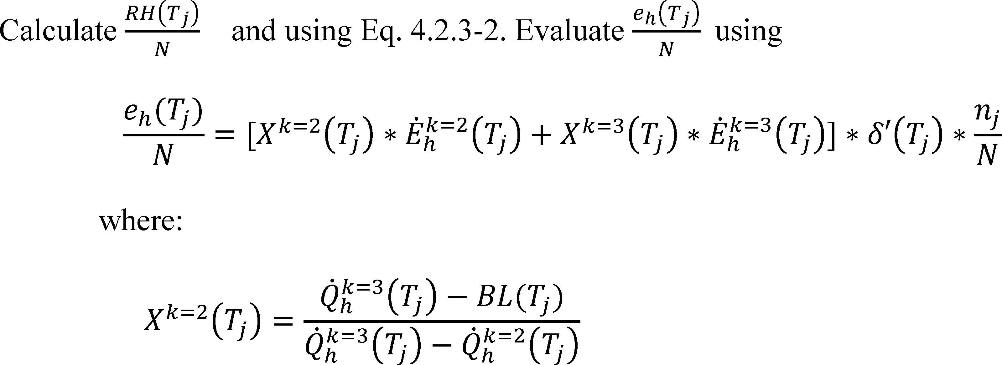
and Xk=3(Tj) = Xk=2(Tj) = the heating mode, booster capacity load factor for temperature bin j, dimensionless. Determine the low temperature cut-out factor, δ′(Tj), using Eq. 4.2.3-3.
4.2.6.6 Heat Pump Only Operates at Low (k=1) Capacity at Temperature Tj and Its Capacity Is Less Than the Building Heating Load, BL(Tj) > Q̇hk=1(Tj)

where the low temperature cut-out factor, δ′(Tj), is calculated using Eq. 4.2.3-3.
4.2.6.7 Heat Pump Only Operates at High (k=2) Capacity at Temperature Tj and Its Capacity Is Less Than the Building Heating Load, BL(Tj) > Q̇hk=2(Tj)
Evaluate the quantities

as specified in section 4.2.3.4 of this appendix. Calculate δ″(Tj) using the equation given in section 4.2.3.4 of this appendix.
4.2.6.8 Heat Pump Only Operates at Booster (k=3) Capacity at Temperature Tj and Its Capacity Is Less Than the Building Heating Load, BL(Tj) > Q̇hk=3(Tj) or the System Converts to Using Only Resistive Heating

where δ″(Tj) is calculated as specified in section 4.2.3.4 of this appendix if the heat pump is operating at its booster compressor capacity. If the heat pump system converts to using only resistive heating at outdoor temperature Tj, set δ′(Tj) equal to zero.
4.2.7 Additional Steps for Calculating the HSPF of a Heat Pump Having a Single Indoor Unit With Multiple Indoor Blowers
The calculation of the Eq. 4.2-1 quantities eh(Tj)/N and RH(Tj)/N are evaluated as specified in the applicable subsection.
4.2.7.1 For Multiple Indoor Blower Heat Pumps That Are Connected to a Singular, Single-Speed Outdoor Unit
a. Calculate the space heating capacity, Q̇hk=1(Tj), and electrical power consumption, Ėhk=1(Tj), of the heat pump when operating at the heating minimum air volume rate and outdoor temperature Tj using Eqs. 4.2.2-3 and 4.2.2-4, respectively. Use these same equations to calculate the space heating capacity, Q̇hk=2(Tj) and electrical power consumption, Ėhk=2(Tj), of the test unit when operating at the heating full-load air volume rate and outdoor temperature Tj. In evaluating Eqs. 4.2.2-3 and 4.2.2- 4, determine the quantities Q̇hk=1(47) and Ėhk=1(47) from the H11 test; determine Q̇hk=2 (47) and Ėhk=2(47) from the H12 test. Evaluate all four quantities according to section 3.7 of this appendix. Determine the quantities Q̇hk=1(35) and Ėhk=1(35) as specified in section 3.6.2 of this appendix. Determine Q̇hk=2(35) and Ėhk=2(35) from the H22 frost accumulation test as calculated according to section 3.9.1 of this appendix. Determine the quantities Q̇hk=1(17) and Ėhk=1(17) from the H31 test, and Q̇hk=2(17) and Ėhk=2(17) from the H32 test. Evaluate all four quantities according to section 3.10 of this appendix. Refer to section 3.6.2 and Table 12 of this appendix for additional information on the referenced laboratory tests.
b. Determine the heating mode cyclic degradation coefficient, CDh, as per sections 3.6.2 and 3.8 to 3.8.1 of this appendix. Assign this same value to CDh(k = 2).
c. Except for using the above values of Q̇hk=1(Tj), Ėhk=1(Tj), Q̇hk=2(Tj), Ėhk=2(Tj), CDh, and CDh(k = 2), calculate the quantities eh(Tj)/N as specified in section 4.2.3.1 of this appendix for cases where Q̇hk=1(Tj) ≥ BL(Tj). For all other outdoor bin temperatures, Tj, calculate eh(Tj)/N and RHh(Tj)/N as specified in section 4.2.3.3 of this appendix if Q̇hk=2(Tj) > BL(Tj) or as specified in section 4.2.3.4 of this appendix if Q̇hk=2(Tj) ≤ BL(Tj).
4.2.7.2 For Multiple Indoor Blower Heat Pumps Connected to Either a Single Outdoor Unit With a Two-capacity Compressor or to Two Separate Single-Speed Outdoor Units of Identical Model, calculate the quantities eh(Tj)/N and RH(Tj)/N as specified in section 4.2.3 of this appendix.
4.3 Calculations of Off-mode Power Consumption
For central air conditioners and heat pumps with a cooling capacity of:
Less than 36,000 Btu/h, determine the off mode represented value, PW,OFF, with the following equation:
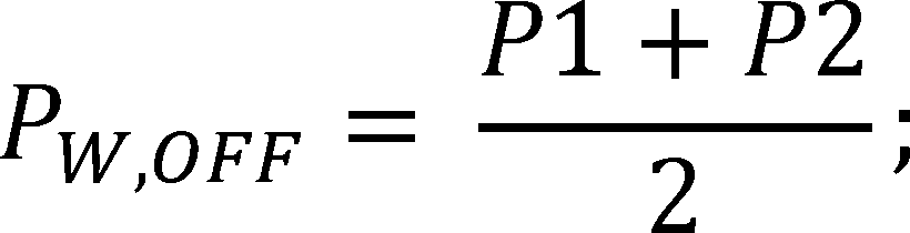
greater than or equal to 36,000 Btu/h, calculate the capacity scaling factor according to:
where Q̇C(95) is the total cooling capacity at the A or A2 test condition, and determine the off mode represented value, PW,OFF, with the following equation:
4.4 Rounding of SEER and HSPF for Reporting Purposes
After calculating SEER according to section 4.1 of this appendix and HSPF according to section 4.2 of this appendix round the values off as specified per § 430.23(m) of title 10 of the Code of Federal Regulations.

Table 22 - Representative Cooling and Heating Load Hours for Each Generalized Climatic Region
| Climatic region | Cooling load hours
CLHR | Heating load hours
HLHR |
|---|---|---|
| I | 2,400 | 750 |
| II | 1,800 | 1,250 |
| III | 1,200 | 1,750 |
| IV | 800 | 2,250 |
| Rating Values | 1,000 | 2,080 |
| V | 400 | 2,750 |
| VI | 200 | 2,750 |
4.5 Calculations of the SHR, Which Should Be Computed for Different Equipment Configurations and Test Conditions Specified in Table 23
Table 23 - Applicable Test Conditions For Calculation of the Sensible Heat Ratio
| Equipment configuration | Reference
table Number of appendix M | SHR computation with results
from | Computed values |
|---|---|---|---|
| Units Having a Single-Speed Compressor and a Fixed-Speed Indoor blower, a Constant Air Volume Rate Indoor blower, or No Indoor blower | 4 | B Test | SHR(B). |
| Units Having a Single-Speed Compressor That Meet the section 3.2.2.1 Indoor Unit Requirements | 5 | B2 and B1 Tests | SHR(B1), SHR(B2). |
| Units Having a Two-Capacity Compressor | 6 | B2 and B1 Tests | SHR(B1), SHR(B2). |
| Units Having a Variable-Speed Compressor | 7 | B2 and B1 Tests | SHR(B1), SHR(B2). |
The SHR is defined and calculated as follows:

Where both the total and sensible cooling capacities are determined from the same cooling mode test and calculated from data collected over the same 30-minute data collection interval.
4.6 Calculations of the Energy Efficiency Ratio (EER).
Calculate the energy efficiency ratio using.
where Q̇ck(T) and Ėck(T) are the space cooling capacity and electrical power consumption determined from the 30-minute data collection interval of the same steady-state wet coil cooling mode test and calculated as specified in section 3.3 of this appendix. Add the letter identification for each steady-state test as a subscript (e.g., EERA2) to differentiate among the resulting EER values.
[82 FR 1476, Jan. 5, 2017]
Appendix M1 to Subpart B of Part 430 - Uniform Test Method for Measuring the Energy Consumption of Central Air Conditioners and Heat Pumps
Prior to January 1, 2023, any representations, including compliance certifications, made with respect to the energy use, power, or efficiency of central air conditioners and central air conditioning heat pumps must be based on the results of testing pursuant to appendix M of this subpart.
On or after January 1, 2023, any representations, including compliance certifications, made with respect to the energy use, power, or efficiency of central air conditioners and central air conditioning heat pumps must be based on the results of testing pursuant to this appendix.
1 Scope and Definitions
1.1 Scope
This test procedure provides a method of determining SEER2, EER2, HSPF2 and PW,OFF for central air conditioners and central air conditioning heat pumps including the following categories:
(h) Split-system air conditioners, including single-split, multi-head mini-split, multi-split (including VRF), and multi-circuit systems
(i) Split-system heat pumps, including single-split, multi-head mini-split, multi-split (including VRF), and multi-circuit systems
(j) Single-package air conditioners
(k) Single-package heat pumps
(l) Small-duct, high-velocity systems (including VRF)
(m) Space-constrained products - air conditioners
(n) Space-constrained products - heat pumps
For the purposes of this appendix, the Department of Energy incorporates by reference specific sections of several industry standards, as listed in § 430.3. In cases where there is a conflict, the language of the test procedure in this appendix takes precedence over the incorporated standards.
All section references refer to sections within this appendix unless otherwise stated.
1.2 Definitions
Airflow-control settings are programmed or wired control system configurations that control a fan to achieve discrete, differing ranges of airflow - often designated for performing a specific function (e.g., cooling, heating, or constant circulation) - without manual adjustment other than interaction with a user-operable control (i.e., a thermostat) that meets the manufacturer specifications for installed-use. For the purposes of this appendix, manufacturer specifications for installed-use are those found in the product literature shipped with the unit.
Air sampling device is an assembly consisting of a manifold with several branch tubes with multiple sampling holes that draws an air sample from a critical location from the unit under test (e.g. indoor air inlet, indoor air outlet, outdoor air inlet, etc.).
Airflow prevention device denotes a device that prevents airflow via natural convection by mechanical means, such as an air damper box, or by means of changes in duct height, such as an upturned duct.
Aspirating psychrometer is a piece of equipment with a monitored airflow section that draws uniform airflow through the measurement section and has probes for measurement of air temperature and humidity.
Blower coil indoor unit means an indoor unit either with an indoor blower housed with the coil or with a separate designated air mover such as a furnace or a modular blower (as defined in appendix AA to this subpart).
Blower coil system refers to a split system that includes one or more blower coil indoor units.
Cased coil means a coil-only indoor unit with external cabinetry.
Ceiling-mount blower coil system means a split system for which a) the outdoor unit has a certified cooling capacity less than or equal to 36,000 Btu/h; b) the indoor unit(s) is/are shipped with manufacturer-supplied installation instructions that specify to secure the indoor unit only to the ceiling, within a furred-down space, or above a dropped ceiling of the conditioned space, with return air directly to the bottom of the unit without ductwork, or through the furred-down space, or optional insulated return air plenum that is shipped with the indoor unit; c) the installed height of the indoor unit is no more than 12 inches (not including condensate drain lines) and the installed depth (in the direction of airflow) of the indoor unit is no more than 30 inches; and d) supply air is discharged horizontally.
Coefficient of Performance (COP) means the ratio of the average rate of space heating delivered to the average rate of electrical energy consumed by the heat pump. Determine these rate quantities from a single test or, if derived via interpolation, determine at a single set of operating conditions. COP is a dimensionless quantity. When determined for a ducted coil-only system, COP must be calculated using the default values for heat output and power input of a fan motor specified in sections 3.7 and 3.9.1 of this appendix.
Coil-only indoor unit means an indoor unit that is distributed in commerce without an indoor blower or separate designated air mover. A coil-only indoor unit installed in the field relies on a separately installed furnace or a modular blower for indoor air movement.
Coil-only system means a system that includes only (one or more) coil-only indoor units.
Condensing unit removes the heat absorbed by the refrigerant to transfer it to the outside environment and consists of an outdoor coil, compressor(s), and air moving device.
Constant-air-volume-rate indoor blower means a fan that varies its operating speed to provide a fixed air-volume-rate from a ducted system.
Continuously recorded, when referring to a dry bulb measurement, dry bulb temperature used for test room control, wet bulb temperature, dew point temperature, or relative humidity measurements, means that the specified value must be sampled at regular intervals that are equal to or less than 15 seconds.
Cooling load factor (CLF) means the ratio having as its numerator the total cooling delivered during a cyclic operating interval consisting of one ON period and one OFF period, and as its denominator the total cooling that would be delivered, given the same ambient conditions, had the unit operated continuously at its steady-state, space-cooling capacity for the same total time (ON + OFF) interval.
Crankcase heater means any electrically powered device or mechanism for intentionally generating heat within and/or around the compressor sump volume. Crankcase heater control may be achieved using a timer or may be based on a change in temperature or some other measurable parameter, such that the crankcase heater is not required to operate continuously. A crankcase heater without controls operates continuously when the compressor is not operating.
Cyclic Test means a test where the unit's compressor is cycled on and off for specific time intervals. A cyclic test provides half the information needed to calculate a degradation coefficient.
Damper box means a short section of duct having an air damper that meets the performance requirements of section 2.5.7 of this appendix.
Degradation coefficient (CD) means a parameter used in calculating the part load factor. The degradation coefficient for cooling is denoted by CDc. The degradation coefficient for heating is denoted by CDh.
Demand-defrost control system means a system that defrosts the heat pump outdoor coil-only when measuring a predetermined degradation of performance. The heat pump's controls either:
(1) Monitor one or more parameters that always vary with the amount of frost accumulated on the outdoor coil (e.g., coil to air differential temperature, coil differential air pressure, outdoor fan power or current, optical sensors) at least once for every ten minutes of compressor ON-time when space heating; or
(2) Operate as a feedback system that measures the length of the defrost period and adjusts defrost frequency accordingly. In all cases, when the frost parameter(s) reaches a predetermined value, the system initiates a defrost. In a demand-defrost control system, defrosts are terminated based on monitoring a parameter(s) that indicates that frost has been eliminated from the coil. (Note: Systems that vary defrost intervals according to outdoor dry-bulb temperature are not demand-defrost systems.) A demand-defrost control system, which otherwise meets the requirements, may allow time-initiated defrosts if, and only if, such defrosts occur after 6 hours of compressor operating time.
Design heating requirement (DHR) predicts the space heating load of a residence when subjected to outdoor design conditions. Estimates for the minimum and maximum DHR are provided for six generalized U.S. climatic regions in section 4.2 of this appendix.
Dry-coil tests are cooling mode tests where the wet-bulb temperature of the air supplied to the indoor unit is maintained low enough that no condensate forms on the evaporator coil.
Ducted system means an air conditioner or heat pump that is designed to be permanently installed equipment and delivers conditioned air to the indoor space through a duct(s). The air conditioner or heat pump may be either a split-system or a single-package unit.
Energy efficiency ratio (EER) means the ratio of the average rate of space cooling delivered to the average rate of electrical energy consumed by the air conditioner or heat pump. Determine these rate quantities from a single test or, if derived via interpolation, determine at a single set of operating conditions. EER is expressed in units of

When determined for a ducted coil-only system, EER must include, from this appendix, the section 3.3 and 3.5.1 default values for the heat output and power input of a fan motor. The represented value of EER determined in accordance with appendix M1 is EER2.
Evaporator coil means an assembly that absorbs heat from an enclosed space and transfers the heat to a refrigerant.
Heat pump means a kind of central air conditioner that utilizes an indoor conditioning coil, compressor, and refrigerant-to-outdoor air heat exchanger to provide air heating, and may also provide air cooling, air dehumidifying, air humidifying, air circulating, and air cleaning.
Heat pump having a heat comfort controller means a heat pump with controls that can regulate the operation of the electric resistance elements to assure that the air temperature leaving the indoor section does not fall below a specified temperature. Heat pumps that actively regulate the rate of electric resistance heating when operating below the balance point (as the result of a second stage call from the thermostat) but do not operate to maintain a minimum delivery temperature are not considered as having a heat comfort controller.
Heating load factor (HLF) means the ratio having as its numerator the total heating delivered during a cyclic operating interval consisting of one ON period and one OFF period, and its denominator the heating capacity measured at the same test conditions used for the cyclic test, multiplied by the total time interval (ON plus OFF) of the cyclic-test.
Heating season means the months of the year that require heating, e.g., typically, and roughly, October through April.
Heating seasonal performance factor 2 (HSPF2) means the total space heating required during the heating season, expressed in Btu, divided by the total electrical energy consumed by the heat pump system during the same season, expressed in watt-hours. The HSPF2 used to evaluate compliance with 10 CFR 430.32(c) is based on Region IV and the sampling plan stated in 10 CFR 429.16(a). HSPF2 is determined in accordance with appendix M1.
Independent coil manufacturer (ICM) means a manufacturer that manufactures indoor units but does not manufacture single-package units or outdoor units.
Indoor unit means a separate assembly of a split system that includes -
(a) An arrangement of refrigerant-to-air heat transfer coil(s) for transfer of heat between the refrigerant and the indoor air,
(b) A condensate drain pan, and may or may not include,
(c) Sheet metal or plastic parts not part of external cabinetry to direct/route airflow over the coil(s),
(d) A cooling mode expansion device,
(e) External cabinetry, and
(f) An integrated indoor blower (i.e. a device to move air including its associated motor). A separate designated air mover that may be a furnace or a modular blower (as defined in appendix AA to the subpart) may be considered to be part of the indoor unit. A service coil is not an indoor unit.
Low-static blower coil system means a ducted multi-split or multi-head mini-split system for which all indoor units produce greater than 0.01 in. wc. and a maximum of 0.35 in. wc. external static pressure when operated at the cooling full-load air volume rate not exceeding 400 cfm per rated ton of cooling.
Mid-static blower coil system means a ducted multi-split or multi-head mini-split system for which all indoor units produce greater than 0.20 in. wc. and a maximum of 0.65 in. wc. when operated at the cooling full-load air volume rate not exceeding 400 cfm per rated ton of cooling.
Minimum-speed-limiting variable-speed heat pump means a heat pump for which the compressor speed (represented by revolutions per minute or motor power input frequency) is higher than its value for operation in a 47 °F ambient temperature for any bin temperature Tj for which the calculated heating load is less than the calculated intermediate-speed capacity.
Mobile home blower coil system means a split system that contains an outdoor unit and an indoor unit that meet the following criteria:
(1) Both the indoor and outdoor unit are shipped with manufacturer-supplied installation instructions that specify installation only in a mobile home with the home and equipment complying with HUD Manufactured Home Construction Safety Standard 24 CFR part 3280;
(2) The indoor unit cannot exceed 0.40 in. wc. when operated at the cooling full-load air volume rate not exceeding 400 cfm per rated ton of cooling; and
(3) The indoor and outdoor unit each must bear a label in at least 1⁄4 inch font that reads “For installation only in HUD manufactured home per Construction Safety Standard 24 CFR part 3280.”
Mobile home coil-only system means a coil-only split system that includes an outdoor unit and coil-only indoor unit that meet the following criteria:
(1) The outdoor unit is shipped with manufacturer-supplied installation instructions that specify installation only for mobile homes that comply with HUD Manufactured Home Construction Safety Standard 24 CFR part 3280,
(2) The coil-only indoor unit is shipped with manufacturer-supplied installation instructions that specify installation only in or with a mobile home furnace, modular blower, or designated air mover that complies with HUD Manufactured Home Construction Safety Standard 24 CFR part 3280, and has dimensions no greater than 20” wide, 34” high and 21” deep, and
(3) The coil-only indoor unit and outdoor unit each has a label in at least 1⁄4 inch font that reads “For installation only in HUD manufactured home per Construction Safety Standard 24 CFR part 3280.”
Multi-head mini-split system means a split system that has one outdoor unit and that has two or more indoor units connected with a single refrigeration circuit. The indoor units operate in unison in response to a single indoor thermostat.
Multiple-circuit (or multi-circuit) system means a split system that has one outdoor unit and that has two or more indoor units installed on two or more refrigeration circuits such that each refrigeration circuit serves a compressor and one and only one indoor unit, and refrigerant is not shared from circuit to circuit.
Multiple-split (or multi-split) system means a split system that has one outdoor unit and two or more coil-only indoor units and/or blower coil indoor units connected with a single refrigerant circuit. The indoor units operate independently and can condition multiple zones in response to at least two indoor thermostats or temperature sensors. The outdoor unit operates in response to independent operation of the indoor units based on control input of multiple indoor thermostats or temperature sensors, and/or based on refrigeration circuit sensor input (e.g., suction pressure).
Nominal capacity means t he capacity that is claimed by the manufacturer on the product name plate. Nominal cooling capacity is approximate to the air conditioner cooling capacity tested at A or A2 condition. Nominal heating capacity is approximate to the heat pump heating capacity tested in the H1N test.
Non-ducted indoor unit means an indoor unit that is designed to be permanently installed, mounted on room walls and/or ceilings, and that directly heats or cools air within the conditioned space.
Normalized Gross Indoor Fin Surface (NGIFS) means the gross fin surface area of the indoor unit coil divided by the cooling capacity measured for the A or A2 Test, whichever applies.
Off-mode power consumption means the power consumption when the unit is connected to its main power source but is neither providing cooling nor heating to the building it serves.
Off-mode season means, for central air conditioners other than heat pumps, the shoulder season and the entire heating season; and for heat pumps, the shoulder season only.
Outdoor unit means a separate assembly of a split system that transfers heat between the refrigerant and the outdoor air, and consists of an outdoor coil, compressor(s), an air moving device, and in addition for heat pumps, may include a heating mode expansion device, reversing valve, and/or defrost controls.
Outdoor unit manufacturer (OUM) means a manufacturer of single-package units, outdoor units, and/or both indoor units and outdoor units.
Part-load factor (PLF) means the ratio of the cyclic EER (or COP for heating) to the steady-state EER (or COP), where both EERs (or COPs) are determined based on operation at the same ambient conditions.
Seasonal energy efficiency ratio 2 (SEER2) means the total heat removed from the conditioned space during the annual cooling season, expressed in Btu's, divided by the total electrical energy consumed by the central air conditioner or heat pump during the same season, expressed in watt-hours. SEER2 is determined in accordance with appendix M1.
Service coil means an arrangement of refrigerant-to-air heat transfer coil(s), condensate drain pan, sheet metal or plastic parts to direct/route airflow over the coil(s), which may or may not include external cabinetry and/or a cooling mode expansion device, distributed in commerce solely for replacing an uncased coil or cased coil that has already been placed into service, and that has been labeled “for indoor coil replacement only” on the nameplate and in manufacturer technical and product literature. The model number for any service coil must include some mechanism (e.g., an additional letter or number) for differentiating a service coil from a coil intended for an indoor unit.
Shoulder season means the months of the year in between those months that require cooling and those months that require heating, e.g., typically, and roughly, April through May, and September through October.
Single-package unit means any central air conditioner or heat pump that has all major assemblies enclosed in one cabinet.
Single-split system means a split system that has one outdoor unit and one indoor unit connected with a single refrigeration circuit.
Small-duct, high-velocity system means a split system for which all indoor units are blower coil indoor units that produce at least 1.2 inches (of water column) of external static pressure when operated at the full-load air volume rate certified by the manufacturer of at least 220 scfm per rated ton of cooling.
Split system means any central air conditioner or heat pump that has at least two separate assemblies that are connected with refrigerant piping when installed. One of these assemblies includes an indoor coil that exchanges heat with the indoor air to provide heating or cooling, while one of the others includes an outdoor coil that exchanges heat with the outdoor air. Split systems may be either blower coil systems or coil-only systems.
Standard Air means dry air having a mass density of 0.075 lb/ft3.
Steady-state test means a test where the test conditions are regulated to remain as constant as possible while the unit operates continuously in the same mode.
Temperature bin means the 5 °F increments that are used to partition the outdoor dry-bulb temperature ranges of the cooling (≥65 °F) and heating (<65 °F) seasons.
Test condition tolerance means the maximum permissible difference between the average value of the measured test parameter and the specified test condition.
Test operating tolerance means the maximum permissible range that a measurement may vary over the specified test interval. The difference between the maximum and minimum sampled values must be less than or equal to the specified test operating tolerance.
Tested combination means a multi-head mini-split, multi-split, or multi-circuit system having the following features:
(1) The system consists of one outdoor unit with one or more compressors matched with between two and five indoor units;
(2) The indoor units must:
(i) Collectively, have a nominal cooling capacity greater than or equal to 95 percent and less than or equal to 105 percent of the nominal cooling capacity of the outdoor unit;
(ii) Each represent the highest sales volume model family, if this is possible while meeting all the requirements of this section. If this is not possible, one or more of the indoor units may represent another indoor model family in order that all the other requirements of this section are met.
(iii) Individually not have a nominal cooling capacity greater than 50 percent of the nominal cooling capacity of the outdoor unit, unless the nominal cooling capacity of the outdoor unit is 24,000 Btu/h or less;
(iv) Operate at fan speeds consistent with manufacturer's specifications; and
(v) All be subject to the same minimum external static pressure requirement while able to produce the same external static pressure at the exit of each outlet plenum when connected in a manifold configuration as required by the test procedure.
(3) Where referenced, “nominal cooling capacity” means, for indoor units, the highest cooling capacity listed in published product literature for 95 °F outdoor dry bulb temperature and 80 °F dry bulb, 67 °F wet bulb indoor conditions, and for outdoor units, the lowest cooling capacity listed in published product literature for these conditions. If incomplete or no operating conditions are published, use the highest (for indoor units) or lowest (for outdoor units) such cooling capacity available for sale.
Time-adaptive defrost control system is a demand-defrost control system that measures the length of the prior defrost period(s) and uses that information to automatically determine when to initiate the next defrost cycle.
Time-temperature defrost control systems initiate or evaluate initiating a defrost cycle only when a predetermined cumulative compressor ON-time is obtained. This predetermined ON-time is generally a fixed value (e.g., 30, 45, 90 minutes) although it may vary based on the measured outdoor dry-bulb temperature. The ON-time counter accumulates if controller measurements (e.g., outdoor temperature, evaporator temperature) indicate that frost formation conditions are present, and it is reset/remains at zero at all other times. In one application of the control scheme, a defrost is initiated whenever the counter time equals the predetermined ON-time. The counter is reset when the defrost cycle is completed.
In a second application of the control scheme, one or more parameters are measured (e.g., air and/or refrigerant temperatures) at the predetermined, cumulative, compressor ON-time. A defrost is initiated only if the measured parameter(s) falls within a predetermined range. The ON-time counter is reset regardless of whether or not a defrost is initiated. If systems of this second type use cumulative ON-time intervals of 10 minutes or less, then the heat pump may qualify as having a demand defrost control system (see definition).
Triple-capacity, northern heat pump means a heat pump that provides two stages of cooling and three stages of heating. The two common stages for both the cooling and heating modes are the low capacity stage and the high capacity stage. The additional heating mode stage is the booster capacity stage, which offers the highest heating capacity output for a given set of ambient operating conditions.
Triple-split system means a split system that is composed of three separate assemblies: An outdoor fan coil section, a blower coil indoor unit, and an indoor compressor section.
Two-capacity (or two-stage) compressor system means a central air conditioner or heat pump that has a compressor or a group of compressors operating with only two stages of capacity. For such systems, low capacity means the compressor(s) operating at low stage, or at low load test conditions. The low compressor stage that operates for heating mode tests may be the same or different from the low compressor stage that operates for cooling mode tests. For such systems, high capacity means the compressor(s) operating at high stage, or at full load test conditions.
Two-capacity, northern heat pump means a heat pump that has a factory or field-selectable lock-out feature to prevent space cooling at high-capacity. Two-capacity heat pumps having this feature will typically have two sets of ratings, one with the feature disabled and one with the feature enabled. The heat pump is a two-capacity northern heat pump only when this feature is enabled at all times. The certified indoor coil model number must reflect whether the ratings pertain to the lockout enabled option via the inclusion of an extra identifier, such as “+LO”. When testing as a two-capacity, northern heat pump, the lockout feature must remain enabled for all tests.
Uncased coil means a coil-only indoor unit without external cabinetry.
Variable refrigerant flow (VRF) system means a multi-split system with at least three compressor capacity stages, distributing refrigerant through a piping network to multiple indoor blower coil units each capable of individual zone temperature control, through proprietary zone temperature control devices and a common communications network. Note: Single-phase VRF systems less than 65,000 Btu/h are central air conditioners and central air conditioning heat pumps.
Variable-speed compressor system means a central air conditioner or heat pump that has a compressor that uses a variable-speed drive to vary the compressor speed to achieve variable capacities. Wall-mount blower coil system means a split system air conditioner or heat pump for which:
(a) The outdoor unit has a certified cooling capacity less than or equal to 36,000 Btu/h;
(b) The indoor unit(s) is/are shipped with manufacturer-supplied installation instructions that specify mounting only by:
(1) Securing the back side of the unit to a wall within the conditioned space, or
(2) Securing the unit to adjacent wall studs or in an enclosure, such as a closet, such that the indoor unit's front face is flush with a wall in the conditioned space;
(c) Has front air return without ductwork and is not capable of horizontal air discharge; and
(d) Has a height no more than 45 inches, a depth (perpendicular to the wall) no more than 22 inches (including tubing connections), and a width no more than 24 inches (parallel to the wall).
Wet-coil test means a test conducted at test conditions that typically cause water vapor to condense on the test unit evaporator coil.
2 Testing Overview and Conditions
(A) Test VRF systems using AHRI 1230-2010 (incorporated by reference, see § 430.3) and appendix M. Where AHRI 1230-2010 refers to the appendix C therein substitute the provisions of this appendix. In cases where there is a conflict, the language of the test procedure in this appendix takes precedence over AHRI 1230-2010.
For definitions use section 1 of appendix M and section 3 of AHRI 1230-2010. For rounding requirements, refer to § 430.23(m). For determination of certified ratings, refer to § 429.16 of this chapter.
For test room requirements, refer to section 2.1 of this appendix. For test unit installation requirements refer to sections 2.2.a, 2.2.b, 2.2.c, 2.2.1, 2.2.2, 2.2.3.a, 2.2.3.c, 2.2.4, 2.2.5, and 2.4 to 2.12 of this appendix, and sections 5.1.3 and 5.1.4 of AHRI 1230-2010. The “manufacturer's published instructions,” as stated in section 8.2 of ANSI/ASHRAE 37-2009 (incorporated by reference, see § 430.3) and “manufacturer's installation instructions” discussed in this appendix mean the manufacturer's installation instructions that come packaged with or appear in the labels applied to the unit. This does not include online manuals. Installation instructions that appear in the labels applied to the unit take precedence over installation instructions that are shipped with the unit.
For general requirements for the test procedure, refer to section 3.1 of this appendix, except for sections 3.1.3 and 3.1.4, which are requirements for indoor air volume and outdoor air volume. For indoor air volume and outdoor air volume requirements, refer instead to section 6.1.5 (except where section 6.1.5 refers to Table 8, refer instead to Table 4 of this appendix) and 6.1.6 of AHRI 1230-2010.
For the test method, refer to sections 3.3 to 3.5 and 3.7 to 3.13 of this appendix. For cooling mode and heating mode test conditions, refer to section 6.2 of AHRI 1230-2010. For calculations of seasonal performance descriptors, refer to section 4 of this appendix.
(B) For systems other than VRF, only a subset of the sections listed in this test procedure apply when testing and determining represented values for a particular unit. Table 1 shows the sections of the test procedure that apply to each system. This table is meant to assist manufacturers in finding the appropriate sections of the test procedure; the appendix sections rather than the table provide the specific requirements for testing, and given the varied nature of available units, manufacturers are responsible for determining which sections apply to each unit tested based on the model characteristics. To use this table, first refer to the sections listed under “all units”. Then refer to additional requirements based on:
(1) System configuration(s),
(2) The compressor staging or modulation capability, and
(3) Any special features.
Testing requirements for space-constrained products do not differ from similar equipment that is not space-constrained and thus are not listed separately in this table. Air conditioners and heat pumps are not listed separately in this table, but heating procedures and calculations apply only to heat pumps.


2.1 Test Room Requirements.
a. Test using two side-by-side rooms: An indoor test room and an outdoor test room. For multiple-split, single-zone-multi-coil or multi-circuit air conditioners and heat pumps, however, use as many indoor test rooms as needed to accommodate the total number of indoor units. These rooms must comply with the requirements specified in sections 8.1.2 and 8.1.3 of ANSI/ASHRAE 37-2009 (incorporated by reference, see § 430.3).
b. Inside these test rooms, use artificial loads during cyclic tests and frost accumulation tests, if needed, to produce stabilized room air temperatures. For one room, select an electric resistance heater(s) having a heating capacity that is approximately equal to the heating capacity of the test unit's condenser. For the second room, select a heater(s) having a capacity that is close to the sensible cooling capacity of the test unit's evaporator. Cycle the heater located in the same room as the test unit evaporator coil ON and OFF when the test unit cycles ON and OFF. Cycle the heater located in the same room as the test unit condensing coil ON and OFF when the test unit cycles OFF and ON.
2.2 Test Unit Installation Requirements.
a. Install the unit according to section 8.2 of ANSI/ASHRAE 37-2009 (incorporated by reference, see § 430.3), subject to the following additional requirements:
(1) When testing split systems, follow the requirements given in section 6.1.3.5 of AHRI 210/240-2008 (incorporated by reference, see § 430.3). For the vapor refrigerant line(s), use the insulation included with the unit; if no insulation is provided, use insulation meeting the specifications for the insulation in the installation instructions included with the unit by the manufacturer; if no insulation is included with the unit and the installation instructions do not contain provisions for insulating the line(s), fully insulate the vapor refrigerant line(s) with vapor proof insulation having an inside diameter that matches the refrigerant tubing and a nominal thickness of at least 0.5 inches. For the liquid refrigerant line(s), use the insulation included with the unit; if no insulation is provided, use insulation meeting the specifications for the insulation in the installation instructions included with the unit by the manufacturer; if no insulation is included with the unit and the installation instructions do not contain provisions for insulating the line(s), leave the liquid refrigerant line(s) exposed to the air for air conditioners and heat pumps that heat and cool; or, for heating-only heat pumps, insulate the liquid refrigerant line(s) with insulation having an inside diameter that matches the refrigerant tubing and a nominal thickness of at least 0.5 inches. However, these requirements do not take priority over instructions for application of insulation for the purpose of improving refrigerant temperature measurement accuracy as required by sections 2.10.2 and 2.10.3 of this appendix. Insulation must be the same for the cooling and heating tests.
(2) When testing split systems, if the indoor unit does not ship with a cooling mode expansion device, test the system using the device as specified in the installation instructions provided with the indoor unit. If none is specified, test the system using a fixed orifice or piston type expansion device that is sized appropriately for the system.
(3) When testing triple-split systems (see section 1.2 of this appendix, Definitions), use the tubing length specified in section 6.1.3.5 of AHRI 210/240-2008 (incorporated by reference, see § 430.3) to connect the outdoor coil, indoor compressor section, and indoor coil while still meeting the requirement of exposing 10 feet of the tubing to outside conditions;
(4) When testing split systems having multiple indoor coils, connect each indoor blower coil unit to the outdoor unit using:
(a) 25 feet of tubing, or
(b) Tubing furnished by the manufacturer, whichever is longer.
(5) When testing split systems having multiple indoor coils, expose at least 10 feet of the system interconnection tubing to the outside conditions. If they are needed to make a secondary measurement of capacity or for verification of refrigerant charge, install refrigerant pressure measuring instruments as described in section 8.2.5 of ANSI/ASHRAE 37-2009 (incorporated by reference, see § 430.3). Section 2.10 of this appendix specifies which secondary methods require refrigerant pressure measurements and section 2.2.5.5 of this appendix discusses use of pressure measurements to verify charge. At a minimum, insulate the low-pressure line(s) of a split system with insulation having an inside diameter that matches the refrigerant tubing and a nominal thickness of 0.5 inch.
b. For units designed for both horizontal and vertical installation or for both up-flow and down-flow vertical installations, use the orientation for testing specified by the manufacturer in the certification report. Conduct testing with the following installed:
(1) The most restrictive filter(s);
(2) Supplementary heating coils; and
(3) Other equipment specified as part of the unit, including all hardware used by a heat comfort controller if so equipped (see section 1 of this appendix, Definitions). For small-duct, high-velocity systems, configure all balance dampers or restrictor devices on or inside the unit to fully open or lowest restriction.
c. Testing a ducted unit without having an indoor air filter installed is permissible as long as the minimum external static pressure requirement is adjusted as stated in Table 4, note 3 (see section 3.1.4 of this appendix). Except as noted in section 3.1.10 of this appendix, prevent the indoor air supplementary heating coils from operating during all tests. For uncased coils, create an enclosure using 1 inch fiberglass foil-faced ductboard having a nominal density of 6 pounds per cubic foot. Or alternatively, construct an enclosure using sheet metal or a similar material and insulating material having a thermal resistance (“R” value) between 4 and 6 hr · ft2 · °F/Btu. Size the enclosure and seal between the coil and/or drainage pan and the interior of the enclosure as specified in installation instructions shipped with the unit. Also seal between the plenum and inlet and outlet ducts.
d. When testing a coil-only system, install a toroidal-type transformer to power the system's low-voltage components, complying with any additional requirements for the transformer mentioned in the installation manuals included with the unit by the system manufacturer. If the installation manuals do not provide specifications for the transformer, use a transformer having the following features:
(1) A nominal volt-amp rating such that the transformer is loaded between 25 and 90 percent of this rating for the highest level of power measured during the off mode test (section 3.13 of this appendix);
(2) Designed to operate with a primary input of 230 V, single phase, 60 Hz; and
(3) That provides an output voltage that is within the specified range for each low-voltage component. Include the power consumption of the components connected to the transformer as part of the total system power consumption during the off mode tests; do not include the power consumed by the transformer when no load is connected to it.
e. Test an outdoor unit with no match (i.e., that is not distributed in commerce with any indoor units) using a coil-only indoor unit with a single cooling air volume rate whose coil has:
(1) Round tubes of outer diameter no less than 0.375 inches, and
(2) A normalized gross indoor fin surface (NGIFS) no greater than 1.0 square inch per British thermal unit per hour (sq. in./Btu/hr). NGIFS is calculated as follows:
NGIFS = 2 × Lf × Wf × Nf ÷ Q̇c(95)
where,
Lf = Indoor coil fin length in inches, also height of the coil transverse to the tubes.
Wf = Indoor coil fin width in inches, also depth of the coil.
Nf = Number of fins.
Q̇c = the measured space cooling capacity of the tested outdoor unit/indoor unit combination as determined from the A2 or A Test whichever applies, Btu/h.
f. If the outdoor unit or the outdoor portion of a single-package unit has a drain pan heater to prevent freezing of defrost water, energize the heater, subject to control to de-energize it when not needed by the heater's thermostat or the unit's control system, for all tests.
g. If pressure measurement devices are connected to a cooling/heating heat pump refrigerant circuit, the refrigerant charge Mt that could potentially transfer out of the connected pressure measurement systems (transducers, gauges, connections, and lines) between operating modes must be less than 2 percent of the factory refrigerant charge listed on the nameplate of the outdoor unit. If the outdoor unit nameplate has no listed refrigerant charge, or the heat pump is shipped without a refrigerant charge, use a factory refrigerant charge equal to 30 ounces per ton of certified cooling capacity. Use Equation 2.2-1 to calculate Mt for heat pumps that have a single expansion device located in the outdoor unit to serve each indoor unit, and use Equation 2.2-2 to calculate Mt for heat pumps that have two expansion devices per indoor unit.


where:
Vi (i=2,3,4 . . .) = the internal volume of the pressure measurement system (pressure lines, fittings, and gauge and/or transducer) at the location i (as indicated in Table 2), (cubic inches)
fi (i=5,6) = 0 if the pressure measurement system is pitched upwards from the pressure tap location to the gauge or transducer, 1 if it is not.
ρ = the density associated with liquid refrigerant at 100 °F bubble point conditions (ounces per cubic inch)
Table 2 - Pressure Measurement Locations
| Location | |
|---|---|
| Compressor Discharge | 1 |
| Between Outdoor Coil and Outdoor Expansion Valve(s) | 2 |
| Liquid Service Valve | 3 |
| Indoor Coil Inlet | 4 |
| Indoor Coil Outlet | 5 |
| Common Suction Port (i.e., vapor service valve) | 6 |
| Compressor Suction | 7 |
Calculate the internal volume of each pressure measurement system using internal volume reported for pressure transducers and gauges in product literature, if available. If such information is not available, use the value of 0.1 cubic inch internal volume for each pressure transducer, and 0.2 cubic inches for each pressure gauge.
In addition, for heat pumps that have a single expansion device located in the outdoor unit to serve each indoor unit, the internal volume of the pressure system at location 2 (as indicated in Table 2) must be no more than 1 cubic inches. Once the pressure measurement lines are set up, no change should be made until all tests are finished.
2.2.1 Defrost Control Settings
Set heat pump defrost controls at the normal settings which most typify those encountered in generalized climatic region IV. (Refer to Figure 1 and Table 20 of section 4.2 of this appendix for information on region IV.) For heat pumps that use a time-adaptive defrost control system (see section 1.2 of this appendix, Definitions), the manufacturer must specify in the certification report the frosting interval to be used during frost accumulation tests and provide the procedure for manually initiating the defrost at the specified time.
2.2.2 Special Requirements for Units Having a Multiple-Speed Outdoor Fan
Configure the multiple-speed outdoor fan according to the installation manual included with the unit by the manufacturer, and thereafter, leave it unchanged for all tests. The controls of the unit must regulate the operation of the outdoor fan during all lab tests except dry coil cooling mode tests. For dry coil cooling mode tests, the outdoor fan must operate at the same speed used during the required wet coil test conducted at the same outdoor test conditions.
2.2.3 Special Requirements for Multi-Split Air Conditioners and Heat Pumps and Ducted Systems Using a Single Indoor Section Containing Multiple Indoor Blowers That Would Normally Operate Using Two or More Indoor Thermostats
Because these systems will have more than one indoor blower and possibly multiple outdoor fans and compressor systems, references in this test procedure to a singular indoor blower, outdoor fan, and/or compressor means all indoor blowers, all outdoor fans, and all compressor systems that are energized during the test.
a. Additional requirements for multi-split air conditioners and heat pumps. For any test where the system is operated at part load (i.e., one or more compressors “off”, operating at the intermediate or minimum compressor speed, or at low compressor capacity), the manufacturer must designate in the certification report the indoor coil(s) that are not providing heating or cooling during the test. For variable-speed systems, the manufacturer must designate in the certification report at least one indoor unit that is not providing heating or cooling for all tests conducted at minimum compressor speed. For all other part-load tests, the manufacturer must choose to turn off zero, one, two, or more indoor units. The chosen configuration must remain unchanged for all tests conducted at the same compressor speed/capacity. For any indoor coil that is not providing heating or cooling during a test, cease forced airflow through this indoor coil and block its outlet duct.
b. Additional requirements for ducted split systems with a single indoor unit containing multiple indoor blowers (or for single-package units with an indoor section containing multiple indoor blowers) where the indoor blowers are designed to cycle on and off independently of one another and are not controlled such that all indoor blowers are modulated to always operate at the same air volume rate or speed. For any test where the system is operated at its lowest capacity - i.e., the lowest total air volume rate allowed when operating the single-speed compressor or when operating at low compressor capacity - turn off indoor blowers accounting for at least one-third of the full-load air volume rate unless prevented by the controls of the unit. In such cases, turn off as many indoor blowers as permitted by the unit's controls. Where more than one option exists for meeting this “off” requirement, the manufacturer must indicate in its certification report which indoor blower(s) are turned off. The chosen configuration shall remain unchanged for all tests conducted at the same lowest capacity configuration. For any indoor coil turned off during a test, cease forced airflow through any outlet duct connected to a switched-off indoor blower.
c. For test setups where the laboratory's physical limitations require use of more than the required line length of 25 feet as listed in section 2.2.a.(4) of this appendix, then the actual refrigerant line length used by the laboratory may exceed the required length and the refrigerant line length correction factors in Table 4 of AHRI 1230-2010 are applied to the cooling capacity measured for each cooling mode test.
2.2.4 Wet-Bulb Temperature Requirements for the Air Entering the Indoor and Outdoor Coils
2.2.4.1 Cooling Mode Tests
For wet-coil cooling mode tests, regulate the water vapor content of the air entering the indoor unit so that the wet-bulb temperature is as listed in Tables 5 to 8. As noted in these same tables, achieve a wet-bulb temperature during dry-coil cooling mode tests that results in no condensate forming on the indoor coil. Controlling the water vapor content of the air entering the outdoor side of the unit is not required for cooling mode tests except when testing:
(1) Units that reject condensate to the outdoor coil during wet coil tests. Tables 5-8 list the applicable wet-bulb temperatures.
(2) Single-package units where all or part of the indoor section is located in the outdoor test room. The average dew point temperature of the air entering the outdoor coil during wet coil tests must be within ±3.0 °F of the average dew point temperature of the air entering the indoor coil over the 30-minute data collection interval described in section 3.3 of this appendix. For dry coil tests on such units, it may be necessary to limit the moisture content of the air entering the outdoor coil of the unit to meet the requirements of section 3.4 of this appendix.
2.2.4.2 Heating Mode Tests
For heating mode tests, regulate the water vapor content of the air entering the outdoor unit to the applicable wet-bulb temperature listed in Tables 12 to 15. The wet-bulb temperature entering the indoor side of the heat pump must not exceed 60 °F. Additionally, if the Outdoor Air Enthalpy test method (section 2.10.1 of this appendix) is used while testing a single-package heat pump where all or part of the outdoor section is located in the indoor test room, adjust the wet-bulb temperature for the air entering the indoor side to yield an indoor-side dew point temperature that is as close as reasonably possible to the dew point temperature of the outdoor-side entering air.
2.2.5 Additional Refrigerant Charging Requirements
2.2.5.1 Instructions to Use for Charging
a. Where the manufacturer's installation instructions contain two sets of refrigerant charging criteria, one for field installations and one for lab testing, use the field installation criteria.
b. For systems consisting of an outdoor unit manufacturer's outdoor section and indoor section with differing charging procedures, adjust the refrigerant charge per the outdoor installation instructions.
c. For systems consisting of an outdoor unit manufacturer's outdoor unit and an independent coil manufacturer's indoor unit with differing charging procedures, adjust the refrigerant charge per the indoor unit's installation instructions. If instructions are provided only with the outdoor unit or are provided only with an independent coil manufacturer's indoor unit, then use the provided instructions.
2.2.5.2 Test(s) to Use for Charging
a. Use the tests or operating conditions specified in the manufacturer's installation instructions for charging. The manufacturer's installation instructions may specify use of tests other than the A or A2 test for charging, but, unless the unit is a heating-only heat pump, determine the air volume rate by the A or A2 test as specified in section 3.1 of this appendix.
b. If the manufacturer's installation instructions do not specify a test or operating conditions for charging or there are no manufacturer's instructions, use the following test(s):
(1) For air conditioners or cooling and heating heat pumps, use the A or A2 test.
(2) For cooling and heating heat pumps that do not operate in the H1 or H12 test (e.g. due to shut down by the unit limiting devices) when tested using the charge determined at the A or A2 test, and for heating-only heat pumps, use the H1 or H12 test.
2.2.5.3 Parameters to Set and Their Target Values
a. Consult the manufacturer's installation instructions regarding which parameters (e.g., superheat) to set and their target values. If the instructions provide ranges of values, select target values equal to the midpoints of the provided ranges.
b. In the event of conflicting information between charging instructions (i.e., multiple conditions given for charge adjustment where all conditions specified cannot be met), follow the following hierarchy.
(1) For fixed orifice systems:
(i) Superheat
(ii) High side pressure or corresponding saturation or dew-point temperature
(iii) Low side pressure or corresponding saturation or dew-point temperature
(iv) Low side temperature
(v) High side temperature
(vi) Charge weight
(2) For expansion valve systems:
(i) Subcooling
(ii) High side pressure or corresponding saturation or dew-point temperature
(iii) Low side pressure or corresponding saturation or dew-point temperature
(iv) Approach temperature (difference between temperature of liquid leaving condenser and condenser average inlet air temperature)
(v) Charge weight
c. If there are no installation instructions and/or they do not provide parameters and target values, set superheat to a target value of 12 °F for fixed orifice systems or set subcooling to a target value of 10 °F for expansion valve systems.
2.2.5.4 Charging Tolerances
a. If the manufacturer's installation instructions specify tolerances on target values for the charging parameters, set the values within these tolerances.
b. Otherwise, set parameter values within the following test condition tolerances for the different charging parameters:
11. Superheat: ± 2.0 °F
12. Subcooling: ± 2.0 °F
13. High side pressure or corresponding saturation or dew point temperature: ± 4.0 psi or ± 1.0 °F
14. Low side pressure or corresponding saturation or dew point temperature: ± 2.0 psi or ± 0.8 °F
15. High side temperature: ± 2.0 °F
16. Low side temperature: ± 2.0 °F
17. Approach temperature: ± 1.0 °F
18. Charge weight: ± 2.0 ounce
2.2.5.5 Special Charging Instructions
a. Cooling and Heating Heat Pumps
If, using the initial charge set in the A or A2 test, the conditions are not within the range specified in manufacturer's installation instructions for the H1 or H12 test, make as small as possible an adjustment to obtain conditions for this test in the specified range. After this adjustment, recheck conditions in the A or A2 test to confirm that they are still within the specified range for the A or A2 test.
b. Single-Package Systems
i. Unless otherwise directed by the manufacturer's installation instructions, install one or more refrigerant line pressure gauges during the setup of the unit, located depending on the parameters used to verify or set charge, as described:
(1) Install a pressure gauge at the location of the service valve on the liquid line if charging is on the basis of subcooling, or high side pressure or corresponding saturation or dew point temperature;
(2) Install a pressure gauge at the location of the service valve on the suction line if charging is on the basis of superheat, or low side pressure or corresponding saturation or dew point temperature.
ii. Use methods for installing pressure gauge(s) at the required location(s) as indicated in manufacturer's instructions if specified.
2.2.5.6 Near-Azeotropic and Zeotropic Refrigerants
Perform charging of near-azeotropic and zeotropic refrigerants only with refrigerant in the liquid state.
2.2.5.7 Adjustment of Charge Between Tests
After charging the system as described in this test procedure, use the set refrigerant charge for all tests used to determine performance. Do not adjust the refrigerant charge at any point during testing. If measurements indicate that refrigerant charge has leaked during the test, repair the refrigerant leak, repeat any necessary set-up steps, and repeat all tests.
2.3 Indoor Air Volume Rates
If a unit's controls allow for overspeeding the indoor blower (usually on a temporary basis), take the necessary steps to prevent overspeeding during all tests.
2.3.1 Cooling Tests
a. Set indoor blower airflow-control settings (e.g., fan motor pin settings, fan motor speed) according to the requirements that are specified in section 3.1.4 of this appendix.
b. Express the Cooling full-load air volume rate, the Cooling Minimum Air Volume Rate, and the Cooling Intermediate Air Volume Rate in terms of standard air.
2.3.2 Heating Tests
a. Set indoor blower airflow-control settings (e.g., fan motor pin settings, fan motor speed) according to the requirements that are specified in section 3.1.4 of this appendix.
b. Express the heating full-load air volume rate, the heating minimum air volume rate, the heating intermediate air volume rate, and the heating nominal air volume rate in terms of standard air.
2.4 Indoor Coil Inlet and Outlet Duct Connections
Insulate and/or construct the outlet plenum as described in section 2.4.1 of this appendix and, if installed, the inlet plenum described in section 2.4.2 of this appendix with thermal insulation having a nominal overall resistance (R-value) of at least 19 hr·ft2 °F/Btu.
2.4.1 Outlet Plenum for the Indoor Unit
a. Attach a plenum to the outlet of the indoor coil. (Note: For some packaged systems, the indoor coil may be located in the outdoor test room.)
b. For systems having multiple indoor coils, or multiple indoor blowers within a single indoor section, attach a plenum to each indoor coil or indoor blower outlet. In order to reduce the number of required airflow measurement apparatuses (section 2.6 of this appendix), each such apparatus may serve multiple outlet plenums connected to a single common duct leading to the apparatus. More than one indoor test room may be used, which may use one or more common ducts leading to one or more airflow measurement apparatuses within each test room that contains multiple indoor coils. At the plane where each plenum enters a common duct, install an adjustable airflow damper and use it to equalize the static pressure in each plenum. The outlet air temperature grid(s) (section 2.5.4 of this appendix) and airflow measuring apparatus shall be located downstream of the inlet(s) to the common duct(s). For multiple-circuit (or multi-circuit) systems for which each indoor coil outlet is measured separately and its outlet plenum is not connected to a common duct connecting multiple outlet plenums, install the outlet air temperature grid and airflow measuring apparatus at each outlet plenum.
c. For small-duct, high-velocity systems, install an outlet plenum that has a diameter that is equal to or less than the value listed in Table 3. The limit depends only on the Cooling full-load air volume rate (see section 3.1.4.1.1 of this appendix) and is effective regardless of the flange dimensions on the outlet of the unit (or an air supply plenum adapter accessory, if installed in accordance with the manufacturer's installation instructions).
d. Add a static pressure tap to each face of the (each) outlet plenum, if rectangular, or at four evenly distributed locations along the circumference of an oval or round plenum. Create a manifold that connects the four static pressure taps. Figure 9 of ANSI/ASHRAE 37-2009 (incorporated by reference, see § 430.3) shows allowed options for the manifold configuration. The cross-sectional dimensions of plenum must be equal to the dimensions of the indoor unit outlet. See Figures 7a, 7b, and 7c of ANSI/ASHRAE 37-2009 for the minimum length of the (each) outlet plenum and the locations for adding the static pressure taps for ducted blower coil indoor units and single-package systems. See Figure 8 of ANSI/ASHRAE 37-2009 for coil-only indoor units.
Table 3 - Size of Outlet Plenum for Small-Duct High-Velocity Indoor Units
| Cooling full-load air
volume rate (scfm) |
Maximum diameter* of outlet plenum
(inches) |
|---|---|
| ≤500 | 6 |
| 501 to 700 | 7 |
| 701 to 900 | 8 |
| 901 to 1100 | 9 |
| 1101 to 1400 | 10 |
| 1401 to 1750 | 11 |
2.4.2 Inlet Plenum for the Indoor Unit
Install an inlet plenum when testing a coil-only indoor unit, a ducted blower coil indoor unit, or a single-package system. See Figures 7b and 7c of ANSI/ASHRAE 37-2009 for cross-sectional dimensions, the minimum length of the inlet plenum, and the locations of the static-pressure taps for ducted blower coil indoor units and single-package systems. See Figure 8 of ANSI/ASHRAE 37-2009 for coil-only indoor units. The inlet plenum duct size shall equal the size of the inlet opening of the air-handling (blower coil) unit or furnace. For a ducted blower coil indoor unit the set up may omit the inlet plenum if an inlet airflow prevention device is installed with a straight internally unobstructed duct on its outlet end with a minimum length equal to 1.5 times the square root of the cross-sectional area of the indoor unit inlet. See section 2.1.5.2 of this appendix for requirements for the locations of static pressure taps built into the inlet airflow prevention device. For all of these arrangements, make a manifold that connects the four static-pressure taps using one of the three configurations specified in section 2.4.1.d. of this appendix. Never use an inlet plenum when testing a non-ducted system.
2.5 Indoor Coil Air Property Measurements and Airflow Prevention Devices.
Follow instructions for indoor coil air property measurements as described in section 2.14 of this appendix, unless otherwise instructed in this section.
a. Measure the dry-bulb temperature and water vapor content of the air entering and leaving the indoor coil. If needed, use an air sampling device to divert air to a sensor(s) that measures the water vapor content of the air. See section 5.3 of ANSI/ASHRAE 41.1-2013 (incorporated by reference, see § 430.3) for guidance on constructing an air sampling device. No part of the air sampling device or the tubing transferring the sampled air to the sensor must be within two inches of the test chamber floor, and the transfer tubing must be insulated. The sampling device may also be used for measurement of dry bulb temperature by transferring the sampled air to a remotely located sensor(s). The air sampling device and the remotely located temperature sensor(s) may be used to determine the entering air dry bulb temperature during any test. The air sampling device and the remotely located sensor(s) may be used to determine the leaving air dry bulb temperature for all tests except:
(1) Cyclic tests; and
(2) Frost accumulation tests.
b. Install grids of temperature sensors to measure dry bulb temperatures of both the entering and leaving airstreams of the indoor unit. These grids of dry bulb temperature sensors may be used to measure average dry bulb temperature entering and leaving the indoor unit in all cases (as an alternative to the dry bulb sensor measuring the sampled air). The leaving airstream grid is required for measurement of average dry bulb temperature leaving the indoor unit for cyclic tests and frost accumulation tests. The grids are also required to measure the air temperature distribution of the entering and leaving airstreams as described in sections 3.1.8 of this appendix. Two such grids may be applied as a thermopile, to directly obtain the average temperature difference rather than directly measuring both entering and leaving average temperatures.
c. Use of airflow prevention devices. Use an inlet and outlet air damper box, or use an inlet upturned duct and an outlet air damper box when conducting one or both of the cyclic tests listed in sections 3.2 and 3.6 of this appendix on ducted systems. If not conducting any cyclic tests, an outlet air damper box is required when testing ducted and non-ducted heat pumps that cycle off the indoor blower during defrost cycles and there is no other means for preventing natural or forced convection through the indoor unit when the indoor blower is off. Never use an inlet damper box or an inlet upturned duct when testing non-ducted indoor units. An inlet upturned duct is a length of ductwork installed upstream from the inlet such that the indoor duct inlet opening, facing upwards, is sufficiently high to prevent natural convection transfer out of the duct. If an inlet upturned duct is used, install a dry bulb temperature sensor near the inlet opening of the indoor duct at a centerline location not higher than the lowest elevation of the duct edges at the inlet, and ensure that any pair of 5-minute averages of the dry bulb temperature at this location, measured at least every minute during the compressor OFF period of the cyclic test, do not differ by more than 1.0 °F.
2.5.1 Test Set-Up on the Inlet Side of the Indoor Coil: for Cases Where the Inlet Airflow Prevention Device is Installed
a. Install an airflow prevention device as specified in section 2.5.1.1 or 2.5.1.2 of this appendix, whichever applies.
b. For an inlet damper box, locate the grid of entering air dry-bulb temperature sensors, if used, and the air sampling device, or the sensor used to measure the water vapor content of the inlet air, at a location immediately upstream of the damper box inlet. For an inlet upturned duct, locate the grid of entering air dry-bulb temperature sensors, if used, and the air sampling device, or the sensor used to measure the water vapor content of the inlet air, at a location at least one foot downstream from the beginning of the insulated portion of the duct but before the static pressure measurement.
2.5.1.1 If the section 2.4.2 inlet plenum is installed, construct the airflow prevention device having a cross-sectional flow area equal to or greater than the flow area of the inlet plenum. Install the airflow prevention device upstream of the inlet plenum and construct ductwork connecting it to the inlet plenum. If needed, use an adaptor plate or a transition duct section to connect the airflow prevention device with the inlet plenum. Insulate the ductwork and inlet plenum with thermal insulation that has a nominal overall resistance (R-value) of at least 19 hr · ft2 · °F/Btu.
2.5.1.2 If the section 2.4.2 inlet plenum is not installed, construct the airflow prevention device having a cross-sectional flow area equal to or greater than the flow area of the air inlet of the indoor unit. Install the airflow prevention device immediately upstream of the inlet of the indoor unit. If needed, use an adaptor plate or a short transition duct section to connect the airflow prevention device with the unit's air inlet. Add static pressure taps at the center of each face of a rectangular airflow prevention device, or at four evenly distributed locations along the circumference of an oval or round airflow prevention device. Locate the pressure taps at a distance from the indoor unit inlet equal to 0.5 times the square root of the cross sectional area of the indoor unit inlet. This location must be between the damper and the inlet of the indoor unit, if a damper is used. Make a manifold that connects the four static pressure taps using one of the configurations shown in Figure 9 of ANSI/ASHRAE 37-2009 (incorporated by reference, see § 430.3). Insulate the ductwork with thermal insulation that has a nominal overall resistance (R-value) of at least 19 hr·ft2· °F/Btu.
2.5.2 Test Set-Up on the Inlet Side of the Indoor Unit: for Cases Where No Airflow Prevention Device is Installed
If using the section 2.4.2 inlet plenum and a grid of dry bulb temperature sensors, mount the grid at a location upstream of the static pressure taps described in section 2.4.2 of this appendix, preferably at the entrance plane of the inlet plenum. If the section 2.4.2 inlet plenum is not used (i.e. for non-ducted units) locate a grid approximately 6 inches upstream of the indoor unit inlet. In the case of a system having multiple non-ducted indoor units, do this for each indoor unit. Position an air sampling device, or the sensor used to measure the water vapor content of the inlet air, immediately upstream of the (each) entering air dry-bulb temperature sensor grid. If a grid of sensors is not used, position the entering air sampling device (or the sensor used to measure the water vapor content of the inlet air) as if the grid were present.
2.5.3 Indoor Coil Static Pressure Difference Measurement
Fabricate pressure taps meeting all requirements described in section 6.5.2 of ANSI/ASHRAE 37-2009 (incorporated by reference, see § 430.3) and illustrated in Figure 2A of AMCA 210-2007 (incorporated by reference, see § 430.3), however, if adhering strictly to the description in section 6.5.2 of ANSI/ASHRAE 37-2009, the minimum pressure tap length of 2.5 times the inner diameter of Figure 2A of AMCA 210-2007 is waived. Use a differential pressure measuring instrument that is accurate to within ±0.01 inches of water and has a resolution of at least 0.01 inches of water to measure the static pressure difference between the indoor coil air inlet and outlet. Connect one side of the differential pressure instrument to the manifolded pressure taps installed in the outlet plenum. Connect the other side of the instrument to the manifolded pressure taps located in either the inlet plenum or incorporated within the airflow prevention device. For non-ducted systems that are tested with multiple outlet plenums, measure the static pressure within each outlet plenum relative to the surrounding atmosphere.
2.5.4 Test Set-Up on the Outlet Side of the Indoor Coil
a. Install an interconnecting duct between the outlet plenum described in section 2.4.1 of this appendix and the airflow measuring apparatus described below in section 2.6 of this appendix. The cross-sectional flow area of the interconnecting duct must be equal to or greater than the flow area of the outlet plenum or the common duct used when testing non-ducted units having multiple indoor coils. If needed, use adaptor plates or transition duct sections to allow the connections. To minimize leakage, tape joints within the interconnecting duct (and the outlet plenum). Construct or insulate the entire flow section with thermal insulation having a nominal overall resistance (R-value) of at least 19 hr·ft2· °F/Btu.
b. Install a grid(s) of dry-bulb temperature sensors inside the interconnecting duct. Also, install an air sampling device, or the sensor(s) used to measure the water vapor content of the outlet air, inside the interconnecting duct. Locate the dry-bulb temperature grid(s) upstream of the air sampling device (or the in-duct sensor(s) used to measure the water vapor content of the outlet air). Turn off the sampler fan motor during the cyclic tests. Air leaving an indoor unit that is sampled by an air sampling device for remote water-vapor-content measurement must be returned to the interconnecting duct at a location:
(1) Downstream of the air sampling device;
(2) On the same side of the outlet air damper as the air sampling device; and
(3) Upstream of the section 2.6 airflow measuring apparatus.
2.5.4.1 Outlet Air Damper Box Placement and Requirements
If using an outlet air damper box (see section 2.5 of this appendix), the leakage rate from the combination of the outlet plenum, the closed damper, and the duct section that connects these two components must not exceed 20 cubic feet per minute when a negative pressure of 1 inch of water column is maintained at the plenum's inlet.
2.5.4.2 Procedures to Minimize Temperature Maldistribution
Use these procedures if necessary to correct temperature maldistributions. Install a mixing device(s) upstream of the outlet air, dry-bulb temperature grid (but downstream of the outlet plenum static pressure taps). Use a perforated screen located between the mixing device and the dry-bulb temperature grid, with a maximum open area of 40 percent. One or both items should help to meet the maximum outlet air temperature distribution specified in section 3.1.8 of this appendix. Mixing devices are described in sections 5.3.2 and 5.3.3 of ANSI/ASHRAE 41.1-2013 and section 5.2.2 of ASHRAE 41.2-1987 (RA 1992) (incorporated by reference, see § 430.3).
2.5.4.3 Minimizing Air Leakage
For small-duct, high-velocity systems, install an air damper near the end of the interconnecting duct, just prior to the transition to the airflow measuring apparatus of section 2.6 of this appendix. To minimize air leakage, adjust this damper such that the pressure in the receiving chamber of the airflow measuring apparatus is no more than 0.5 inch of water higher than the surrounding test room ambient. If applicable, in lieu of installing a separate damper, use the outlet air damper box of sections 2.5 and 2.5.4.1 of this appendix if it allows variable positioning. Also apply these steps to any conventional indoor blower unit that creates a static pressure within the receiving chamber of the airflow measuring apparatus that exceeds the test room ambient pressure by more than 0.5 inches of water column.
2.5.5 Dry Bulb Temperature Measurement
a. Measure dry bulb temperatures as specified in sections 4, 5.3, 6, and 7 of ANSI/ASHRAE 41.1-2013 (incorporated by reference, see § 430.3).
b. Distribute the sensors of a dry-bulb temperature grid over the entire flow area. The required minimum is 9 sensors per grid.
2.5.6 Water Vapor Content Measurement
Determine water vapor content by measuring dry-bulb temperature combined with the air wet-bulb temperature, dew point temperature, or relative humidity. If used, construct and apply wet-bulb temperature sensors as specified in sections 4, 5, 6, 7.2, 7.3, and 7.4 of ASHRAE 41.6-2014 (incorporated by reference, see § 430.3). The temperature sensor (wick removed) must be accurate to within ±0.2 °F. If used, apply dew point hygrometers as specified in sections 4, 5, 6, 7.1, and 7.4 of ASHRAE 41.6-2014. The dew point hygrometers must be accurate to within ±0.4 °F when operated at conditions that result in the evaluation of dew points above 35 °F. If used, a relative humidity (RH) meter must be accurate to within ±0.7% RH. Other means to determine the psychrometric state of air may be used as long as the measurement accuracy is equivalent to or better than the accuracy achieved from using a wet-bulb temperature sensor that meets the above specifications.
2.5.7 Air Damper Box Performance Requirements
If used (see section 2.5 of this appendix), the air damper box(es) must be capable of being completely opened or completely closed within 10 seconds for each action.
2.6 Airflow Measuring Apparatus
a. Fabricate and operate an airflow measuring apparatus as specified in section 6.2 and 6.3 of ANSI/ASHRAE 37-2009 (incorporated by reference, see § 430.3). Place the static pressure taps and position the diffusion baffle (settling means) relative to the chamber inlet as indicated in Figure 12 of AMCA 210-07 and/or Figure 14 of ASHRAE 41.2-1987 (RA 1992) (incorporated by reference, see § 430.3). When measuring the static pressure difference across nozzles and/or velocity pressure at nozzle throats using electronic pressure transducers and a data acquisition system, if high frequency fluctuations cause measurement variations to exceed the test tolerance limits specified in section 9.2 and Table 2 of ANSI/ASHRAE 37-2009, dampen the measurement system such that the time constant associated with response to a step change in measurement (time for the response to change 63% of the way from the initial output to the final output) is no longer than five seconds.
b. Connect the airflow measuring apparatus to the interconnecting duct section described in section 2.5.4 of this appendix. See sections 6.1.1, 6.1.2, and 6.1.4, and Figures 1, 2, and 4 of ANSI/ASHRAE 37-2009; and Figures D1, D2, and D4 of AHRI 210/240-2008 (incorporated by reference, see § 430.3) with Addendum 1 and 2 for illustrative examples of how the test apparatus may be applied within a complete laboratory set-up. Instead of following one of these examples, an alternative set-up may be used to handle the air leaving the airflow measuring apparatus and to supply properly conditioned air to the test unit's inlet. The alternative set-up, however, must not interfere with the prescribed means for measuring airflow rate, inlet and outlet air temperatures, inlet and outlet water vapor contents, and external static pressures, nor create abnormal conditions surrounding the test unit. (Note: Do not use an enclosure as described in section 6.1.3 of ANSI/ASHRAE 37-2009 when testing triple-split units.)
2.7 Electrical Voltage Supply
Perform all tests at the voltage specified in section 6.1.3.2 of AHRI 210/240-2008 (incorporated by reference, see § 430.3) for “Standard Rating Tests.” If either the indoor or the outdoor unit has a 208V or 200V nameplate voltage and the other unit has a 230V nameplate rating, select the voltage supply on the outdoor unit for testing. Otherwise, supply each unit with its own nameplate voltage. Measure the supply voltage at the terminals on the test unit using a volt meter that provides a reading that is accurate to within ±1.0 percent of the measured quantity.
2.8 Electrical Power and Energy Measurements
a. Use an integrating power (watt-hour) measuring system to determine the electrical energy or average electrical power supplied to all components of the air conditioner or heat pump (including auxiliary components such as controls, transformers, crankcase heater, integral condensate pump on non-ducted indoor units, etc.). The watt-hour measuring system must give readings that are accurate to within ±0.5 percent. For cyclic tests, this accuracy is required during both the ON and OFF cycles. Use either two different scales on the same watt-hour meter or two separate watt-hour meters. Activate the scale or meter having the lower power rating within 15 seconds after beginning an OFF cycle. Activate the scale or meter having the higher power rating within 15 seconds prior to beginning an ON cycle. For ducted blower coil systems, the ON cycle lasts from compressor ON to indoor blower OFF. For ducted coil-only systems, the ON cycle lasts from compressor ON to compressor OFF. For non-ducted units, the ON cycle lasts from indoor blower ON to indoor blower OFF. When testing air conditioners and heat pumps having a variable-speed compressor, avoid using an induction watt/watt-hour meter.
b. When performing section 3.5 and/or 3.8 cyclic tests on non-ducted units, provide instrumentation to determine the average electrical power consumption of the indoor blower motor to within ±1.0 percent. If required according to sections 3.3, 3.4, 3.7, 3.9.1 of this appendix, and/or 3.10 of this appendix, this same instrumentation requirement (to determine the average electrical power consumption of the indoor blower motor to within ±1.0 percent) applies when testing air conditioners and heat pumps having a variable-speed constant-air-volume-rate indoor blower or a variable-speed, variable-air-volume-rate indoor blower.
2.9 Time Measurements
Make elapsed time measurements using an instrument that yields readings accurate to within ±0.2 percent.
2.10 Test Apparatus for the Secondary Space Conditioning Capacity Measurement
For all tests, use the indoor air enthalpy method to measure the unit's capacity. This method uses the test set-up specified in sections 2.4 to 2.6 of this appendix. In addition, for all steady-state tests, conduct a second, independent measurement of capacity as described in section 3.1.1 of this appendix. For split systems, use one of the following secondary measurement methods: outdoor air enthalpy method, compressor calibration method, or refrigerant enthalpy method. For single-package units, use either the outdoor air enthalpy method or the compressor calibration method as the secondary measurement.
2.10.1 Outdoor Air Enthalpy Method
a. To make a secondary measurement of indoor space conditioning capacity using the outdoor air enthalpy method, do the following:
(1) Measure the electrical power consumption of the test unit;
(2) Measure the air-side capacity at the outdoor coil; and
(3) Apply a heat balance on the refrigerant cycle.
b. The test apparatus required for the outdoor air enthalpy method is a subset of the apparatus used for the indoor air enthalpy method. Required apparatus includes the following:
(1) On the outlet side, an outlet plenum containing static pressure taps (sections 2.4, 2.4.1, and 2.5.3 of this appendix),
(2) An airflow measuring apparatus (section 2.6 of this appendix),
(3) A duct section that connects these two components and itself contains the instrumentation for measuring the dry-bulb temperature and water vapor content of the air leaving the outdoor coil (sections 2.5.4, 2.5.5, and 2.5.6 of this appendix), and
(4) On the inlet side, a sampling device and temperature grid (section 2.11.b of this appendix).
c. During the free outdoor air tests described in sections 3.11.1 and 3.11.1.1 of this appendix, measure the evaporator and condenser temperatures or pressures. On both the outdoor coil and the indoor coil, solder a thermocouple onto a return bend located at or near the midpoint of each coil or at points not affected by vapor superheat or liquid subcooling. Alternatively, if the test unit is not sensitive to the refrigerant charge, install pressure gages to the access valves or to ports created from tapping into the suction and discharge lines according to sections 7.4.2 and 8.2.5 of ANSI/ASHRAE 37-2009. Use this alternative approach when testing a unit charged with a zeotropic refrigerant having a temperature glide in excess of 1 °F at the specified test conditions.
2.10.2 Compressor Calibration Method
Measure refrigerant pressures and temperatures to determine the evaporator superheat and the enthalpy of the refrigerant that enters and exits the indoor coil. Determine refrigerant flow rate or, when the superheat of the refrigerant leaving the evaporator is less than 5 °F, total capacity from separate calibration tests conducted under identical operating conditions. When using this method, install instrumentation and measure refrigerant properties according to section 7.4.2 and 8.2.5 of ANSI/ASHRAE 37-2009 (incorporated by reference, see § 430.3). If removing the refrigerant before applying refrigerant lines and subsequently recharging, use the steps in 7.4.2 of ANSI/ASHRAE 37-2009 in addition to the methods of section 2.2.5 of this appendix to confirm the refrigerant charge. Use refrigerant temperature and pressure measuring instruments that meet the specifications given in sections 5.1.1 and 5.2 of ANSI/ASHRAE 37-2009.
2.10.3 Refrigerant Enthalpy Method
For this method, calculate space conditioning capacity by determining the refrigerant enthalpy change for the indoor coil and directly measuring the refrigerant flow rate. Use section 7.5.2 of ANSI/ASHRAE 37-2009 (incorporated by reference, see § 430.3) for the requirements for this method, including the additional instrumentation requirements, and information on placing the flow meter and a sight glass. Use refrigerant temperature, pressure, and flow measuring instruments that meet the specifications given in sections 5.1.1, 5.2, and 5.5.1 of ANSI/ASHRAE 37-2009. Refrigerant flow measurement device(s), if used, must be either elevated at least two feet from the test chamber floor or placed upon insulating material having a total thermal resistance of at least R-12 and extending at least one foot laterally beyond each side of the device(s)' exposed surfaces.
2.11 Measurement of Test Room Ambient Conditions
Follow instructions for setting up air sampling device and aspirating psychrometer as described in section 2.14 of this appendix, unless otherwise instructed in this section.
a. If using a test set-up where air is ducted directly from the conditioning apparatus to the indoor coil inlet (see Figure 2, Loop Air-Enthalpy Test Method Arrangement, of ANSI/ASHRAE 37-2009 (incorporated by reference, see § 430.3)), add instrumentation to permit measurement of the indoor test room dry-bulb temperature.
b. On the outdoor side, use one of the following two approaches, except that approach (1) is required for all evaporatively cooled units and units that transfer condensate to the outdoor unit for evaporation using condenser heat.
(1) Use sampling tree air collection on all air-inlet surfaces of the outdoor unit.
(2) Use sampling tree air collection on one or more faces of the outdoor unit and demonstrate air temperature uniformity as follows. Install a grid of evenly distributed thermocouples on each air-permitting face on the inlet of the outdoor unit. Install the thermocouples on the air sampling device, locate them individually or attach them to a wire structure. If not installed on the air sampling device, install the thermocouple grid 6 to 24 inches from the unit. Evenly space the thermocouples across the coil inlet surface and install them to avoid sampling of discharge air or blockage of air recirculation. The grid of thermocouples must provide at least 16 measuring points per face or one measurement per square foot of inlet face area, whichever is less. Construct this grid and use as per section 5.3 of ANSI/ASHRAE 41.1-2013 (incorporated by reference, see § 430.3). The maximum difference between the average temperatures measured during the test period of any two pairs of these individual thermocouples located at any of the faces of the inlet of the outdoor unit, must not exceed 2.0 °F, otherwise use approach (1).
Locate the air sampling devices at the geometric center of each side; the branches may be oriented either parallel or perpendicular to the longer edges of the air inlet area. Size the air sampling devices in the outdoor air inlet location such that they cover at least 75% of the face area of the side of the coil that they are measuring.
Review air distribution at the test facility point of supply to the unit and remediate as necessary prior to the beginning of testing. Mixing fans can be used to ensure adequate air distribution in the test room. If used, orient mixing fans such that they are pointed away from the air intake so that the mixing fan exhaust does not affect the outdoor coil air volume rate. Particular attention should be given to prevent the mixing fans from affecting (enhancing or limiting) recirculation of condenser fan exhaust air back through the unit. Any fan used to enhance test room air mixing shall not cause air velocities in the vicinity of the test unit to exceed 500 feet per minute.
The air sampling device may be larger than the face area of the side being measured. Take care, however, to prevent discharge air from being sampled. If an air sampling device dimension extends beyond the inlet area of the unit, block holes in the air sampling device to prevent sampling of discharge air. Holes can be blocked to reduce the region of coverage of the intake holes both in the direction of the trunk axis or perpendicular to the trunk axis. For intake hole region reduction in the direction of the trunk axis, block holes of one or more adjacent pairs of branches (the branches of a pair connect opposite each other at the same trunk location) at either the outlet end or the closed end of the trunk. For intake hole region reduction perpendicular to the trunk axis, block off the same number of holes on each branch on both sides of the trunk.
Connect a maximum of four (4) air sampling devices to each aspirating psychrometer. In order to proportionately divide the flow stream for multiple air sampling devices for a given aspirating psychrometer, the tubing or conduit conveying sampled air to the psychrometer must be of equivalent lengths for each air sampling device. Preferentially, the air sampling device should be hard connected to the aspirating psychrometer, but if space constraints do not allow this, the assembly shall have a means of allowing a flexible tube to connect the air sampling device to the aspirating psychrometer. Insulate and route the tubing or conduit to prevent heat transfer to the air stream. Insulate any surface of the air conveying tubing in contact with surrounding air at a different temperature than the sampled air with thermal insulation with a nominal thermal resistance (R-value) of at least 19 hr • ft2 • °F/Btu. Alternatively the conduit may have lower thermal resistance if additional sensor(s) are used to measure dry bulb temperature at the outlet of each air sampling device. No part of the air sampling device or the tubing conducting the sampled air to the sensors may be within two inches of the test chamber floor.
Take pairs of measurements (e.g. dry bulb temperature and wet bulb temperature) used to determine water vapor content of sampled air in the same location.
2.12 Measurement of Indoor Blower Speed
When required, measure fan speed using a revolution counter, tachometer, or stroboscope that gives readings accurate to within ±1.0 percent.
2.13 Measurement of Barometric Pressure
Determine the average barometric pressure during each test. Use an instrument that meets the requirements specified in section 5.2 of ANSI/ASHRAE 37-2009 (incorporated by reference, see § 430.3).
2.14 Air Sampling Device and Aspirating Psychrometer Requirements
Make air temperature measurements in accordance with ANSI/ASHRAE 41.1-2013 (incorporated by reference, see § 430.3), unless otherwise instructed in this section.
2.14.1 Air Sampling Device Requirements
The air sampling device is intended to draw in a sample of the air at the critical locations of a unit under test. Construct the device from stainless steel, plastic or other suitable, durable materials. It shall have a main flow trunk tube with a series of branch tubes connected to the trunk tube. Holes must be on the side of the sampler facing the upstream direction of the air source. Use other sizes and rectangular shapes, and scale them accordingly with the following guidelines:
1. Minimum hole density of 6 holes per square foot of area to be sampled.
2. Sampler branch tube pitch (spacing) of 6 ± 3 in.
3. Manifold trunk to branch diameter ratio having a minimum of 3:1 ratio.
4. Distribute hole pitch (spacing) equally over the branch (1⁄2 pitch from the closed end to the nearest hole).
5. Maximum individual hole to branch diameter ratio of 1:2 (1:3 preferred).
The minimum average velocity through the air sampling device holes must be 2.5 ft/s as determined by evaluating the sum of the open area of the holes as compared to the flow area in the aspirating psychrometer.
2.14.2 Aspirating Psychrometer
The psychrometer consists of a flow section and a fan to draw air through the flow section and measures an average value of the sampled air stream. At a minimum, the flow section shall have a means for measuring the dry bulb temperature (typically, a resistance temperature device (RTD) and a means for measuring the humidity (RTD with wetted sock, chilled mirror hygrometer, or relative humidity sensor). The aspirating psychrometer shall include a fan that either can be adjusted manually or automatically to maintain required velocity across the sensors.
Construct the psychrometer using suitable material which may be plastic (such as polycarbonate), aluminum or other metallic materials. Construct all psychrometers for a given system being tested, using the same material. Design the psychrometers such that radiant heat from the motor (for driving the fan that draws sampled air through the psychrometer) does not affect sensor measurements. For aspirating psychrometers, velocity across the wet bulb sensor must be 1000 ± 200 ft/min. For all other psychrometers, velocity must be as specified by the sensor manufacturer.
3 Testing Procedures
3.1 General Requirements
If, during the testing process, an equipment set-up adjustment is made that would have altered the performance of the unit during any already completed test, then repeat all tests affected by the adjustment. For cyclic tests, instead of maintaining an air volume rate, for each airflow nozzle, maintain the static pressure difference or velocity pressure during an ON period at the same pressure difference or velocity pressure as measured during the steady-state test conducted at the same test conditions.
Use the testing procedures in this section to collect the data used for calculating
(1) Performance metrics for central air conditioners and heat pumps during the cooling season;
(2) Performance metrics for heat pumps during the heating season; and
(3) Power consumption metric(s) for central air conditioners and heat pumps during the off mode season(s).
3.1.1 Primary and Secondary Test Methods
For all tests, use the indoor air enthalpy method test apparatus to determine the unit's space conditioning capacity. The procedure and data collected, however, differ slightly depending upon whether the test is a steady-state test, a cyclic test, or a frost accumulation test. The following sections described these differences. For full-capacity cooling-mode test and (for a heat pump) the full-capacity heating-mode test, use one of the acceptable secondary methods specified in section 2.10 of this appendix to determine indoor space conditioning capacity. Calculate this secondary check of capacity according to section 3.11 of this appendix. The two capacity measurements must agree to within 6 percent to constitute a valid test. For this capacity comparison, use the Indoor Air Enthalpy Method capacity that is calculated in section 7.3 of ANSI/ASHRAE 37-2009 (incorporated by reference, see § 430.3) (and, if testing a coil-only system, compare capacities before making the after-test fan heat adjustments described in section 3.3, 3.4, 3.7, and 3.10 of this appendix). However, include the appropriate section 3.3 to 3.5 and 3.7 to 3.10 fan heat adjustments within the indoor air enthalpy method capacities used for the section 4 seasonal calculations of this appendix.
3.1.2 Manufacturer-Provided Equipment Overrides
Where needed, the manufacturer must provide a means for overriding the controls of the test unit so that the compressor(s) operates at the specified speed or capacity and the indoor blower operates at the specified speed or delivers the specified air volume rate.
3.1.3 Airflow Through the Outdoor Coil
For all tests, meet the requirements given in section 6.1.3.4 of AHRI 210/240-2008 (incorporated by reference, see § 430.3) when obtaining the airflow through the outdoor coil.
3.1.3.1 Double-Ducted
For products intended to be installed with the outdoor airflow ducted, install the unit with outdoor coil ductwork installed per manufacturer installation instructions. The unit must operate between 0.10 and 0.15 in H2O external static pressure. Make external static pressure measurements in accordance with ANSI/ASHRAE 37-2009 section 6.4 and 6.5.
3.1.4 Airflow Through the Indoor Coil
Determine airflow setting(s) before testing begins. Unless otherwise specified within this or its subsections, make no changes to the airflow setting(s) after initiation of testing.
3.1.4.1 Cooling Full-Load Air Volume Rate
3.1.4.1.1 Cooling Full-Load Air Volume Rate for Ducted Units
Identify the certified Cooling full-load air volume rate and certified instructions for setting fan speed or controls. If there is no certified Cooling full-load air volume rate, use a value equal to the certified cooling capacity of the unit times 400 scfm per 12,000 Btu/h. If there are no instructions for setting fan speed or controls, use the as-shipped settings. Use the following procedure to confirm and, if necessary, adjust the Cooling full-load air volume rate and the fan speed or control settings to meet each test procedure requirement:
a. For all ducted blower coil systems, except those having a constant-air-volume-rate indoor blower:
Step (1) Operate the unit under conditions specified for the A (for single-stage units) or A2 test using the certified fan speed or controls settings, and adjust the exhaust fan of the airflow measuring apparatus to achieve the certified Cooling full-load air volume rate;
Step (2) Measure the external static pressure;
Step (3) If this external static pressure is equal to or greater than the applicable minimum external static pressure cited in Table 4, the pressure requirement is satisfied; proceed to step 7 of this section. If this external static pressure is not equal to or greater than the applicable minimum external static pressure cited in Table 4, proceed to step 4 of this section;
Step (4) Increase the external static pressure by adjusting the exhaust fan of the airflow measuring apparatus until either
(i) The applicable Table 4 minimum is equaled or
(ii) The measured air volume rate equals 90 percent or less of the Cooling full-load air volume rate, whichever occurs first;
Step (5) If the conditions of step 4 (i) of this section occur first, the pressure requirement is satisfied; proceed to step 7 of this section. If the conditions of step 4 (ii) of this section occur first, proceed to step 6 of this section;
Step (6) Make an incremental change to the setup of the indoor blower (e.g., next highest fan motor pin setting, next highest fan motor speed) and repeat the evaluation process beginning above, at step 1 of this section. If the indoor blower setup cannot be further changed, increase the external static pressure by adjusting the exhaust fan of the airflow measuring apparatus until the applicable Table 4 minimum is equaled; proceed to step 7 of this section;
Step (7) The airflow constraints have been satisfied. Use the measured air volume rate as the Cooling full-load air volume rate. Use the final fan speed or control settings for all tests that use the Cooling full-load air volume rate.
b. For ducted blower coil systems with a constant-air-volume-rate indoor blower. For all tests that specify the Cooling full-load air volume rate, obtain an external static pressure as close to (but not less than) the applicable Table 4 value that does not cause automatic shutdown of the indoor blower or air volume rate variation QVar, defined as follows, greater than 10 percent.

Where:
Qmax = maximum measured airflow value
Qmin = minimum measured airflow value
QVar = airflow variance, percent
Additional test steps as described in section 3.3.e of this appendix are required if the measured external static pressure exceeds the target value by more than 0.03 inches of water.
c. For coil-only indoor units. For the A or A2 Test, (exclusively), the pressure drop across the indoor coil assembly must not exceed 0.30 inches of water. If this pressure drop is exceeded, reduce the air volume rate until the measured pressure drop equals the specified maximum. Use this reduced air volume rate for all tests that require the Cooling full-load air volume rate.
Table 4 - Minimum External Static Pressure for Ducted Blower Coil Systems
| Product variety | Minimum
external static pressure (in. wc.) |
|---|---|
| Conventional (i.e., all central air conditioners and heat pumps not otherwise listed in this table) | 0.50 |
| Ceiling-mount and Wall-mount | 0.30 |
| Mobile Home | 0.30 |
| Low Static | 0.10 |
| Mid Static | 0.30 |
| Small Duct, High Velocity | 1.15 |
| Space-constrained | 0.30 |
d. For ducted systems having multiple indoor blowers within a single indoor section, obtain the full-load air volume rate with all indoor blowers operating unless prevented by the controls of the unit. In such cases, turn on the maximum number of indoor blowers permitted by the unit's controls. Where more than one option exists for meeting this “on” indoor blower requirement, which indoor blower(s) are turned on must match that specified in the certification report. Conduct section 3.1.4.1.1 setup steps for each indoor blower separately. If two or more indoor blowers are connected to a common duct as per section 2.4.1 of this appendix, temporarily divert their air volume to the test room when confirming or adjusting the setup configuration of individual indoor blowers. The allocation of the system's full-load air volume rate assigned to each “on” indoor blower must match that specified by the manufacturer in the certification report.
3.1.4.1.2 Cooling Full-Load Air Volume Rate for Non-Ducted Units
For non-ducted units, the Cooling full-load air volume rate is the air volume rate that results during each test when the unit is operated at an external static pressure of zero inches of water.
3.1.4.2 Cooling Minimum Air Volume Rate
Identify the certified cooling minimum air volume rate and certified instructions for setting fan speed or controls. If there is no certified cooling minimum air volume rate, use the final indoor blower control settings as determined when setting the cooling full-load air volume rate, and readjust the exhaust fan of the airflow measuring apparatus if necessary to reset to the cooling full load air volume obtained in section 3.1.4.1 of this appendix. Otherwise, calculate the target external static pressure and follow instructions a, b, c, d, or e of this section. The target external static pressure, ΔPst_i, for any test “i” with a specified air volume rate not equal to the Cooling full-load air volume rate is determined as follows:

Where:
ΔPst_i = target minimum external static pressure for test i;
ΔPst_full = minimum external static pressure for test A or A2 (Table 4);
Qi = air volume rate for test i; and
Qfull = Cooling full-load air volume rate as measured after setting and/or adjustment as described in section 3.1.4.1.1 of this appendix.
a. For a ducted blower coil system without a constant-air-volume indoor blower, adjust for external static pressure as follows:
Step (1) Operate the unit under conditions specified for the B1 test using the certified fan speed or controls settings, and adjust the exhaust fan of the airflow measuring apparatus to achieve the certified cooling minimum air volume rate;
Step (2) Measure the external static pressure;
Step (3) If this pressure is equal to or greater than the minimum external static pressure computed above, the pressure requirement is satisfied; proceed to step 7 of this section. If this pressure is not equal to or greater than the minimum external static pressure computed above, proceed to step 4 of this section;
Step (4) Increase the external static pressure by adjusting the exhaust fan of the airflow measuring apparatus until either
(i) The pressure is equal to the minimum external static pressure computed above or
(ii) The measured air volume rate equals 90 percent or less of the cooling minimum air volume rate, whichever occurs first;
Step (5) If the conditions of step 4 (i) of this section occur first, the pressure requirement is satisfied; proceed to step 7 of this section. If the conditions of step 4 (ii) of this section occur first, proceed to step 6 of this section;
Step (6) Make an incremental change to the setup of the indoor blower (e.g., next highest fan motor pin setting, next highest fan motor speed) and repeat the evaluation process beginning above, at step 1 of this section. If the indoor blower setup cannot be further changed, increase the external static pressure by adjusting the exhaust fan of the airflow measuring apparatus until it equals the minimum external static pressure computed above; proceed to step 7 of this section;
Step (7) The airflow constraints have been satisfied. Use the measured air volume rate as the cooling minimum air volume rate. Use the final fan speed or control settings for all tests that use the cooling minimum air volume rate.
b. For ducted units with constant-air-volume indoor blowers, conduct all tests that specify the cooling minimum air volume rate - (i.e., the A1, B1, C1, F1, and G1 Tests) - at an external static pressure that does not cause an automatic shutdown of the indoor blower or air volume rate variation QVar, defined in section 3.1.4.1.1.b of this appendix, greater than 10 percent, while being as close to, but not less than the target minimum external static pressure. Additional test steps as described in section 3.3.e of this appendix are required if the measured external static pressure exceeds the target value by more than 0.03 inches of water.
c. For ducted two-capacity coil-only systems, the cooling minimum air volume rate is the higher of -
(1) The rate specified by the installation instructions included with the unit by the manufacturer; or
(2) 75 percent of the cooling full-load air volume rate. During the laboratory tests on a coil-only (fanless) system, obtain this cooling minimum air volume rate regardless of the pressure drop across the indoor coil assembly.
d. For non-ducted units, the cooling minimum air volume rate is the air volume rate that results during each test when the unit operates at an external static pressure of zero inches of water and at the indoor blower setting used at low compressor capacity (two-capacity system) or minimum compressor speed (variable-speed system). For units having a single-speed compressor and a variable-speed variable-air-volume-rate indoor blower, use the lowest fan setting allowed for cooling.
e. For ducted systems having multiple indoor blowers within a single indoor section, operate the indoor blowers such that the lowest air volume rate allowed by the unit's controls is obtained when operating the lone single-speed compressor or when operating at low compressor capacity while meeting the requirements of section 2.2.3.2 of this appendix for the minimum number of blowers that must be turned off. Using the target external static pressure and the certified air volume rates, follow the procedures described in section 3.1.4.2.a of this appendix if the indoor blowers are not constant-air-volume indoor blowers or as described in section 3.1.4.2.b of this appendix if the indoor blowers are not constant-air-volume indoor blowers. The sum of the individual “on” indoor blowers' air volume rates is the cooling minimum air volume rate for the system.
3.1.4.3 Cooling Intermediate Air Volume Rate
Identify the certified cooling intermediate air volume rate and certified instructions for setting fan speed or controls. If there is no certified cooling intermediate air volume rate, use the final indoor blower control settings as determined when setting the cooling full load air volume rate, and readjust the exhaust fan of the airflow measuring apparatus if necessary to reset to the cooling full load air volume obtained in section 3.1.4.1 of this appendix. Otherwise, calculate target minimum external static pressure as described in section 3.1.4.2 of this appendix, and set the air volume rate as follows.
a. For a ducted blower coil system without a constant-air-volume indoor blower, adjust for external static pressure as described in section 3.1.4.2.a of this appendix for cooling minimum air volume rate.
b. For a ducted blower coil system with a constant-air-volume indoor blower, conduct the EV Test at an external static pressure that does not cause an automatic shutdown of the indoor blower or air volume rate variation QVar, defined in section 3.1.4.1.1.b of this appendix, greater than 10 percent, while being as close to, but not less than the target minimum external static pressure. Additional test steps as described in section 3.3.e of this appendix are required if the measured external static pressure exceeds the target value by more than 0.03 inches of water.
c. For non-ducted units, the cooling intermediate air volume rate is the air volume rate that results when the unit operates at an external static pressure of zero inches of water and at the fan speed selected by the controls of the unit for the EV Test conditions.
3.1.4.4 Heating Full-Load Air Volume Rate
3.1.4.4.1 Ducted Heat Pumps Where the Heating and Cooling Full-Load Air Volume Rates Are the Same
a. Use the Cooling full-load air volume rate as the heating full-load air volume rate for:
(1) Ducted blower coil system heat pumps that do not have a constant-air-volume indoor blower, and that operate at the same airflow-control setting during both the A (or A2) and the H1 (or H12) Tests;
(2) Ducted blower coil system heat pumps with constant-air-flow indoor blowers that provide the same airflow for the A (or A2) and the H1 (or H12) Tests; and
(3) Ducted heat pumps that are tested with a coil-only indoor unit (except two-capacity northern heat pumps that are tested only at low capacity cooling - see section 3.1.4.4.2 of this appendix).
b. For heat pumps that meet the above criteria “1” and “3,” no minimum requirements apply to the measured external or internal, respectively, static pressure. Use the final indoor blower control settings as determined when setting the Cooling full-load air volume rate, and readjust the exhaust fan of the airflow measuring apparatus if necessary to reset to the cooling full-load air volume obtained in section 3.1.4.1 of this appendix. For heat pumps that meet the above criterion “2,” test at an external static pressure that does not cause an automatic shutdown of the indoor blower or air volume rate variation QVar, defined in section 3.1.4.1.1.b of this appendix, greater than 10 percent, while being as close to, but not less than, the same Table 4 minimum external static pressure as was specified for the A (or A2) cooling mode test. Additional test steps as described in section 3.9.1.c of this appendix are required if the measured external static pressure exceeds the target value by more than 0.03 inches of water.
3.1.4.4.2 Ducted Heat Pumps Where the Heating and Cooling Full-Load Air Volume Rates Are Different Due to Changes in Indoor Blower Operation, i.e. Speed Adjustment by the System Controls
Identify the certified heating full-load air volume rate and certified instructions for setting fan speed or controls. If there is no certified heating full-load air volume rate, use the final indoor blower control settings as determined when setting the cooling full-load air volume rate, and readjust the exhaust fan of the airflow measuring apparatus if necessary to reset to the cooling full-load air volume obtained in section 3.1.4.1 of this appendix. Otherwise, calculate the target minimum external static pressure as described in section 3.1.4.2 of this appendix and set the air volume rate as follows.
a. For ducted blower coil system heat pumps that do not have a constant-air-volume indoor blower, adjust for external static pressure as described in section 3.1.4.2.a of this appendix for cooling minimum air volume rate.
b. For ducted heat pumps tested with constant-air-volume indoor blowers installed, conduct all tests that specify the heating full-load air volume rate at an external static pressure that does not cause an automatic shutdown of the indoor blower or air volume rate variation QVar, defined in section 3.1.4.1.1.b of this appendix, greater than 10 percent, while being as close to, but not less than the target minimum external static pressure. Additional test steps as described in section 3.9.1.c of this appendix are required if the measured external static pressure exceeds the target value by more than 0.03 inches of water.
c. When testing ducted, two-capacity blower coil system northern heat pumps (see section 1.2 of this appendix, Definitions), use the appropriate approach of the above two cases. For coil-only system northern heat pumps, the heating full-load air volume rate is the lesser of the rate specified by the manufacturer in the installation instructions included with the unit or 133 percent of the cooling full-load air volume rate. For this latter case, obtain the heating full-load air volume rate regardless of the pressure drop across the indoor coil assembly.
d. For ducted systems having multiple indoor blowers within a single indoor section, obtain the heating full-load air volume rate using the same “on” indoor blowers as used for the Cooling full-load air volume rate. Using the target external static pressure and the certified air volume rates, follow the procedures as described in section 3.1.4.4.2.a of this appendix if the indoor blowers are not constant-air-volume indoor blowers or as described in section 3.1.4.4.2.b of this appendix if the indoor blowers are constant-air-volume indoor blowers. The sum of the individual “on” indoor blowers' air volume rates is the heating full-load air volume rate for the system.
3.1.4.4.3 Ducted Heating-Only Heat Pumps
Identify the certified heating full-load air volume rate and certified instructions for setting fan speed or controls. If there is no certified heating full-load air volume rate, use a value equal to the certified heating capacity of the unit times 400 scfm per 12,000 Btu/h. If there are no instructions for setting fan speed or controls, use the as-shipped settings.
a. For all ducted heating-only blower coil system heat pumps, except those having a constant-air-volume-rate indoor blower. Conduct the following steps only during the first test, the H1 or H12 test:
Step (1) Adjust the exhaust fan of the airflow measuring apparatus to achieve the certified heating full-load air volume rate.
Step (2) Measure the external static pressure.
Step (3) If this pressure is equal to or greater than the Table 4 minimum external static pressure that applies given the heating-only heat pump's rated heating capacity, the pressure requirement is satisfied; proceed to step 7 of this section. If this pressure is not equal to or greater than the applicable Table 4 minimum external static pressure, proceed to step 4 of this section;
Step (4) Increase the external static pressure by adjusting the exhaust fan of the airflow measuring apparatus until either -
(i) The pressure is equal to the applicable Table 4 minimum external static pressure; or
(ii) The measured air volume rate equals 90 percent or less of the heating full-load air volume rate, whichever occurs first;
Step (5) If the conditions of step 4 (i) of this section occur first, the pressure requirement is satisfied; proceed to step 7 of this section. If the conditions of step 4 (ii) of this section occur first, proceed to step 6 of this section;
Step (6) Make an incremental change to the setup of the indoor blower (e.g., next highest fan motor pin setting, next highest fan motor speed) and repeat the evaluation process beginning above, at step 1 of this section. If the indoor blower setup cannot be further changed, increase the external static pressure by adjusting the exhaust fan of the airflow measuring apparatus until it equals the applicable Table 4 minimum external static pressure; proceed to step 7 of this section;
Step (7) The airflow constraints have been satisfied. Use the measured air volume rate as the heating full-load air volume rate. Use the final fan speed or control settings for all tests that use the heating full-load air volume rate.
b. For ducted heating-only blower coil system heat pumps having a constant-air-volume-rate indoor blower. For all tests that specify the heating full-load air volume rate, obtain an external static pressure that does not cause an automatic shutdown of the indoor blower or air volume rate variation QVar, defined in section 3.1.4.1.1.b of this section, greater than 10 percent, while being as close to, but not less than, the applicable Table 4 minimum. Additional test steps as described in section 3.9.1.c of this appendix are required if the measured external static pressure exceeds the target value by more than 0.03 inches of water.
c. For ducted heating-only coil-only system heat pumps in the H1 or H12 Test, (exclusively), the pressure drop across the indoor coil assembly must not exceed 0.30 inches of water. If this pressure drop is exceeded, reduce the air volume rate until the measured pressure drop equals the specified maximum. Use this reduced air volume rate for all tests that require the heating full-load air volume rate.
3.1.4.4.4 Non-Ducted Heat Pumps, Including Non-Ducted Heating-Only Heat Pumps
For non-ducted heat pumps, the heating full-load air volume rate is the air volume rate that results during each test when the unit operates at an external static pressure of zero inches of water.
3.1.4.5 Heating Minimum Air Volume Rate
3.1.4.5.1 Ducted Heat Pumps Where the Heating and Cooling Minimum Air Volume Rates are the Same
a. Use the cooling minimum air volume rate as the heating minimum air volume rate for:
(1) Ducted blower coil system heat pumps that do not have a constant-air-volume indoor blower, and that operates at the same airflow-control setting during both the A1 and the H11 tests;
(2) Ducted blower coil system heat pumps with constant-air-flow indoor blowers installed that provide the same airflow for the A1 and the H11 Tests; and
(3) Ducted coil-only system heat pumps.
b. For heat pumps that meet the above criteria “1” and “3,” no minimum requirements apply to the measured external or internal, respectively, static pressure. Use the final indoor blower control settings as determined when setting the cooling minimum air volume rate, and readjust the exhaust fan of the airflow measuring apparatus if necessary to reset to the cooling minimum air volume rate obtained in section 3.1.4.2 of this appendix. For heat pumps that meet the above criterion “2,” test at an external static pressure that does not cause an automatic shutdown of the indoor blower or air volume rate variation QVar, defined in section 3.1.4.1.1.b, greater than 10 percent, while being as close to, but not less than, the same target minimum external static pressure as was specified for the A1 cooling mode test. Additional test steps as described in section 3.9.1.c of this appendix are required if the measured external static pressure exceeds the target value by more than 0.03 inches of water.
3.1.4.5.2 Ducted Heat Pumps Where the Heating and Cooling Minimum Air Volume Rates Are Different Due to Indoor Blower Operation, i.e. Speed Adjustment by the System Controls
Identify the certified heating minimum air volume rate and certified instructions for setting fan speed or controls. If there is no certified heating minimum air volume rate, use the final indoor blower control settings as determined when setting the cooling minimum air volume rate, and readjust the exhaust fan of the airflow measuring apparatus if necessary to reset to the cooling minimum air volume obtained in section 3.1.4.2 of this appendix. Otherwise, calculate the target minimum external static pressure as described in section 3.1.4.2 of this appendix.
a. For ducted blower coil system heat pumps that do not have a constant-air-volume indoor blower, adjust for external static pressure as described in section 3.1.4.2.a of this appendix for cooling minimum air volume rate.
b. For ducted heat pumps tested with constant-air-volume indoor blowers installed, conduct all tests that specify the heating minimum air volume rate - (i.e., the H01, H11, H21, and H31 Tests) - at an external static pressure that does not cause an automatic shutdown of the indoor blower while being as close to, but not less than the air volume rate variation QVar, defined in section 3.1.4.1.1.b of this appendix, greater than 10 percent, while being as close to, but not less than the target minimum external static pressure. Additional test steps as described in section 3.9.1.c of this appendix are required if the measured external static pressure exceeds the target value by more than 0.03 inches of water.
c. For ducted two-capacity blower coil system northern heat pumps, use the appropriate approach of the above two cases.
d. For ducted two-capacity coil-only system heat pumps, use the cooling minimum air volume rate as the heating minimum air volume rate. For ducted two-capacity coil-only system northern heat pumps, use the cooling full-load air volume rate as the heating minimum air volume rate. For ducted two-capacity heating-only coil-only system heat pumps, the heating minimum air volume rate is the higher of the rate specified by the manufacturer in the test setup instructions included with the unit or 75 percent of the heating full-load air volume rate. During the laboratory tests on a coil-only system, obtain the heating minimum air volume rate without regard to the pressure drop across the indoor coil assembly.
e. For non-ducted heat pumps, the heating minimum air volume rate is the air volume rate that results during each test when the unit operates at an external static pressure of zero inches of water and at the indoor blower setting used at low compressor capacity (two-capacity system) or minimum compressor speed (variable-speed system). For units having a single-speed compressor and a variable-speed, variable-air-volume-rate indoor blower, use the lowest fan setting allowed for heating.
f. For ducted systems with multiple indoor blowers within a single indoor section, obtain the heating minimum air volume rate using the same “on” indoor blowers as used for the cooling minimum air volume rate. Using the target external static pressure and the certified air volume rates, follow the procedures as described in section 3.1.4.5.2.a of this appendix if the indoor blowers are not constant-air-volume indoor blowers or as described in section 3.1.4.5.2.b of this appendix if the indoor blowers are constant-air-volume indoor blowers. The sum of the individual “on” indoor blowers' air volume rates is the heating full-load air volume rate for the system.
3.1.4.6 Heating Intermediate Air Volume Rate
Identify the certified heating intermediate air volume rate and certified instructions for setting fan speed or controls. If there is no certified heating intermediate air volume rate, use the final indoor blower control settings as determined when setting the heating full-load air volume rate, and readjust the exhaust fan of the airflow measuring apparatus if necessary to reset to the cooling full-load air volume obtained in section 3.1.4.2 of this appendix. Calculate the target minimum external static pressure as described in section 3.1.4.2 of this appendix.
a. For ducted blower coil system heat pumps that do not have a constant-air-volume indoor blower, adjust for external static pressure as described in section 3.1.4.2.a of this appendix for cooling minimum air volume rate.
b. For ducted heat pumps tested with constant-air-volume indoor blowers installed, conduct the H2V Test at an external static pressure that does not cause an automatic shutdown of the indoor blower or air volume rate variation QVar, defined in section 3.1.4.1.1.b of this appendix, greater than 10 percent, while being as close to, but not less than the target minimum external static pressure. Additional test steps as described in section 3.9.1.c of this appendix are required if the measured external static pressure exceeds the target value by more than 0.03 inches of water.
c. For non-ducted heat pumps, the heating intermediate air volume rate is the air volume rate that results when the heat pump operates at an external static pressure of zero inches of water and at the fan speed selected by the controls of the unit for the H2V Test conditions.
3.1.4.7 Heating Nominal Air Volume Rate
The manufacturer must specify the heating nominal air volume rate and the instructions for setting fan speed or controls. Calculate target minimum external static pressure as described in section 3.1.4.2 of this appendix. Make adjustments as described in section 3.14.6 of this appendix for heating intermediate air volume rate so that the target minimum external static pressure is met or exceeded.
3.1.5 Indoor Test Room Requirement When the Air Surrounding the Indoor Unit is Not Supplied From the Same Source as the Air Entering the Indoor Unit
If using a test set-up where air is ducted directly from the air reconditioning apparatus to the indoor coil inlet (see Figure 2, Loop Air-Enthalpy Test Method Arrangement, of ANSI/ASHRAE 37-2009 (incorporated by reference, see § 430.3)), maintain the dry bulb temperature within the test room within ±5.0 °F of the applicable sections 3.2 and 3.6 dry bulb temperature test condition for the air entering the indoor unit. Dew point must be within 2 °F of the required inlet conditions.
3.1.6 Air Volume Rate Calculations
For all steady-state tests and for frost accumulation (H2, H21, H22, H2V) tests, calculate the air volume rate through the indoor coil as specified in sections 7.7.2.1 and 7.7.2.2 of ANSI/ASHRAE 37-2009. When using the outdoor air enthalpy method, follow sections 7.7.2.1 and 7.7.2.2 of ANSI/ASHRAE 37-2009 (incorporated by reference, see § 430.3) to calculate the air volume rate through the outdoor coil. To express air volume rates in terms of standard air, use:

Where:
V̇̅s = air volume rate of standard (dry) air, (ft3/min)da
V̇̅mx = air volume rate of the air-water vapor mixture, (ft3/min)mx
vn′ = specific volume of air-water vapor mixture at the nozzle, ft3 per lbm of the air-water vapor mixture
Wn = humidity ratio at the nozzle, lbm of water vapor per lbm of dry air
0.075 = the density associated with standard (dry) air, (lbm/ft3)
vn = specific volume of the dry air portion of the mixture evaluated at the dry-bulb temperature, vapor content, and barometric pressure existing at the nozzle, ft3 per lbm of dry air.
In the first printing of ANSI/ASHRAE 37-2009, the second IP equation for Qmi should read,

3.1.7 Test Sequence
Before making test measurements used to calculate performance, operate the equipment for the “break-in” period specified in the certification report, which may not exceed 20 hours. Each compressor of the unit must undergo this “break-in” period. When testing a ducted unit (except if a heating-only heat pump), conduct the A or A2 Test first to establish the cooling full-load air volume rate. For ducted heat pumps where the heating and cooling full-load air volume rates are different, make the first heating mode test one that requires the heating full-load air volume rate. For ducted heating-only heat pumps, conduct the H1 or H12 Test first to establish the heating full-load air volume rate. When conducting a cyclic test, always conduct it immediately after the steady-state test that requires the same test conditions. For variable-speed systems, the first test using the cooling minimum air volume rate should precede the EV Test, and the first test using the heating minimum air volume rate must precede the H2V Test. The test laboratory makes all other decisions on the test sequence.
3.1.8 Requirement for the Air Temperature Distribution Leaving the Indoor Coil
For at least the first cooling mode test and the first heating mode test, monitor the temperature distribution of the air leaving the indoor coil using the grid of individual sensors described in sections 2.5 and 2.5.4 of this appendix. For the 30-minute data collection interval used to determine capacity, the maximum spread among the outlet dry bulb temperatures from any data sampling must not exceed 1.5 °F. Install the mixing devices described in section 2.5.4.2 of this appendix to minimize the temperature spread.
3.1.9 Requirement for the Air Temperature Distribution Entering the Outdoor Coil
Monitor the Temperatures of the Air Entering the Outdoor Coil Using Air Sampling Devices and/or Temperature Sensor Grids, Maintaining the Required Tolerances, if Applicable, as Described in section 2.11 of this appendix
3.1.10 Control of Auxiliary Resistive Heating Elements
Except as noted, disable heat pump resistance elements used for heating indoor air at all times, including during defrost cycles and if they are normally regulated by a heat comfort controller. For heat pumps equipped with a heat comfort controller, enable the heat pump resistance elements only during the below-described, short test. For single-speed heat pumps covered under section 3.6.1 of this appendix, the short test follows the H1 or, if conducted, the H1C Test. For two-capacity heat pumps and heat pumps covered under section 3.6.2 of this appendix, the short test follows the H12 Test. Set the heat comfort controller to provide the maximum supply air temperature. With the heat pump operating and while maintaining the heating full-load air volume rate, measure the temperature of the air leaving the indoor-side beginning 5 minutes after activating the heat comfort controller. Sample the outlet dry-bulb temperature at regular intervals that span 5 minutes or less. Collect data for 10 minutes, obtaining at least 3 samples. Calculate the average outlet temperature over the 10-minute interval, TCC.
3.2 Cooling Mode Tests for Different Types of Air Conditioners and Heat Pumps
3.2.1 Tests for a System Having a Single-Speed Compressor and Fixed Cooling Air Volume Rate
This set of tests is for single-speed-compressor units that do not have a cooling minimum air volume rate or a cooling intermediate air volume rate that is different than the cooling full load air volume rate. Conduct two steady-state wet coil tests, the A and B Tests. Use the two optional dry-coil tests, the steady-state C Test and the cyclic D Test, to determine the cooling mode cyclic degradation coefficient, CDc. If the two optional tests are conducted but yield a tested CDc that exceeds the default CDc or if the two optional tests are not conducted, assign CDc the default value of 0.25 (for outdoor units with no match) or 0.2 (for all other systems). Table 5 specifies test conditions for these four tests.
Table 5 - Cooling Mode Test Conditions for Units Having a Single-Speed Compressor and a Fixed Cooling Air Volume Rate
| Test description | Air entering indoor
unit temperature ( °F) |
Air entering outdoor
unit temperature ( °F) |
Cooling air volume rate | ||
|---|---|---|---|---|---|
| Dry bulb | Wet bulb | Dry bulb | Wet bulb | ||
| A Test - required (steady, wet coil) | 80 | 67 | 95 | 1 75 | Cooling full-load2. |
| B Test - required (steady, wet coil) | 80 | 67 | 82 | 1 65 | Cooling full-load2. |
| C Test - optional (steady, dry coil) | 80 | (3) | 82 | Cooling full-load2. | |
| D Test - optional (cyclic, dry coil) | 80 | (3) | 82 | (4). | |
3.2.2 Tests for a Unit Having a Single-Speed Compressor Where the Indoor Section Uses a Single Variable-Speed Variable-Air-Volume Rate Indoor Blower or Multiple Indoor Blowers
3.2.2.1 Indoor Blower Capacity Modulation That Correlates With the Outdoor Dry Bulb Temperature or Systems With a Single Indoor Coil but Multiple Indoor Blowers
Conduct four steady-state wet coil tests: The A2, A1, B2, and B1 tests. Use the two optional dry-coil tests, the steady-state C1 test and the cyclic D1 test, to determine the cooling mode cyclic degradation coefficient, CDc. If the two optional tests are conducted but yield a tested CDc that exceeds the default CDc or if the two optional tests are not conducted, assign CDc the default value of 0.2.
3.2.2.2 Indoor Blower Capacity Modulation Based on Adjusting the Sensible to Total (S/T) Cooling Capacity Ratio
The testing requirements are the same as specified in section 3.2.1 of this appendix and Table 5. Use a cooling full-load air volume rate that represents a normal installation. If performed, conduct the steady-state C Test and the cyclic D Test with the unit operating in the same S/T capacity control mode as used for the B Test.
Table 6 - Cooling Mode Test Conditions for Units With a Single-Speed Compressor That Meet the Section 3.2.2.1 Indoor Unit Requirements
| Test description | Air entering indoor
unit temperature ( °F) |
Air entering outdoor
unit temperature ( °F) |
Cooling air volume rate | ||
|---|---|---|---|---|---|
| Dry bulb | Wet bulb | Dry bulb | Wet bulb | ||
| A2 Test - required (steady, wet coil) | 80 | 67 | 95 | 1 75 | Cooling full-load2. |
| A1 Test - required (steady, wet coil) | 80 | 67 | 95 | 1 75 | Cooling minimum3. |
| B2 Test - required (steady, wet coil) | 80 | 67 | 82 | 1 65 | Cooling full-load2. |
| B1 Test - required (steady, wet coil) | 80 | 67 | 82 | 1 65 | Cooling minimum3. |
| C1 Test4 - optional (steady, dry coil) | 80 | (4) | 82 | Cooling minimum3. | |
| D1 Test4 - optional (cyclic, dry coil) | 80 | (4) | 82 | (5). | |
3.2.3 Tests for a Unit Having a Two-Capacity Compressor. (See Section 1.2 of This Appendix, Definitions)
a. Conduct four steady-state wet coil tests: the A2, B2, B1, and F1 Tests. Use the two optional dry-coil tests, the steady-state C1 Test and the cyclic D1 Test, to determine the cooling-mode cyclic-degradation coefficient, CDc. If the two optional tests are conducted but yield a tested CDc that exceeds the default CDc or if the two optional tests are not conducted, assign CDc the default value of 0.2. Table 7 specifies test conditions for these six tests.
b. For units having a variable-speed indoor blower that is modulated to adjust the sensible to total (S/T) cooling capacity ratio, use cooling full-load and cooling minimum air volume rates that represent a normal installation. Additionally, if conducting the dry-coil tests, operate the unit in the same S/T capacity control mode as used for the B1 Test.
c. Test two-capacity, northern heat pumps (see section 1.2 of this appendix, Definitions) in the same way as a single speed heat pump with the unit operating exclusively at low compressor capacity (see section 3.2.1 of this appendix and Table 5).
d. If a two-capacity air conditioner or heat pump locks out low-capacity operation at higher outdoor temperatures, then use the two dry-coil tests, the steady-state C2 Test and the cyclic D2 Test, to determine the cooling-mode cyclic-degradation coefficient that only applies to on/off cycling from high capacity, CDc(k=2). If the two optional tests are conducted but yield a tested CDc(k = 2) that exceeds the default CDc(k = 2) or if the two optional tests are not conducted, assign CDc(k = 2) the default value. The default CDc(k=2) is the same value as determined or assigned for the low-capacity cyclic-degradation coefficient, CDc [or equivalently, CDc(k=1)].
Table 7 - Cooling Mode Test Conditions for Units Having a Two-Capacity Compressor
| Test description | Air entering indoor
unit temperature ( °F) |
Air entering outdoor
unit temperature ( °F) |
Compressor capacity | Cooling air volume rate | ||
|---|---|---|---|---|---|---|
| Dry bulb | Wet bulb | Dry bulb | Wet bulb | |||
| A2 Test - required (steady, wet coil) | 80 | 67 | 95 | 1 75 | High | Cooling Full-Load.2 |
| B2 Test - required (steady, wet coil) | 80 | 67 | 82 | 1 65 | High | Cooling Full-Load.2 |
| B1 Test - required (steady, wet coil) | 80 | 67 | 82 | 1 65 | Low | Cooling Minimum.3 |
| C2 Test - optional (steady, dry-coil) | 80 | (4) | 82 | High | Cooling Full-Load.2 | |
| D2 Test - optional (cyclic, dry-coil) | 80 | (4) | 82 | High | (5). | |
| C1 Test - optional (steady, dry-coil) | 80 | (4) | 82 | Low | Cooling Minimum.3 | |
| D1 Test - optional (cyclic, dry-coil) | 80 | (4) | 82 | Low | (6). | |
| F1 Test - required (steady, wet coil) | 80 | 67 | 67 | 1 53.5 | Low | Cooling Minimum.3 |
3.2.4 Tests for a Unit Having a Variable-Speed Compressor
a. Conduct five steady-state wet coil tests: The A2, EV, B2, B1, and F1 Tests. Use the two optional dry-coil tests, the steady-state G1 Test and the cyclic I1 Test, to determine the cooling mode cyclic degradation coefficient, CDc. If the two optional tests are conducted but yield a tested CDc that exceeds the default CDc or if the two optional tests are not conducted, assign CDc the default value of 0.25. Table 8 specifies test conditions for these seven tests. The compressor shall operate at the same cooling full speed, measured by RPM or power input frequency (Hz), for both the A2 and B2 tests. The compressor shall operate at the same cooling minimum speed, measured by RPM or power input frequency (Hz), for the B1, F1, G1, and I1 tests. Determine the cooling intermediate compressor speed cited in Table 8 using:

where a tolerance of plus 5 percent or the next higher inverter frequency step from that calculated is allowed.
b. For units that modulate the indoor blower speed to adjust the sensible to total (S/T) cooling capacity ratio, use cooling full-load, cooling intermediate, and cooling minimum air volume rates that represent a normal installation. Additionally, if conducting the dry-coil tests, operate the unit in the same S/T capacity control mode as used for the F1 Test.
c. For multiple-split air conditioners and heat pumps (except where noted), the following procedures supersede the above requirements: For all Table 8 tests specified for a minimum compressor speed, turn off at least one indoor unit. The manufacturer shall designate the particular indoor unit(s) that is turned off. The manufacturer must also specify the compressor speed used for the Table 8 EV Test, a cooling-mode intermediate compressor speed that falls within 1⁄4 and 3⁄4 of the difference between the full and minimum cooling-mode speeds. The manufacturer should prescribe an intermediate speed that is expected to yield the highest EER for the given EV Test conditions and bracketed compressor speed range. The manufacturer can designate that one or more indoor units are turned off for the EV Test.
Table 8 - Cooling Mode Test Condition for Units Having a Variable-Speed Compressor
| Test description | Air entering indoor
unit temperature ( °F) |
Air entering outdoor
unit temperature ( °F) |
Compressor speed | Cooling air volume rate | ||
|---|---|---|---|---|---|---|
| Dry bulb | Wet bulb | Dry bulb | Wet bulb | |||
| A2 Test - required (steady, wet coil) | 80 | 67 | 95 | 1 75 | Cooling Full | Cooling Full-Load.2 |
| B2 Test - required (steady, wet coil) | 80 | 67 | 82 | 1 65 | Cooling Full | Cooling Full-Load.2 |
| EV Test - required (steady, wet coil) | 80 | 67 | 87 | 1 69 | Cooling Intermediate | Cooling Intermediate.3 |
| B1 Test - required (steady, wet coil) | 80 | 67 | 82 | 1 65 | Cooling Minimum | Cooling Minimum.4 |
| F1 Test - required (steady, wet coil) | 80 | 67 | 67 | 1 53.5 | Cooling Minimum | Cooling Minimum.4 |
| G1 Test5 - optional (steady, dry-coil) | 80 | (6) | 67 | Cooling Minimum | Cooling Minimum.4 | |
| I1 Tes t5 - optional (cyclic, dry-coil) | 80 | (6) | 67 | Cooling Minimum | (6). | |
3.2.5 Cooling Mode Tests for Northern Heat Pumps With Triple-Capacity Compressors
Test triple-capacity, northern heat pumps for the cooling mode in the same way as specified in section 3.2.3 of this appendix for units having a two-capacity compressor.
3.2.6 Tests for an Air Conditioner or Heat Pump Having a Single Indoor Unit Having Multiple Indoor Blowers and Offering Two Stages of Compressor Modulation
Conduct the cooling mode tests specified in section 3.2.3 of this appendix.
3.3 Test Procedures for Steady-State Wet Coil Cooling Mode Tests (the A, A2, A1, B, B2, B1, EV, and F1 Tests)
a. For the pretest interval, operate the test room reconditioning apparatus and the unit to be tested until maintaining equilibrium conditions for at least 30 minutes at the specified section 3.2 test conditions. Use the exhaust fan of the airflow measuring apparatus and, if installed, the indoor blower of the test unit to obtain and then maintain the indoor air volume rate and/or external static pressure specified for the particular test. Continuously record (see section 1.2 of this appendix, Definitions):
(1) The dry-bulb temperature of the air entering the indoor coil,
(2) The water vapor content of the air entering the indoor coil,
(3) The dry-bulb temperature of the air entering the outdoor coil, and
(4) For the section 2.2.4 of this appendix cases where its control is required, the water vapor content of the air entering the outdoor coil.
Refer to section 3.11 of this appendix for additional requirements that depend on the selected secondary test method.
b. After satisfying the pretest equilibrium requirements, make the measurements specified in Table 3 of ANSI/ASHRAE 37-2009 for the indoor air enthalpy method and the user-selected secondary method. Make said Table 3 measurements at equal intervals that span 5 minutes or less. Continue data sampling until reaching a 30-minute period (e.g., seven consecutive 5-minute samples) where the test tolerances specified in Table 9 are satisfied. For those continuously recorded parameters, use the entire data set from the 30-minute interval to evaluate Table 9 compliance. Determine the average electrical power consumption of the air conditioner or heat pump over the same 30-minute interval.
c. Calculate indoor-side total cooling capacity and sensible cooling capacity as specified in sections 7.3.3.1 and 7.3.3.3 of ANSI/ASHRAE 37-2009 (incorporated by reference, see § 430.3). To calculate capacity, use the averages of the measurements (e.g. inlet and outlet dry bulb and wet bulb temperatures measured at the psychrometers) that are continuously recorded for the same 30-minute interval used as described above to evaluate compliance with test tolerances. Do not adjust the parameters used in calculating capacity for the permitted variations in test conditions. Evaluate air enthalpies based on the measured barometric pressure. Use the values of the specific heat of air given in section 7.3.3.1 of ANSI/ASHRAE 37-2009 (incorporated by reference, see § 430.3) for calculation of the sensible cooling capacities. Assign the average total space cooling capacity, average sensible cooling capacity, and electrical power consumption over the 30-minute data collection interval to the variables Q̇ck(T), Q̇sck(T) and Ėck(T), respectively. For these three variables, replace the “T” with the nominal outdoor temperature at which the test was conducted. The superscript k is used only when testing multi-capacity units. Use the superscript k=2 to denote a test with the unit operating at high capacity or full speed, k=1 to denote low capacity or minimum speed, and k=v to denote the intermediate speed.
d. For mobile home and space-constrained ducted coil-only system tests, decrease Q̇ck(T) by

where V̇̅s is the average measured indoor air volume rate expressed in units of cubic feet per minute of standard air (scfm).
For non-mobile, non-space-constrained home ducted coil-only system tests, decrease Q̇ck(T) by

where V̇̅s is the average measured indoor air volume rate expressed in units of cubic feet per minute of standard air (scfm).
Table 9 - Test Operating and Test Condition Tolerances for Section 3.3 Steady-State Wet Coil Cooling Mode Tests and Section 3.4 Dry Coil Cooling Mode Tests
| Test operating
tolerance1 |
Test condition
tolerance1 |
|
|---|---|---|
| Indoor dry-bulb, °F | ||
| Entering temperature | 2.0 | 0.5 |
| Leaving temperature | 2.0 | |
| Indoor wet-bulb, °F | ||
| Entering temperature | 1.0 | 2 0.3 |
| Leaving temperature | 2 1.0 | |
| Outdoor dry-bulb, °F | ||
| Entering temperature | 2.0 | 0.5 |
| Leaving temperature | 3 2.0 | |
| Outdoor wet-bulb, °F | ||
| Entering temperature | 1.0 | 4 0.3 |
| Leaving temperature | 3 1.0 | |
| External resistance to airflow, inches of water | 0.05 | 5 0.02 |
| Electrical voltage, % of reading. | 2.0 | 1.5 |
| Nozzle pressure drop, % of reading. | 2.0 |
e. For air conditioners and heat pumps having a constant-air-volume-rate indoor blower, the five additional steps listed below are required if the average of the measured external static pressures exceeds the applicable sections 3.1.4 minimum (or target) external static pressure (ΔPmin) by 0.03 inches of water or more.
(1) Measure the average power consumption of the indoor blower motor (Ėfan,1) and record the corresponding external static pressure (ΔP1) during or immediately following the 30-minute interval used for determining capacity.
(2) After completing the 30-minute interval and while maintaining the same test conditions, adjust the exhaust fan of the airflow measuring apparatus until the external static pressure increases to approximately ΔP1 + (ΔP1 − ΔPmin).
(3) After re-establishing steady readings of the fan motor power and external static pressure, determine average values for the indoor blower power (Ėfan,2) and the external static pressure (ΔP2) by making measurements over a 5-minute interval.
(4) Approximate the average power consumption of the indoor blower motor at ΔPmin using linear extrapolation:

(5) Increase the total space cooling capacity, Q̇ck(T), by the quantity (Ėfan,1 − Ėfan,min), when expressed on a Btu/h basis. Decrease the total electrical power, Ėck(T), by the same fan power difference, now expressed in watts.
3.4 Test Procedures for the Steady-State Dry-Coil Cooling-Mode Tests (the C, C1, C2, and G1 Tests)
a. Except for the modifications noted in this section, conduct the steady-state dry coil cooling mode tests as specified in section 3.3 of this appendix for wet coil tests. Prior to recording data during the steady-state dry coil test, operate the unit at least one hour after achieving dry coil conditions. Drain the drain pan and plug the drain opening. Thereafter, the drain pan should remain completely dry.
b. Denote the resulting total space cooling capacity and electrical power derived from the test as Q̇ss,dry and Ėss,dry. With regard to a section 3.3 deviation, do not adjust Q̇ss,dry for duct losses (i.e., do not apply section 7.3.3.3 of ANSI/ASHRAE 37-2009). In preparing for the section 3.5 cyclic tests of this appendix, record the average indoor-side air volume rate, V̇̅, specific heat of the air, Cp,a (expressed on dry air basis), specific volume of the air at the nozzles, v′n, humidity ratio at the nozzles, Wn, and either pressure difference or velocity pressure for the flow nozzles. For units having a variable-speed indoor blower (that provides either a constant or variable air volume rate) that will or may be tested during the cyclic dry coil cooling mode test with the indoor blower turned off (see section 3.5 of this appendix), include the electrical power used by the indoor blower motor among the recorded parameters from the 30-minute test.
c. If the temperature sensors used to provide the primary measurement of the indoor-side dry bulb temperature difference during the steady-state dry-coil test and the subsequent cyclic dry-coil test are different, include measurements of the latter sensors among the regularly sampled data. Beginning at the start of the 30-minute data collection period, measure and compute the indoor-side air dry-bulb temperature difference using both sets of instrumentation, ΔT (Set SS) and ΔT (Set CYC), for each equally spaced data sample. If using a consistent data sampling rate that is less than 1 minute, calculate and record minutely averages for the two temperature differences. If using a consistent sampling rate of one minute or more, calculate and record the two temperature differences from each data sample. After having recorded the seventh (i=7) set of temperature differences, calculate the following ratio using the first seven sets of values:

Each time a subsequent set of temperature differences is recorded (if sampling more frequently than every 5 minutes), calculate FCD using the most recent seven sets of values. Continue these calculations until the 30-minute period is completed or until a value for FCD is calculated that falls outside the allowable range of 0.94-1.06. If the latter occurs, immediately suspend the test and identify the cause for the disparity in the two temperature difference measurements. Recalibration of one or both sets of instrumentation may be required. If all the values for FCD are within the allowable range, save the final value of the ratio from the 30-minute test as FCD*. If the temperature sensors used to provide the primary measurement of the indoor-side dry bulb temperature difference during the steady-state dry-coil test and the subsequent cyclic dry-coil test are the same, set FCD*= 1.
3.5 Test Procedures for the Cyclic Dry-Coil Cooling-Mode Tests (the D, D1, D2, and I1 Tests)
After completing the steady-state dry-coil test, remove the outdoor air enthalpy method test apparatus, if connected, and begin manual OFF/ON cycling of the unit's compressor. The test set-up should otherwise be identical to the set-up used during the steady-state dry coil test. When testing heat pumps, leave the reversing valve during the compressor OFF cycles in the same position as used for the compressor ON cycles, unless automatically changed by the controls of the unit. For units having a variable-speed indoor blower, the manufacturer has the option of electing at the outset whether to conduct the cyclic test with the indoor blower enabled or disabled. Always revert to testing with the indoor blower disabled if cyclic testing with the fan enabled is unsuccessful.
a. For all cyclic tests, the measured capacity must be adjusted for the thermal mass stored in devices and connections located between measured points. Follow the procedure outlined in section 7.4.3.4.5 of ASHRAE 116-2010 (incorporated by reference, see § 430.3) to ensure any required measurements are taken.
b. For units having a single-speed or two-capacity compressor, cycle the compressor OFF for 24 minutes and then ON for 6 minutes (Δτcyc,dry = 0.5 hours). For units having a variable-speed compressor, cycle the compressor OFF for 48 minutes and then ON for 12 minutes (Δτcyc,dry = 1.0 hours). Repeat the OFF/ON compressor cycling pattern until the test is completed. Allow the controls of the unit to regulate cycling of the outdoor fan. If an upturned duct is used, measure the dry-bulb temperature at the inlet of the device at least once every minute and ensure that its test operating tolerance is within 1.0 °F for each compressor OFF period.
c. Sections 3.5.1 and 3.5.2 of this appendix specify airflow requirements through the indoor coil of ducted and non-ducted indoor units, respectively. In all cases, use the exhaust fan of the airflow measuring apparatus (covered under section 2.6 of this appendix) along with the indoor blower of the unit, if installed and operating, to approximate a step response in the indoor coil airflow. Regulate the exhaust fan to quickly obtain and then maintain the flow nozzle static pressure difference or velocity pressure at the same value as was measured during the steady-state dry coil test. The pressure difference or velocity pressure should be within 2 percent of the value from the steady-state dry coil test within 15 seconds after airflow initiation. For units having a variable-speed indoor blower that ramps when cycling on and/or off, use the exhaust fan of the airflow measuring apparatus to impose a step response that begins at the initiation of ramp up and ends at the termination of ramp down.
d. For units having a variable-speed indoor blower, conduct the cyclic dry coil test using the pull-thru approach described below if any of the following occur when testing with the fan operating:
(1) The test unit automatically cycles off;
(2) Its blower motor reverses; or
(3) The unit operates for more than 30 seconds at an external static pressure that is 0.1 inches of water or more higher than the value measured during the prior steady-state test.
For the pull-thru approach, disable the indoor blower and use the exhaust fan of the airflow measuring apparatus to generate the specified flow nozzles static pressure difference or velocity pressure. If the exhaust fan cannot deliver the required pressure difference because of resistance created by the unpowered indoor blower, temporarily remove the indoor blower.
e. Conduct three complete compressor OFF/ON cycles with the test tolerances given in Table 10 satisfied. Calculate the degradation coefficient CD for each complete cycle. If all three CD values are within 0.02 of the average CD then stability has been achieved, use the highest CD value of these three. If stability has not been achieved, conduct additional cycles, up to a maximum of eight cycles, until stability has been achieved between three consecutive cycles. Once stability has been achieved, use the highest CD value of the three consecutive cycles that establish stability. If stability has not been achieved after eight cycles, use the highest CD from cycle one through cycle eight, or the default CD, whichever is lower.
f. With regard to the Table 10 parameters, continuously record the dry-bulb temperature of the air entering the indoor and outdoor coils during periods when air flows through the respective coils. Sample the water vapor content of the indoor coil inlet air at least every 2 minutes during periods when air flows through the coil. Record external static pressure and the air volume rate indicator (either nozzle pressure difference or velocity pressure) at least every minute during the interval that air flows through the indoor coil. (These regular measurements of the airflow rate indicator are in addition to the required measurement at 15 seconds after flow initiation.) Sample the electrical voltage at least every 2 minutes beginning 30 seconds after compressor start-up. Continue until the compressor, the outdoor fan, and the indoor blower (if it is installed and operating) cycle off.
g. For ducted units, continuously record the dry-bulb temperature of the air entering (as noted above) and leaving the indoor coil. Or if using a thermopile, continuously record the difference between these two temperatures during the interval that air flows through the indoor coil. For non-ducted units, make the same dry-bulb temperature measurements beginning when the compressor cycles on and ending when indoor coil airflow ceases.
h. Integrate the electrical power over complete cycles of length Δτcyc,dry. For ducted blower coil systems tested with the unit's indoor blower operating for the cycling test, integrate electrical power from indoor blower OFF to indoor blower OFF. For all other ducted units and for non-ducted units, integrate electrical power from compressor OFF to compressor OFF. (Some cyclic tests will use the same data collection intervals to determine the electrical energy and the total space cooling. For other units, terminate data collection used to determine the electrical energy before terminating data collection used to determine total space cooling.)
Table 10 - Test Operating and Test Condition Tolerances for Cyclic Dry Coil Cooling Mode Tests
| Test operating tolerance1 | Test condition tolerance1 | |
|---|---|---|
| Indoor entering dry-bulb temperature,2 °F | 2.0 | 0.5 |
| Indoor entering wet-bulb temperature, °F | (3) | |
| Outdoor entering dry-bulb temperature,2 °F | 2.0 | 0.5 |
| External resistance to airflow,2 inches of water | 0.05 | |
| Airflow nozzle pressure difference or velocity pressure,2% of reading | 2.0 | 4 2.0 |
| Electrical voltage,5 % of reading | 2.0 | 1.5 |
If the Table 10 tolerances are satisfied over the complete cycle, record the measured electrical energy consumption as ecyc,dry and express it in units of watt-hours. Calculate the total space cooling delivered, qcyc,dry, in units of Btu using,

Where,
V̇̅ , Cp,a, vn′ (or vn), Wn, and FCD* are the values recorded during the section 3.4 dry coil steady-state test and
Tal(τ) = dry bulb temperature of the air entering the indoor coil at time τ, °F.
Ta2(τ) = dry bulb temperature of the air leaving the indoor coil at time τ, °F.
τ1 = for ducted units, the elapsed time when airflow is initiated through the indoor coil; for non-ducted units, the elapsed time when the compressor is cycled on, hr.
τ2 = the elapsed time when indoor coil airflow ceases, hr.
Adjust the total space cooling delivered, qcyc,dry, according to calculation method outlined in section 7.4.3.4.5 of ASHRAE 116-2010 (incorporated by reference, see § 430.3).
3.5.1 Procedures When Testing Ducted Systems
The automatic controls that are installed in the test unit must govern the OFF/ON cycling of the air moving equipment on the indoor side (exhaust fan of the airflow measuring apparatus and the indoor blower of the test unit). For ducted coil-only systems rated based on using a fan time-delay relay, control the indoor coil airflow according to the OFF delay listed by the manufacturer in the certification report. For ducted units having a variable-speed indoor blower that has been disabled (and possibly removed), start and stop the indoor airflow at the same instances as if the fan were enabled. For all other ducted coil-only systems, cycle the indoor coil airflow in unison with the cycling of the compressor. If air damper boxes are used, close them on the inlet and outlet side during the OFF period. Airflow through the indoor coil should stop within 3 seconds after the automatic controls of the test unit (act to) de-energize the indoor blower. For mobile home and space-constrained ducted coil-only systems increase ecyc,dry by the quantity,


where V̇̅s is the average indoor air volume rate from the section 3.4 dry coil steady-state test and is expressed in units of cubic feet per minute of standard air (scfm). For ducted non-mobile, non-space-constrained home coil-only units increase ecyc,dry by the quantity,


where V̇̅s is the average indoor air volume rate from the section 3.4 dry coil steady-state test and is expressed in units of cubic feet per minute of standard air (scfm). For units having a variable-speed indoor blower that is disabled during the cyclic test, increase ecyc,dry and decrease qcyc,dry based on:
a. The product of [τ2 − τ1] and the indoor blower power measured during or following the dry coil steady-state test; or,
b. The following algorithm if the indoor blower ramps its speed when cycling.
(1) Measure the electrical power consumed by the variable-speed indoor blower at a minimum of three operating conditions: at the speed/air volume rate/external static pressure that was measured during the steady-state test, at operating conditions associated with the midpoint of the ramp-up interval, and at conditions associated with the midpoint of the ramp-down interval. For these measurements, the tolerances on the airflow volume or the external static pressure are the same as required for the section 3.4 steady-state test.
(2) For each case, determine the fan power from measurements made over a minimum of 5 minutes.
(3) Approximate the electrical energy consumption of the indoor blower if it had operated during the cyclic test using all three power measurements. Assume a linear profile during the ramp intervals. The manufacturer must provide the durations of the ramp-up and ramp-down intervals. If the test setup instructions included with the unit by the manufacturer specifies a ramp interval that exceeds 45 seconds, use a 45-second ramp interval nonetheless when estimating the fan energy.
3.5.2 Procedures When Testing Non-Ducted Indoor Units
Do not use airflow prevention devices when conducting cyclic tests on non-ducted indoor units. Until the last OFF/ON compressor cycle, airflow through the indoor coil must cycle off and on in unison with the compressor. For the last OFF/ON compressor cycle - the one used to determine ecyc,dry and qcyc,dry - use the exhaust fan of the airflow measuring apparatus and the indoor blower of the test unit to have indoor airflow start 3 minutes prior to compressor cut-on and end three minutes after compressor cutoff. Subtract the electrical energy used by the indoor blower during the 3 minutes prior to compressor cut-on from the integrated electrical energy, ecyc,dry. Add the electrical energy used by the indoor blower during the 3 minutes after compressor cutoff to the integrated cooling capacity, qcyc,dry. For the case where the non-ducted indoor unit uses a variable-speed indoor blower which is disabled during the cyclic test, correct ecyc,dry and qcyc,dry using the same approach as prescribed in section 3.5.1 of this appendix for ducted units having a disabled variable-speed indoor blower.
3.5.3 Cooling-Mode Cyclic-Degradation Coefficient Calculation
Use the two dry-coil tests to determine the cooling-mode cyclic-degradation coefficient, CDc. Append “(k=2)” to the coefficient if it corresponds to a two-capacity unit cycling at high capacity. If the two optional tests are conducted but yield a tested CDc that exceeds the default CDc or if the two optional tests are not conducted, assign CDc the default value of 0.25 for variable-speed compressor systems and outdoor units with no match, and 0.20 for all other systems. The default value for two-capacity units cycling at high capacity, however, is the low-capacity coefficient, i.e., CDc(k=2) = CDc. Evaluate CDc using the above results and those from the section 3.4 dry-coil steady-state test.

Where:

the average energy efficiency ratio during the cyclic dry coil cooling mode test, Btu/W·h

the average energy efficiency ratio during the steady-state dry coil cooling mode test, Btu/W·h

the cooling load factor dimensionless
Round the calculated value for CDc to the nearest 0.01. If CDc is negative, then set it equal to zero.
3.6 Heating Mode Tests for Different Types of Heat Pumps, Including Heating-Only Heat Pumps
3.6.1 Tests for a Heat Pump Having a Single-Speed Compressor and Fixed Heating Air Volume Rate
This set of tests is for single-speed-compressor heat pumps that do not have a heating minimum air volume rate or a heating intermediate air volume rate that is different than the heating full load air volume rate. Conducting a very low temperature test (H4) is optional. Conduct the optional high temperature cyclic (H1C) test to determine the heating mode cyclic-degradation coefficient, CDh. If this optional test is conducted but yields a tested CDh that exceeds the default CDh or if the optional test is not conducted, assign CDh the default value of 0.25. Test conditions for the five tests are specified in Table 11 of this section.
Table 11 - Heating Mode Test Conditions for Units Having a Single-Speed Compressor and a Fixed-Speed Indoor Blower, a Constant Air Volume Rate Indoor Blower, or Coil-Only
| Test description | Air entering indoor unit
temperature ( °F) |
Air entering outdoor unit
temperature ( °F) |
Heating air volume rate | ||
|---|---|---|---|---|---|
| Dry bulb | Wet bulb | Dry bulb | Wet bulb | ||
| H1 Test (required, steady) | 70 | 60(max) | 47 | 43 | Heating Full-load.1 |
| H1C Test (optional, cyclic) | 70 | 60(max) | 47 | 43 | (2). |
| H2 Test (required) | 70 | 60(max) | 35 | 33 | Heating Full-load.1 |
| H3 Test (required, steady) | 70 | 60(max) | 17 | 15 | Heating Full-load.1 |
| H4 Test (optional, steady) | 70 | 60(max) | 5 | 3(max) | Heating Full-load.1 |
3.6.2 Tests for a Heat Pump Having a Single-Speed Compressor and a Single Indoor Unit Having Either
(1) a Variable-Speed, Variable-Air-Rate Indoor Blower Whose Capacity Modulation Correlates With Outdoor Dry Bulb Temperature or
(2) Multiple Indoor Blowers
Conduct five tests: Two high temperature tests (H12 and H11), one frost accumulation test (H22), and two low temperature tests (H32 and H31). Conducting an additional frost accumulation test (H21) and a very low temperature test (H42) is optional. Conduct the optional high temperature cyclic (H1C1) test to determine the heating mode cyclic-degradation coefficient, CDh. If this optional test is conducted but yields a tested CDh that exceeds the default CDh or if the optional test is not conducted, assign CDh the default value of 0.25. Test conditions for the seven tests are specified in Table 12. If the optional H21 test is not performed, use the following equations to approximate the capacity and electrical power of the heat pump at the H21 test conditions:

where,

The quantities Q̇hk=2(47), Ėhk=2(47), Q̇hk=1(47), and Ėhk=1(47) are determined from the H12 and H11 tests and evaluated as specified in section 3.7 of this appendix; the quantities Q̇hk=2(35) and Ėhk=2(35) are determined from the H22 test and evaluated as specified in section 3.9 of this appendix; and the quantities Q̇hk=2(17), Ėhk=2(17), Q̇hk=1(17), and Ėhk=1(17), are determined from the H32 and H31 tests and evaluated as specified in section 3.10 of this appendix.
Table 12 - Heating Mode Test Conditions for Units With a Single-Speed Compressor That Meet the Section 3.6.2 Indoor Unit Requirements
| Test description | Air entering indoor unit
temperature ( °F) |
Air entering outdoor unit
temperature ( °F) |
Heating air volume rate | ||
|---|---|---|---|---|---|
| Dry bulb | Wet bulb | Dry bulb | Wet bulb | ||
| H12 Test (required, steady) | 70 | 60(max) | 47 | 43 | Heating Full-load.1 |
| H11 Test (required, steady) | 70 | 60(max) | 47 | 43 | Heating Minimum.2 |
| H1C1 Test (optional, cyclic) | 70 | 60(max) | 47 | 43 | (3). |
| H22 Test (required) | 70 | 60(max) | 35 | 33 | Heating Full-load.1 |
| H21 Test (optional) | 70 | 60(max) | 35 | 33 | Heating Minimum.2 |
| H32 Test (required, steady) | 70 | 60(max) | 17 | 15 | Heating Full-load.1 |
| H31 Test (required, steady) | 70 | 60(max) | 17 | 15 | Heating Minimum.2 |
| H42 Test (optional, steady) | 70 | 60(max) | 5 | 3(max) | Heating Full-load.1 |
3.6.3 Tests for a Heat Pump Having a Two-Capacity Compressor (see Section 1.2 of This Appendix, Definitions), Including Two-Capacity, Northern Heat Pumps (see Section 1.2 of This Appendix, Definitions)
a. Conduct one maximum temperature test (H01), two high temperature tests (H12 and H11), one frost accumulation test (H22), and one low temperature test (H32). Conducting a very low temperature test (H42) is optional. Conduct an additional frost accumulation test (H21) and low temperature test (H31) if both of the following conditions exist:
(1) Knowledge of the heat pump's capacity and electrical power at low compressor capacity for outdoor temperatures of 37 °F and less is needed to complete the section 4.2.3 of this appendix seasonal performance calculations; and
(2) The heat pump's controls allow low-capacity operation at outdoor temperatures of 37 °F and less.
If the two conditions in a.(1) and a.(2) of this section are met, an alternative to conducting the H21 frost accumulation is to use the following equations to approximate the capacity and electrical power:

Determine the quantities Q̇hk=1 (47) and Ėhk=1 (47) from the H11 test and evaluate them according to section 3.7 of this appendix. Determine the quantities Q̇hk=1 (17) and Ėhk=1 (17) from the H31 test and evaluate them according to section 3.10 of this appendix.
b. Conduct the optional high temperature cyclic test (H1C1) to determine the heating mode cyclic-degradation coefficient, CDh. If this optional test is conducted but yields a tested CDh that exceeds the default CDh or if the optional test is not conducted, assign CDh the default value of 0.25. If a two-capacity heat pump locks out low capacity operation at lower outdoor temperatures, conduct the high temperature cyclic test (H1C2) to determine the high-capacity heating mode cyclic-degradation coefficient, CDh (k=2). If this optional test at high capacity is conducted but yields a tested CDh (k = 2) that exceeds the default CDh (k = 2) or if the optional test is not conducted, assign CDh the default value. The default CDh (k=2) is the same value as determined or assigned for the low-capacity cyclic-degradation coefficient, CDh [or equivalently, CDh (k=1)]. Table 13 specifies test conditions for these nine tests.
Table 13 - Heating Mode Test Conditions for Units Having a Two-Capacity Compressor
| Test description | Air entering indoor unit temperature
( °F) |
Air entering outdoor unit temperature
( °F) |
Compressor capacity | Heating air volume rate | ||
|---|---|---|---|---|---|---|
| Dry bulb | Wet bulb | Dry bulb | Wet bulb | |||
| H01 Test (required, steady) | 70 | 60(max) | 62 | 56.5 | Low | Heating Minimum.1 |
| H12 Test (required, steady) | 70 | 60(max) | 47 | 43 | High | Heating Full-Load.2 |
| H1C2 Test (optional7, cyclic) | 70 | 60(max) | 47 | 43 | High | (3) |
| H11 Test (required) | 70 | 60(max) | 47 | 43 | Low | Heating Minimum.1 |
| H1C1 Test (optional, cyclic) | 70 | 60(max) | 47 | 43 | Low | (4) |
| H22 Test (required) | 70 | 60(max) | 35 | 33 | High | Heating Full-Load.2 |
| H21 Test5 6 (required) | 70 | 60(max) | 35 | 33 | Low | Heating Minimum.1 |
| H32 Test (required, steady) | 70 | 60(max) | 17 | 15 | High | Heating Full-Load.2 |
| H31 Test5 (required, steady) | 70 | 60(max) | 17 | 15 | Low | Heating Minimum.1 |
| H42 Test (Optional, steady) | 70 | 60(max) | 5 | 3(max) | High | Heating Full-Load.2 |
3.6.4 Tests for a Heat Pump Having a Variable-Speed Compressor
a. Conduct one maximum temperature test (H01), two high temperature tests (H1N and H11), one frost accumulation test (H2V), and one low temperature test (H32). Conducting one or more of the following tests is optional: An additional high temperature test (H12), an additional frost accumulation test (H22), and a very low temperature test (H42). Conduct the optional high temperature cyclic (H1C1) test to determine the heating mode cyclic-degradation coefficient, CDh. If this optional test is conducted but yields a tested CDh that exceeds the default CDh or if the optional test is not conducted, assign CDh the default value of 0.25. Test conditions for the nine tests are specified in Table 14. The compressor shall operate at the same heating full speed, measured by RPM or power input frequency (Hz), as the maximum speed at which the system controls would operate the compressor in normal operation in 17 °F ambient temperature, for the H12, H22 and H32 Tests. The compressor shall operate for the H1N test at the maximum speed at which the system controls would operate the compressor in normal operation in 47 °F ambient temperature. The compressor shall operate at the same heating minimum speed, measured by RPM or power input frequency (Hz), for the H01, H1C1, and H11 Tests. Determine the heating intermediate compressor speed cited in Table 14 using the heating mode full and minimum compressors speeds and:

Where a tolerance of plus 5 percent or the next higher inverter frequency step from that calculated is allowed.
b. If one of the high temperature tests (H12 or H1N) is conducted using the same compressor speed (RPM or power input frequency) as the H32 test, set the 47 °F capacity and power input values used for calculation of HSPF2 equal to the measured values for that test:

Where:
Q̇hcalck=2 (47) and Ėhcalck=2(47) are the capacity and power input representing full-speed operation at 47 °F for the HSPF2 calculations,
Q̇hk=2 (47) is the capacity measured in the high temperature test (H12 or H1N) which used the same compressor speed as the H32 test, and
Ėhk=2 (47) is the power input measured in the high temperature test (H12 or H1N) which used the same compressor speed as the H32 test.
Evaluate the quantities Q̇hk=2(47) and from Ėhk=2(47) according to section 3.7.
Otherwise (if no high temperature test is conducted using the same speed (RPM or power input frequency) as the H32 test), calculate the 47 °F capacity and power input values used for calculation of HSPF2 as follows:

Where:
Q̇hcalck=2 (47) and Ėhcalck=2(47) are the capacity and power input representing full-speed operation at 47 °F for the HSPF2 calculations,
Q̇hk=2 (17) is the capacity measured in the H32 test,
Ėhk=2 (17) is the power input measured in the H32 test,
CSF is the capacity slope factor, equal to 0.0204/ °F for split systems and 0.0262/ °F for single-package systems, and
PSF is the Power Slope Factor, equal to 0.00455/ °F.
c. If the H22 test is not done, use the following equations to approximate the capacity and electrical power at the H22 test conditions:

Where:
Q̇hcalck=2 (47) and Ėhcalck=2(47) are the capacity and power input representing full-speed operation at 47 °F for the HSPF2 calculations, calculated as described in section b above.
Q̇hk=2 (17) and Ėhk=2(17) are the capacity and power input measured in the H32 test.
d. Determine the quantities Q̇hk=2(17) and Ėhk=2(17) from the H32 test, determine the quantities Qhk=2(5) and Ehk=2(5) from the H42 test, and evaluate all four according to section 3.10.
Table 14 - Heating Mode Test Conditions for Units Having a Variable-Speed Compressor
| Test description | Air entering
indoor unit temperature ( °F) |
Air entering
outdoor unit temperature ( °F) |
Compressor speed | Heating air volume rate | ||
|---|---|---|---|---|---|---|
| Dry bulb | Wet bulb | Dry bulb | Wet bulb | |||
| H01 test (required, steady) | 70 | 60(max) | 62 | 56.5 | Heating Minimum | Heating Minimum.1 |
| H12 test (optional, steady) | 70 | 60(max) | 47 | 43 | Heating Full4 | Heating Full-Load.3 |
| H11 test (required, steady) | 70 | 60(max) | 47 | 43 | Heating Minimum | Heating Minimum.1 |
| H1N test (required, steady) | 70 | 60(max) | 47 | 43 | Heating Full5 | Heating Full-Load.3 |
| H1C1 test (optional, cyclic) | 70 | 60(max) | 47 | 43 | Heating Minimum | (2) |
| H22 test (optional) | 70 | 60(max) | 35 | 33 | Heating Full4 | Heating Full-Load.3 |
| H2V test (required) | 70 | 60(max) | 35 | 33 | Heating Intermediate | Heating Intermediate.6 |
| H32 test (required, steady) | 70 | 60(max) | 17 | 15 | Heating Full4 | Heating Full-Load.3 |
| H42 test (optional, steady) | 70 | 60(max) | 5 | 3(max) | Heating Full | Heating Full-Load.3 |
e. For multiple-split heat pumps (only), the following procedures supersede the above requirements. For all Table 14 tests specified for a minimum compressor speed, turn off at least one indoor unit. The manufacturer shall designate the particular indoor unit(s) that is turned off. The manufacturer must also specify the compressor speed used for the Table 14 H2V test, a heating mode intermediate compressor speed that falls within 1⁄4 and 3⁄4 of the difference between the full and minimum heating mode speeds. The manufacturer should prescribe an intermediate speed that is expected to yield the highest COP for the given H2V test conditions and bracketed compressor speed range. The manufacturer can designate that one or more specific indoor units are turned off for the H2V test.
3.6.5 Additional Test for a Heat Pump Having a Heat Comfort Controller
Test any heat pump that has a heat comfort controller (see section 1.2 of this appendix, Definitions) according to section 3.6.1, 3.6.2, or 3.6.3, whichever applies, with the heat comfort controller disabled. Additionally, conduct the abbreviated test described in section 3.1.9 of this appendix with the heat comfort controller active to determine the system's maximum supply air temperature. ( Note: heat pumps having a variable-speed compressor and a heat comfort controller are not covered in the test procedure at this time.)
3.6.6 Heating Mode Tests for Northern Heat Pumps with Triple-Capacity Compressors
Test triple-capacity, northern heat pumps for the heating mode as follows:
a. Conduct one maximum temperature test (H01), two high temperature tests (H12 and H11), one frost accumulation test (H22), two low temperature tests (H32, H33), and one very low temperature test (H43). Conduct an additional frost accumulation test (H21) and low temperature test (H31) if both of the following conditions exist:
(1) Knowledge of the heat pump's capacity and electrical power at low compressor capacity for outdoor temperatures of 37 °F and less is needed to complete the section 4.2.6 seasonal performance calculations; and
(2) the heat pump's controls allow low capacity operation at outdoor temperatures of 37 °F and less. If the above two conditions are met, an alternative to conducting the H21 frost accumulation test to determine Q̇hk=1(35) and Ehk=1(35) is to use the following equations to approximate this capacity and electrical power:

In evaluating the above equations, determine the quantities Qhk=1(47) from the H11 test and evaluate them according to section 3.7 of this appendix. Determine the quantities Q̇hk=1(17) and Ėhk=1(17) from the H31 test and evaluate them according to section 3.10 of this appendix. Use the paired values of Q̇hk=1(35) and Ėhk=1(35) derived from conducting the H21 frost accumulation test and evaluated as specified in section 3.9.1 of this appendix or use the paired values calculated using the above default equations, whichever contribute to a higher Region IV HSPF2 based on the DHRmin.
b. Conducting a frost accumulation test (H23) with the heat pump operating at its booster capacity is optional. If this optional test is not conducted, determine Q̇hk=3(35) and Ėhk=3(35) using the following equations to approximate this capacity and electrical power:

Where:

Determine the quantities Q̇hk=2(47) and Ėhk=2(47) from the H12 test and evaluate them according to section 3.7 of this appendix. Determine the quantities Q̇hk=2(35) and Ėhk=2(35) from the H22 test and evaluate them according to section 3.9.1 of this appendix. Determine the quantities Q̇hk=2(17) and Ėhk=2(17) from the H32 test, determine the quantities Q̇hk=3(17) and Ėhk=3(17) from the H33 test, and determine the quantities Q̇hk=3(5) and Ėhk=3(5) from the H43 test. Evaluate all six quantities according to section 3.10 of this appendix. Use the paired values of Q̇hk=3(35) and Ėhk=3(35) derived from conducting the H23 frost accumulation test and calculated as specified in section 3.9.1 of this appendix or use the paired values calculated using the above default equations, whichever contribute to a higher Region IV HSPF2 based on the DHRmin.
c. Conduct the optional high temperature cyclic test (H1C1) to determine the heating mode cyclic-degradation coefficient, CDh. A default value for CDh of 0.25 may be used in lieu of conducting the cyclic. If a triple-capacity heat pump locks out low capacity operation at lower outdoor temperatures, conduct the high temperature cyclic test (H1C2) to determine the high capacity heating mode cyclic-degradation coefficient, CDh (k=2). The default CDh (k=2) is the same value as determined or assigned for the low-capacity cyclic-degradation coefficient, CDh [or equivalently, CDh (k=1)]. Finally, if a triple-capacity heat pump locks out both low and high capacity operation at the lowest outdoor temperatures, conduct the low temperature cyclic test (H3C3) to determine the booster-capacity heating mode cyclic-degradation coefficient, CDh (k=3). The default CDh (k=3) is the same value as determined or assigned for the high capacity cyclic-degradation coefficient, CDh [or equivalently, CDh (k=2)]. Table 15 specifies test conditions for all 13 tests.
Table 15 - Heating Mode Test Conditions for Units With a Triple-Capacity Compressor
| Test description | Air entering indoor unit
temperature °F |
Air entering outdoor unit
temperature °F |
Compressor
capacity |
Heating air
volume rate |
||
|---|---|---|---|---|---|---|
| Dry bulb | Wet bulb | Dry bulb | Wet bulb | |||
| H01 Test (required, steady) | 70 | 60(max) | 62 | 56.5 | Low | Heating Minimum1 |
| H12 Test (required, steady) | 70 | 60(max) | 47 | 43 | High | Heating Full-Load2 |
| H1C2 Test (optional,8 cyclic) | 70 | 60(max) | 47 | 43 | High | (3) |
| H11 Test (required) | 70 | 60(max) | 47 | 43 | Low | Heating Minimum1 |
| H1C1 Test (optional, cyclic) | 70 | 60(max) | 47 | 43 | Low | (4) |
| H23 Test (optional, steady) | 70 | 60(max) | 35 | 33 | Booster | Heating Full-Load2 |
| H22 Test (required) | 70 | 60(max) | 35 | 33 | High | Heating Full-Load2 |
| H21 Test (required) | 70 | 60(max) | 35 | 33 | Low | Heating Minimum1 |
| H33 Test (required, steady) | 70 | 60(max) | 17 | 15 | Booster | Heating Full-Load2 |
| H3C3 Test5 6 (optional, cyclic) | 70 | 60(max) | 17 | 15 | Booster | (7) |
| H32 Test (required, steady) | 70 | 60(max) | 17 | 15 | High | Heating Full-Load2 |
| H31 Test5 (required, steady) | 70 | 60(max) | 17 | 15 | Low | Heating Minimum1 |
| H43 Test (required, steady) | 70 | 60(max) | 5 | 3(max) | Booster | Heating Full-Load2 |
3.6.7 Tests for a Heat Pump Having a Single Indoor Unit Having Multiple Indoor Blowers and Offering Two Stages of Compressor Modulation. Conduct the Heating Mode Tests Specified in Section 3.6.3 of this Appendix
3.7 Test Procedures for Steady-State Maximum Temperature and High Temperature Heating Mode Tests (the H01, H1, H12, H11, and H1N tests)
a. For the pretest interval, operate the test room reconditioning apparatus and the heat pump until equilibrium conditions are maintained for at least 30 minutes at the specified section 3.6 test conditions. Use the exhaust fan of the airflow measuring apparatus and, if installed, the indoor blower of the heat pump to obtain and then maintain the indoor air volume rate and/or the external static pressure specified for the particular test. Continuously record the dry-bulb temperature of the air entering the indoor coil, and the dry-bulb temperature and water vapor content of the air entering the outdoor coil. Refer to section 3.11 of this appendix for additional requirements that depend on the selected secondary test method. After satisfying the pretest equilibrium requirements, make the measurements specified in Table 3 of ANSI/ASHRAE 37-2009 (incorporated by reference, see § 430.3) for the indoor air enthalpy method and the user-selected secondary method. Make said Table 3 measurements at equal intervals that span 5 minutes or less. Continue data sampling until a 30-minute period (e.g., seven consecutive 5-minute samples) is reached where the test tolerances specified in Table 16 are satisfied. For those continuously recorded parameters, use the entire data set for the 30-minute interval when evaluating Table 16 compliance. Determine the average electrical power consumption of the heat pump over the same 30-minute interval.
Table 16 - Test Operating and Test Condition Tolerances for Section 3.7 and Section 3.10 Steady-State Heating Mode Tests
| Test operating tolerance1 | Test condition tolerance1 | |
|---|---|---|
| Indoor dry-bulb, °F: | ||
| Entering temperature | 2.0 | 0.5 |
| Leaving temperature | 2.0 | |
| Indoor wet-bulb, °F: | ||
| Entering temperature | 1.0 | |
| Leaving temperature | 1.0 | |
| Outdoor dry-bulb, °F: | ||
| Entering temperature | 2.0 | 0.5 |
| Leaving temperature | 22.0 | |
| Outdoor wet-bulb, °F: | ||
| Entering temperature | 1.0 | 0.3 |
| Leaving temperature | 2 1.0 | |
| External resistance to airflow, inches of water | 0.05 | 3 0.02 |
| Electrical voltage, % of reading | 2.0 | 1.5 |
| Nozzle pressure drop, % of reading | 2.0 |
b. Calculate indoor-side total heating capacity as specified in sections 7.3.4.1 and 7.3.4.3 of ANSI/ASHRAE 37-2009 (incorporated by reference, see § 430.3). To calculate capacity, use the averages of the measurements (e.g. inlet and outlet dry bulb temperatures measured at the psychrometers) that are continuously recorded for the same 30-minute interval used as described above to evaluate compliance with test tolerances. Do not adjust the parameters used in calculating capacity for the permitted variations in test conditions. Assign the average space heating capacity and electrical power over the 30-minute data collection interval to the variables Q̇hk and Ėhk(T) respectively. The “T” and superscripted “k” are the same as described in section 3.3 of this appendix. Additionally, for the heating mode, use the superscript to denote results from the optional H1N test, if conducted.
c. For mobile home and space-constrained coil-only system heat pumps, increase Q̇hk(T) by

where V̇̅s is the average measured indoor air volume rate expressed in units of cubic feet per minute of standard air (scfm).
For non-mobile home, non-space-constrained coil-only system heat pumps, increase Q̇hk(T) by

where V̇̅s is the average measured indoor air volume rate expressed in units of cubic feet per minute of standard air (scfm). During the 30-minute data collection interval of a high temperature test, pay attention to preventing a defrost cycle. Prior to this time, allow the heat pump to perform a defrost cycle if automatically initiated by its own controls. As in all cases, wait for the heat pump's defrost controls to automatically terminate the defrost cycle. Heat pumps that undergo a defrost cycle should operate in the heating mode for at least 10 minutes after defrost termination prior to beginning the 30-minute data collection interval. For some heat pumps, frost may accumulate on the outdoor coil during a high temperature test. If the indoor coil leaving air temperature or the difference between the leaving and entering air temperatures decreases by more than 1.5 °F over the 30-minute data collection interval, then do not use the collected data to determine capacity. Instead, initiate a defrost cycle. Begin collecting data no sooner than 10 minutes after defrost termination. Collect 30 minutes of new data during which the Table 16 test tolerances are satisfied. In this case, use only the results from the second 30-minute data collection interval to evaluate Q̇hk(47) and Ėhk(47).
d. If conducting the cyclic heating mode test, which is described in section 3.8 of this appendix, record the average indoor-side air volume rate, V̇̅, specific heat of the air, Cp,a (expressed on dry air basis), specific volume of the air at the nozzles, vn′ (or vn), humidity ratio at the nozzles, Wn, and either pressure difference or velocity pressure for the flow nozzles. If either or both of the below criteria apply, determine the average, steady-state, electrical power consumption of the indoor blower motor (Ėfan,1):
(1) The section 3.8 cyclic test will be conducted and the heat pump has a variable-speed indoor blower that is expected to be disabled during the cyclic test; or
(2) The heat pump has a (variable-speed) constant-air volume-rate indoor blower and during the steady-state test the average external static pressure (ΔP1) exceeds the applicable section 3.1.4.4 minimum (or targeted) external static pressure (ΔPmin) by 0.03 inches of water or more.
Determine Ėfan,1 by making measurements during the 30-minute data collection interval, or immediately following the test and prior to changing the test conditions. When the above “2” criteria applies, conduct the following four steps after determining Ėfan,1 (which corresponds to ΔP1):
(i) While maintaining the same test conditions, adjust the exhaust fan of the airflow measuring apparatus until the external static pressure increases to approximately ΔP1 + (ΔP1 − ΔPmin).
(ii) After re-establishing steady readings for fan motor power and external static pressure, determine average values for the indoor blower power (Ėfan,2) and the external static pressure (ΔP2) by making measurements over a 5-minute interval.
(iii) Approximate the average power consumption of the indoor blower motor if the 30-minute test had been conducted at ΔPmin using linear extrapolation:

(iv) Decrease the total space heating capacity, Q̇hk(T), by the quantity (Ėfan,1 − Ėfan,min), when expressed on a Btu/h basis. Decrease the total electrical power, Ėhk(T) by the same fan power difference, now expressed in watts.
e. If the temperature sensors used to provide the primary measurement of the indoor-side dry bulb temperature difference during the steady-state dry-coil test and the subsequent cyclic dry-coil test are different, include measurements of the latter sensors among the regularly sampled data. Beginning at the start of the 30-minute data collection period, measure and compute the indoor-side air dry-bulb temperature difference using both sets of instrumentation, ΔT (Set SS) and ΔT (Set CYC), for each equally spaced data sample. If using a consistent data sampling rate that is less than 1 minute, calculate and record minutely averages for the two temperature differences. If using a consistent sampling rate of one minute or more, calculate and record the two temperature differences from each data sample. After having recorded the seventh (i=7) set of temperature differences, calculate the following ratio using the first seven sets of values:

Each time a subsequent set of temperature differences is recorded (if sampling more frequently than every 5 minutes), calculate FCD using the most recent seven sets of values. Continue these calculations until the 30-minute period is completed or until a value for FCD is calculated that falls outside the allowable range of 0.94-1.06. If the latter occurs, immediately suspend the test and identify the cause for the disparity in the two temperature difference measurements. Recalibration of one or both sets of instrumentation may be required. If all the values for FCD are within the allowable range, save the final value of the ratio from the 30-minute test as FCD*. If the temperature sensors used to provide the primary measurement of the indoor-side dry bulb temperature difference during the steady-state dry-coil test and the subsequent cyclic dry-coil test are the same, set FCD*= 1.
3.8 Test Procedures for the Cyclic Heating Mode Tests (the H0C1, H1C, H1C1 and H1C2 Tests).
a. Except as noted below, conduct the cyclic heating mode test as specified in section 3.5 of this appendix. As adapted to the heating mode, replace section 3.5 references to “the steady-state dry coil test” with “the heating mode steady-state test conducted at the same test conditions as the cyclic heating mode test.” Use the test tolerances in Table 17 rather than Table 10. Record the outdoor coil entering wet-bulb temperature according to the requirements given in section 3.5 of this appendix for the outdoor coil entering dry-bulb temperature. Drop the subscript “dry” used in variables cited in section 3.5 of this appendix when referring to quantities from the cyclic heating mode test. If available, use electric resistance heaters (see section 2.1 of this appendix) to minimize the variation in the inlet air temperature. Determine the total space heating delivered during the cyclic heating test, qcyc, as specified in section 3.5 of this appendix except for making the following changes:
(1) When evaluating Equation 3.5-1, use the values of V̇̅, Cp,a,vn′, (or vn), and Wn that were recorded during the section 3.7 steady-state test conducted at the same test conditions.
(2) Calculate

where FCD* is the value recorded during the section 3.7 steady-state test conducted at the same test condition.
b. For ducted coil-only system heat pumps (excluding the special case where a variable-speed fan is temporarily removed), increase qcyc by the amount calculated using Equation 3.5-3. Additionally, increase ecyc by the amount calculated using Equation 3.5-2. In making these calculations, use the average indoor air volume rate (V̇̅s) determined from the section 3.7 steady-state heating mode test conducted at the same test conditions.
c. For non-ducted heat pumps, subtract the electrical energy used by the indoor blower during the 3 minutes after compressor cutoff from the non-ducted heat pump's integrated heating capacity, qcyc.
d. If a heat pump defrost cycle is manually or automatically initiated immediately prior to or during the OFF/ON cycling, operate the heat pump continuously until 10 minutes after defrost termination. After that, begin cycling the heat pump immediately or delay until the specified test conditions have been re-established. Pay attention to preventing defrosts after beginning the cycling process. For heat pumps that cycle off the indoor blower during a defrost cycle, make no effort here to restrict the air movement through the indoor coil while the fan is off. Resume the OFF/ON cycling while conducting a minimum of two complete compressor OFF/ON cycles before determining qcyc and ecyc.
3.8.1 Heating Mode Cyclic-Degradation Coefficient Calculation
Use the results from the required cyclic test and the required steady-state test that were conducted at the same test conditions to determine the heating mode cyclic-degradation coefficient CDh. Add “(k=2)” to the coefficient if it corresponds to a two-capacity unit cycling at high capacity. For the below calculation of the heating mode cyclic degradation coefficient, do not include the duct loss correction from section 7.3.3.3 of ANSI/ASHRAE 37-2009 (incorporated by reference, see § 430.3) in determining Q̇hk(Tcyc) (or qcyc). If the optional cyclic test is conducted but yields a tested CDh that exceeds the default CDh or if the optional test is not conducted, assign CDh the default value of 0.25. The default value for two-capacity units cycling at high capacity, however, is the low-capacity coefficient, i.e., CDh (k=2) = CDh. The tested CDh is calculated as follows:

Where:

the average coefficient of performance during the cyclic heating mode test, dimensionless.

the average coefficient of performance during the steady-state heating mode test conducted at the same test conditions - i.e., same outdoor dry bulb temperature, Tcyc, and speed/capacity, k, if applicable - as specified for the cyclic heating mode test, dimensionless.

the heating load factor, dimensionless.
Tcyc = the nominal outdoor temperature at which the cyclic heating mode test is conducted, 62 or 47 °F.
Δτcyc = the duration of the OFF/ON intervals; 0.5 hours when testing a heat pump having a single-speed or two-capacity compressor and 1.0 hour when testing a heat pump having a variable-speed compressor.
Round the calculated value for CDh to the nearest 0.01. If CDh is negative, then set it equal to zero.
Table 17 - Test Operating and Test Condition Tolerances for Cyclic Heating Mode Tests
| Test operating tolerance1 | Test condition tolerance1 | |
|---|---|---|
| Indoor entering dry-bulb temperature,2 °F | 2.0 | 0.5 |
| Indoor entering wet-bulb temperature,2 °F | 1.0 | |
| Outdoor entering dry-bulb temperature,2 °F | 2.0 | 0.5 |
| Outdoor entering wet-bulb temperature,2 °F | 2.0 | 1.0 |
| External resistance to air-flow,2 inches of water | 0.05 | |
| Airflow nozzle pressure difference or velocity pressure,2% of reading | 2.0 | 3 2.0 |
| Electrical voltage,4% of reading | 2.0 | 1.5 |
3.9 Test Procedures for Frost Accumulation Heating Mode Tests (the H2, H22, H2V, and H21 Tests).
a. Confirm that the defrost controls of the heat pump are set as specified in section 2.2.1 of this appendix. Operate the test room reconditioning apparatus and the heat pump for at least 30 minutes at the specified section 3.6 test conditions before starting the “preliminary” test period. The preliminary test period must immediately precede the “official” test period, which is the heating and defrost interval over which data are collected for evaluating average space heating capacity and average electrical power consumption.
b. For heat pumps containing defrost controls which are likely to cause defrosts at intervals less than one hour, the preliminary test period starts at the termination of an automatic defrost cycle and ends at the termination of the next occurring automatic defrost cycle. For heat pumps containing defrost controls which are likely to cause defrosts at intervals exceeding one hour, the preliminary test period must consist of a heating interval lasting at least one hour followed by a defrost cycle that is either manually or automatically initiated. In all cases, the heat pump's own controls must govern when a defrost cycle terminates.
c. The official test period begins when the preliminary test period ends, at defrost termination. The official test period ends at the termination of the next occurring automatic defrost cycle. When testing a heat pump that uses a time-adaptive defrost control system (see section 1.2 of this appendix, Definitions), however, manually initiate the defrost cycle that ends the official test period at the instant indicated by instructions provided by the manufacturer. If the heat pump has not undergone a defrost after 6 hours, immediately conclude the test and use the results from the full 6-hour period to calculate the average space heating capacity and average electrical power consumption.
For heat pumps that turn the indoor blower off during the defrost cycle, take steps to cease forced airflow through the indoor coil and block the outlet duct whenever the heat pump's controls cycle off the indoor blower. If it is installed, use the outlet damper box described in section 2.5.4.1 of this appendix to affect the blocked outlet duct.
d. Defrost termination occurs when the controls of the heat pump actuate the first change in converting from defrost operation to normal heating operation. Defrost initiation occurs when the controls of the heat pump first alter its normal heating operation in order to eliminate possible accumulations of frost on the outdoor coil.
e. To constitute a valid frost accumulation test, satisfy the test tolerances specified in Table 18 during both the preliminary and official test periods. As noted in Table 18, test operating tolerances are specified for two sub-intervals:
(1) When heating, except for the first 10 minutes after the termination of a defrost cycle (sub-interval H, as described in Table 18) and
(2) When defrosting, plus these same first 10 minutes after defrost termination (sub-interval D, as described in Table 18). Evaluate compliance with Table 18 test condition tolerances and the majority of the test operating tolerances using the averages from measurements recorded only during sub-interval H. Continuously record the dry bulb temperature of the air entering the indoor coil, and the dry bulb temperature and water vapor content of the air entering the outdoor coil. Sample the remaining parameters listed in Table 18 at equal intervals that span 5 minutes or less.
f. For the official test period, collect and use the following data to calculate average space heating capacity and electrical power. During heating and defrosting intervals when the controls of the heat pump have the indoor blower on, continuously record the dry-bulb temperature of the air entering (as noted above) and leaving the indoor coil. If using a thermopile, continuously record the difference between the leaving and entering dry-bulb temperatures during the interval(s) that air flows through the indoor coil. For coil-only system heat pumps, determine the corresponding cumulative time (in hours) of indoor coil airflow, Δτa. Sample measurements used in calculating the air volume rate (refer to sections 7.7.2.1 and 7.7.2.2 of ANSI/ASHRAE 37-2009) at equal intervals that span 10 minutes or less. (Note: In the first printing of ANSI/ASHRAE 37-2009, the second IP equation for Qmi should read:) Record the electrical energy consumed, expressed in watt-hours, from defrost termination to defrost termination, eDEFk(35), as well as the corresponding elapsed time in hours, ΔτFR.
Table 18 - Test Operating and Test Condition Tolerances for Frost Accumulation Heating Mode Tests
| Test operating tolerance1 | Test condition tolerance1 Sub-interval H2 | ||
|---|---|---|---|
| Sub-interval H2 | Sub-interval D3 | ||
| Indoor entering dry-bulb temperature, °F | 2.0 | 4 4.0 | 0.5 |
| Indoor entering wet-bulb temperature, °F | 1.0 | ||
| Outdoor entering dry-bulb temperature, °F | 2.0 | 10.0 | 1.0 |
| Outdoor entering wet-bulb temperature, °F | 1.5 | 0.5 | |
| External resistance to airflow, inches of water | 0.05 | 5 0.02 | |
| Electrical voltage, % of reading | 2.0 | 1.5 | |
3.9.1 Average Space Heating Capacity and Electrical Power Calculations
a. Evaluate average space heating capacity, Q̇hk(35), when expressed in units of Btu per hour, using:

where,
V̇̅ = the average indoor air volume rate measured during sub-interval H, cfm.
Cp,a = 0.24 + 0.444 · Wn, the constant pressure specific heat of the air-water vapor mixture that flows through the indoor coil and is expressed on a dry air basis, Btu/lbmda · °F.
vn′ = specific volume of the air-water vapor mixture at the nozzle, ft3/lbmmx.
Wn = humidity ratio of the air-water vapor mixture at the nozzle, lbm of water vapor per lbm of dry air.
ΔτFR = τ2 − τ1, the elapsed time from defrost termination to defrost termination, hr.

Tal(τ) = dry bulb temperature of the air entering the indoor coil at elapsed time τ, °F; only recorded when indoor coil airflow occurs; assigned the value of zero during periods (if any) where the indoor blower cycles off.
Ta2(τ) = dry bulb temperature of the air leaving the indoor coil at elapsed time τ, °F; only recorded when indoor coil airflow occurs; assigned the value of zero during periods (if any) where the indoor blower cycles off.
τ1 = the elapsed time when the defrost termination occurs that begins the official test period, hr.
τ2 = the elapsed time when the next automatically occurring defrost termination occurs, thus ending the official test period, hr.
vn = specific volume of the dry air portion of the mixture evaluated at the dry-bulb temperature, vapor content, and barometric pressure existing at the nozzle, ft3 per lbm of dry air.
To account for the effect of duct losses between the outlet of the indoor unit and the section 2.5.4 dry-bulb temperature grid, adjust Q̇hk(35) in accordance with section 7.3.4.3 of ANSI/ASHRAE 37-2009 (incorporated by reference, see § 430.3).
b. Evaluate average electrical power, Ėhk(35), when expressed in units of watts, using:

For mobile home and space-constrained coil-only system heat pumps, increase Q̇hk(35) by

where V̇̅s is the average measured indoor air volume rate expressed in units of cubic feet per minute of standard air (scfm).
For non-mobile home, non-space-constrained coil-only system heat pumps, increase Q̇hk(35) by

where V̇̅s is the average measured indoor air volume rate expressed in units of cubic feet per minute of standard air (scfm).
c. For heat pumps having a constant-air-volume-rate indoor blower, the five additional steps listed below are required if the average of the external static pressures measured during sub-interval H exceeds the applicable section 3.1.4.4, 3.1.4.5, or 3.1.4.6 minimum (or targeted) external static pressure (ΔPmin) by 0.03 inches of water or more:
(1) Measure the average power consumption of the indoor blower motor (Ėfan,1) and record the corresponding external static pressure (ΔP1) during or immediately following the frost accumulation heating mode test. Make the measurement at a time when the heat pump is heating, except for the first 10 minutes after the termination of a defrost cycle.
(2) After the frost accumulation heating mode test is completed and while maintaining the same test conditions, adjust the exhaust fan of the airflow measuring apparatus until the external static pressure increases to approximately ΔP1 + (ΔP1 − ΔPmin).
(3) After re-establishing steady readings for the fan motor power and external static pressure, determine average values for the indoor blower power (Ėfan,2) and the external static pressure (ΔP2) by making measurements over a 5-minute interval.
(4) Approximate the average power consumption of the indoor blower motor had the frost accumulation heating mode test been conducted at ΔPmin using linear extrapolation:

(5) Decrease the total heating capacity, Q̇hk(35), by the quantity [(Ėfan,1 − Ėfan,min)· (Δτa/ΔτFR], when expressed on a Btu/h basis. Decrease the total electrical power, Ehk(35), by the same quantity, now expressed in watts.
3.9.2 Demand Defrost Credit
a. Assign the demand defrost credit, Fdef, that is used in section 4.2 of this appendix to the value of 1 in all cases except for heat pumps having a demand-defrost control system (see section 1.2 of this appendix, Definitions). For such qualifying heat pumps, evaluate Fdef using,

where:
Δτdef = the time between defrost terminations (in hours) or 1.5, whichever is greater. Assign a value of 6 to Δτdef if this limit is reached during a frost accumulation test and the heat pump has not completed a defrost cycle.
Δτmax = maximum time between defrosts as allowed by the controls (in hours) or 12, whichever is less, as provided in the certification report.
b. For two-capacity heat pumps and for section 3.6.2 units, evaluate the above equation using the Δτdef that applies based on the frost accumulation test conducted at high capacity and/or at the heating full-load air volume rate. For variable-speed heat pumps, evaluate Δτdef based on the required frost accumulation test conducted at the intermediate compressor speed.
3.10 Test Procedures for Steady-State Low Temperature and Very Low Temperature Heating Mode Tests (the H3, H32, H31, H33, H4, H42, and H43 Tests)
Except for the modifications noted in this section, conduct the low temperature and very low temperature heating mode tests using the same approach as specified in section 3.7 of this appendix for the maximum and high temperature tests. After satisfying the section 3.7 requirements for the pretest interval but before beginning to collect data to determine the capacity and power input, conduct a defrost cycle. This defrost cycle may be manually or automatically initiated. Terminate the defrost sequence using the heat pump's defrost controls. Begin the 30-minute data collection interval described in section 3.7 of this appendix, from which the capacity and power input are determined, no sooner than 10 minutes after defrost termination. Defrosts should be prevented over the 30-minute data collection interval.
3.11 Additional Requirements for the Secondary Test Methods
3.11.1 If Using the Outdoor Air Enthalpy Method as the Secondary Test Method.
a. For all cooling mode and heating mode tests, first conduct a test without the outdoor air-side test apparatus described in section 2.10.1 of this appendix connected to the outdoor unit (“free outdoor air” test).
b. For the first section 3.2 steady-state cooling mode test and the first section 3.6 steady-state heating mode test, conduct a second test in which the outdoor-side apparatus is connected (“ducted outdoor air” test). No other cooling mode or heating mode tests require the ducted outdoor air test so long as the unit operates the outdoor fan during all cooling mode steady-state tests at the same speed and all heating mode steady-state tests at the same speed. If using more than one outdoor fan speed for the cooling mode steady-state tests, however, conduct the ducted outdoor air test for each cooling mode test where a different fan speed is first used. This same requirement applies for the heating mode tests.
3.11.1.1 Free Outdoor Air Test
a. For the free outdoor air test, connect the indoor air-side test apparatus to the indoor coil; do not connect the outdoor air-side test apparatus. Allow the test room reconditioning apparatus and the unit being tested to operate for at least one hour. After attaining equilibrium conditions, measure the following quantities at equal intervals that span 5 minutes or less:
(1) The section 2.10.1 evaporator and condenser temperatures or pressures;
(2) Parameters required according to the Indoor Air Enthalpy Method.
Continue these measurements until a 30-minute period (e.g., seven consecutive 5-minute samples) is obtained where the Table 9 or Table 16, whichever applies, test tolerances are satisfied.
b. For cases where a ducted outdoor air test is not required per section 3.11.1.b of this appendix, the free outdoor air test constitutes the “official” test for which validity is not based on comparison with a secondary test.
c. For cases where a ducted outdoor air test is required per section 3.11.1.b of this appendix, the following conditions must be met for the free outdoor air test to constitute a valid “official” test:
(1) The energy balance specified in section 3.1.1 of this appendix is achieved for the ducted outdoor air test (i.e., compare the capacities determined using the indoor air enthalpy method and the outdoor air enthalpy method).
(2) The capacities determined using the indoor air enthalpy method from the ducted outdoor air and free outdoor air tests must agree within 2 percent.
3.11.1.2 Ducted Outdoor Air Test
a. The test conditions and tolerances for the ducted outdoor air test are the same as specified for the official test, where the official test is the free outdoor air test described in section 3.11.1.1 of this appendix.
b. After collecting 30 minutes of steady-state data during the free outdoor air test, connect the outdoor air-side test apparatus to the unit for the ducted outdoor air test. Adjust the exhaust fan of the outdoor airflow measuring apparatus until averages for the evaporator and condenser temperatures, or the saturated temperatures corresponding to the measured pressures, agree within ±0.5 °F of the averages achieved during the free outdoor air test. Collect 30 minutes of steady-state data after re-establishing equilibrium conditions.
c. During the ducted outdoor air test, at intervals of 5 minutes or less, measure the parameters required according to the indoor air enthalpy method and the outdoor air enthalpy method for the prescribed 30 minutes.
d. For cooling mode ducted outdoor air tests, calculate capacity based on outdoor air-enthalpy measurements as specified in sections 7.3.3.2 and 7.3.3.3 of ANSI/ASHRAE 37-2009 (incorporated by reference, see § 430.3). For heating mode ducted tests, calculate heating capacity based on outdoor air-enthalpy measurements as specified in sections 7.3.4.2 and 7.3.3.4.3 of the same ANSI/ASHRAE Standard. Adjust the outdoor-side capacity according to section 7.3.3.4 of ANSI/ASHRAE 37-2009 to account for line losses when testing split systems. As described in section 8.6.2 of ANSI/ASHRAE 37-2009, use the outdoor air volume rate as measured during the ducted outdoor air tests to calculate capacity for checking the agreement with the capacity calculated using the indoor air enthalpy method.
3.11.2 If Using the Compressor Calibration Method as the Secondary Test Method
a. Conduct separate calibration tests using a calorimeter to determine the refrigerant flow rate. Or for cases where the superheat of the refrigerant leaving the evaporator is less than 5 °F, use the calorimeter to measure total capacity rather than refrigerant flow rate. Conduct these calibration tests at the same test conditions as specified for the tests in this appendix. Operate the unit for at least one hour or until obtaining equilibrium conditions before collecting data that will be used in determining the average refrigerant flow rate or total capacity. Sample the data at equal intervals that span 5 minutes or less. Determine average flow rate or average capacity from data sampled over a 30-minute period where the Table 9 (cooling) or the Table 16 (heating) tolerances are satisfied. Otherwise, conduct the calibration tests according to sections 5, 6, 7, and 8 of ASHRAE 23.1-2010 (incorporated by reference, see § 430.3); sections 5, 6, 7, 8, 9, and 11 of ASHRAE 41.9-2011 (incorporated by reference, see § 430.3); and section 7.4 of ANSI/ASHRAE 37-2009 (incorporated by reference, see § 430.3).
b. Calculate space cooling and space heating capacities using the compressor calibration method measurements as specified in section 7.4.5 and 7.4.6 respectively, of ANSI/ASHRAE 37-2009.
3.11.3 If Using the Refrigerant-Enthalpy Method as the Secondary Test Method
Conduct this secondary method according to section 7.5 of ANSI/ASHRAE 37-2009. Calculate space cooling and heating capacities using the refrigerant-enthalpy method measurements as specified in sections 7.5.4 and 7.5.5, respectively, of the same ANSI/ASHRAE Standard.
3.12 Rounding of Space Conditioning Capacities for Reporting Purposes
a. When reporting rated capacities, round them off as specified in § 430.23 (for a single unit) and in 10 CFR 429.16 (for a sample).
b. For the capacities used to perform the calculations in section 4 of this appendix, however, round only to the nearest integer.
3.13 Laboratory Testing To Determine Off Mode Average Power Ratings
Voltage tolerances: As a percentage of reading, test operating tolerance must be 2.0 percent and test condition tolerance must be 1.5 percent (see section 1.2 of this appendix for definitions of these tolerances).
Conduct one of the following tests: If the central air conditioner or heat pump lacks a compressor crankcase heater, perform the test in section 3.13.1 of this appendix; if the central air conditioner or heat pump has a compressor crankcase heater that lacks controls and is not self-regulating, perform the test in section 3.13.1 of this appendix; if the central air conditioner or heat pump has a crankcase heater with a fixed power input controlled with a thermostat that measures ambient temperature and whose sensing element temperature is not affected by the heater, perform the test in section 3.13.1 of this appendix; if the central air conditioner or heat pump has a compressor crankcase heater equipped with self-regulating control or with controls for which the sensing element temperature is affected by the heater, perform the test in section 3.13.2 of this appendix.
3.13.1 This Test Determines the Off Mode Average Power Rating for Central Air Conditioners and Heat Pumps That Lack a Compressor Crankcase Heater, or Have a Compressor Crankcase Heating System That Can Be Tested Without Control of Ambient Temperature During the Test. This Test Has No Ambient Condition Requirements
a. Test Sample Set-up and Power Measurement: For coil-only systems, provide a furnace or modular blower that is compatible with the system to serve as an interface with the thermostat (if used for the test) and to provide low-voltage control circuit power. Make all control circuit connections between the furnace (or modular blower) and the outdoor unit as specified by the manufacturer's installation instructions. Measure power supplied to both the furnace (or modular blower) and power supplied to the outdoor unit. Alternatively, provide a compatible transformer to supply low-voltage control circuit power, as described in section 2.2.d of this appendix. Measure transformer power, either supplied to the primary winding or supplied by the secondary winding of the transformer, and power supplied to the outdoor unit. For blower coil and single-package systems, make all control circuit connections between components as specified by the manufacturer's installation instructions, and provide power and measure power supplied to all system components.
b. Configure Controls: Configure the controls of the central air conditioner or heat pump so that it operates as if connected to a building thermostat that is set to the OFF position. Use a compatible building thermostat if necessary to achieve this configuration. For a thermostat-controlled crankcase heater with a fixed power input, bypass the crankcase heater thermostat if necessary to energize the heater.
c. Measure P2x: If the unit has a crankcase heater time delay, make sure that time-delay function is disabled or wait until delay time has passed. Determine the average power from non-zero value data measured over a 5-minute interval of the non-operating central air conditioner or heat pump and designate the average power as P2x, the heating season total off mode power.
d. Measure Px for coil-only split systems and for blower coil split systems for which a furnace or a modular blower is the designated air mover: Disconnect all low-voltage wiring for the outdoor components and outdoor controls from the low-voltage transformer. Determine the average power from non-zero value data measured over a 5-minute interval of the power supplied to the (remaining) low-voltage components of the central air conditioner or heat pump, or low-voltage power, Px. This power measurement does not include line power supplied to the outdoor unit. It is the line power supplied to the air mover, or, if a compatible transformer is used instead of an air mover, it is the line power supplied to the transformer primary coil. If a compatible transformer is used instead of an air mover and power output of the low-voltage secondary circuit is measured, Px is zero.
e. Calculate P2: Set the number of compressors equal to the unit's number of single-stage compressors plus 1.75 times the unit's number of compressors that are not single-stage.
For single-package systems and blower coil split systems for which the designated air mover is not a furnace or modular blower, divide the heating season total off mode power (P2x) by the number of compressors to calculate P2, the heating season per-compressor off mode power. Round P2 to the nearest watt. The expression for calculating P2 is as follows:

For coil-only split systems and blower coil split systems for which a furnace or a modular blower is the designated air mover, subtract the low-voltage power (Px) from the heating season total off mode power (Px) and divide by the number of compressors to calculate P2, the heating season per-compressor off mode power. Round P2 to the nearest watt. The expression for calculating P2 is as follows:

f. Shoulder-season per-compressor off mode power, P1: If the system does not have a crankcase heater, has a crankcase heater without controls that is not self-regulating, or has a value for the crankcase heater turn-on temperature (as certified to DOE) that is higher than 71 °F, P1 is equal to P2.
Otherwise, de-energize the crankcase heater (by removing the thermostat bypass or otherwise disconnecting only the power supply to the crankcase heater) and repeat the measurement as described in section 3.13.1.c of this appendix. Designate the measured average power as P1x, the shoulder season total off mode power.
Determine the number of compressors as described in section 3.13.1.e of this appendix.
For single-package systems and blower coil systems for which the designated air mover is not a furnace or modular blower, divide the shoulder season total off mode power (P1x) by the number of compressors to calculate P1, the shoulder season per-compressor off mode power. Round P1 to the nearest watt. The expression for calculating P1 is as follows:

For coil-only split systems and blower coil split systems for which a furnace or a modular blower is the designated air mover, subtract the low-voltage power (Px) from the shoulder season total off mode power (P1x) and divide by the number of compressors to calculate P1, the shoulder season per-compressor off mode power. Round P1 to the nearest watt. The expression for calculating P1 is as follows:

3.13.2 This Test Determines the Off Mode Average Power Rating for Central Air Conditioners and Heat Pumps for Which Ambient Temperature Can Affect the Measurement of Crankcase Heater Power
a. Test Sample Set-up and Power Measurement: set up the test and measurement as described in section 3.13.1.a of this appendix.
b. Configure Controls: Position a temperature sensor to measure the outdoor dry-bulb temperature in the air between 2 and 6 inches from the crankcase heater control temperature sensor or, if no such temperature sensor exists, position it in the air between 2 and 6 inches from the crankcase heater. Utilize the temperature measurements from this sensor for this portion of the test procedure. Configure the controls of the central air conditioner or heat pump so that it operates as if connected to a building thermostat that is set to the OFF position. Use a compatible building thermostat if necessary to achieve this configuration.
Conduct the test after completion of the B, B1, or B2 test. Alternatively, start the test when the outdoor dry-bulb temperature is at 82 °F and the temperature of the compressor shell (or temperature of each compressor's shell if there is more than one compressor) is at least 81 °F. Then adjust the outdoor temperature and achieve an outdoor dry-bulb temperature of 72 °F. If the unit's compressor has no sound blanket, wait at least 4 hours after the outdoor temperature reaches 72 °F. Otherwise, wait at least 8 hours after the outdoor temperature reaches 72 °F. Maintain this temperature within ±2 °F while the compressor temperature equilibrates and while making the power measurement, as described in section 3.13.2.c of this appendix.
c. Measure P1x: If the unit has a crankcase heater time delay, make sure that time-delay function is disabled or wait until delay time has passed. Determine the average power from non-zero value data measured over a 5-minute interval of the non-operating central air conditioner or heat pump and designate the average power as P1x, the shoulder season total off mode power. For units with crankcase heaters which operate during this part of the test and whose controls cycle or vary crankcase heater power over time, the test period shall consist of three complete crankcase heater cycles or 18 hours, whichever comes first. Designate the average power over the test period as P1x, the shoulder season total off mode power.
d. Reduce outdoor temperature: Approach the target outdoor dry-bulb temperature by adjusting the outdoor temperature. This target temperature is five degrees Fahrenheit less than the temperature certified by the manufacturer as the temperature at which the crankcase heater turns on. If the unit's compressor has no sound blanket, wait at least 4 hours after the outdoor temperature reaches the target temperature. Otherwise, wait at least 8 hours after the outdoor temperature reaches the target temperature. Maintain the target temperature within ±2 °F while the compressor temperature equilibrates and while making the power measurement, as described in section 3.13.2.e of this appendix.
e. Measure P2x: If the unit has a crankcase heater time delay, make sure that time-delay function is disabled or wait until delay time has passed. Determine the average non-zero power of the non-operating central air conditioner or heat pump over a 5-minute interval and designate it as P2x, the heating season total off mode power. For units with crankcase heaters whose controls cycle or vary crankcase heater power over time, the test period shall consist of three complete crankcase heater cycles or 18 hours, whichever comes first. Designate the average power over the test period as P2x, the heating season total off mode power.
f. Measure Px for coil-only split systems and for blower coil split systems for which a furnace or modular blower is the designated air mover: Disconnect all low-voltage wiring for the outdoor components and outdoor controls from the low-voltage transformer. Determine the average power from non-zero value data measured over a 5-minute interval of the power supplied to the (remaining) low-voltage components of the central air conditioner or heat pump, or low-voltage power, Px. This power measurement does not include line power supplied to the outdoor unit. It is the line power supplied to the air mover, or, if a compatible transformer is used instead of an air mover, it is the line power supplied to the transformer primary coil. If a compatible transformer is used instead of an air mover and power output of the low-voltage secondary circuit is measured, Px is zero.
g. Calculate P1:
Set the number of compressors equal to the unit's number of single-stage compressors plus 1.75 times the unit's number of compressors that are not single-stage.
For single-package systems and blower coil split systems for which the air mover is not a furnace or modular blower, divide the shoulder season total off mode power (P1x) by the number of compressors to calculate P1, the shoulder season per-compressor off mode power. Round to the nearest watt. The expression for calculating P1 is as follows:

For coil-only split systems and blower coil split systems for which a furnace or a modular blower is the designated air mover, subtract the low-voltage power (Px) from the shoulder season total off mode power (P1x) and divide by the number of compressors to calculate P1, the shoulder season per-compressor off mode power. Round to the nearest watt. The expression for calculating P1 is as follows:

h. Calculate P2:
Determine the number of compressors as described in section 3.13.2.g of this appendix.
For, single-package systems and blower coil split systems for which the air mover is not a furnace, divide the heating season total off mode power (P2x) by the number of compressors to calculate P2, the heating season per-compressor off mode power. Round to the nearest watt. The expression for calculating P2 is as follows:

For coil-only split systems and blower coil split systems for which a furnace or a modular blower is the designated air mover, subtract the low-voltage power (Px) from the heating season total off mode power (P2x) and divide by the number of compressors to calculate P2, the heating season per-compressor off mode power. Round to the nearest watt. The expression for calculating P2 is as follows:

4 Calculations of Seasonal Performance Descriptors
4.1 Seasonal Energy Efficiency Ratio (SEER2) Calculations
Calculate SEER2 as follows: For equipment covered under sections 4.1.2, 4.1.3, and 4.1.4 of this appendix, evaluate the seasonal energy efficiency ratio,

where,

Tj = the outdoor bin temperature, °F. Outdoor temperatures are grouped or “binned.” Use bins of 5 °F with the 8 cooling season bin temperatures being 67, 72, 77, 82, 87, 92, 97, and 102 °F.
j = the bin number. For cooling season calculations, j ranges from 1 to 8.
Additionally, for sections 4.1.2, 4.1.3, and 4.1.4 of this appendix, use a building cooling load, BL(Tj). When referenced, evaluate BL(Tj) for cooling using,

where:
Q̇ck=2(95) = the space cooling capacity determined from the A2 test and calculated as specified in section 3.3 of this appendix, Btu/h.
1.1 = sizing factor, dimensionless.
The temperatures 95 °F and 65 °F in the building load equation represent the selected outdoor design temperature and the zero-load base temperature, respectively.
V is a factor equal to 0.93 for variable-speed heat pumps and otherwise equal to 1.0.
4.1.1 SEER2 Calculations for a Blower Coil System Having a Single-Speed Compressor and Either a Fixed-Speed Indoor Blower or a Constant-Air-Volume-Rate Indoor Blower, or a Single-Speed Coil-Only System Air Conditioner or Heat Pump
a. Evaluate the seasonal energy efficiency ratio, expressed in units of Btu/watt-hour, using:
SEER2 = PLF(0.5) * EERB
where:

PLF(0.5) = 1 − 0.5 · CDc, the part-load performance factor evaluated at a cooling load factor of 0.5, dimensionless.
b. Refer to section 3.3 of this appendix regarding the definition and calculation of Q̇c(82) and Ėc(82). Evaluate the cooling mode cyclic degradation factor CDc as specified in section 3.5.3 of this appendix.
4.1.2 SEER2 Calculations for an Air Conditioner or Heat Pump Having a Single-Speed Compressor and a Variable-Speed Variable-Air-Volume-Rate Indoor Blower
4.1.2.1 Units Covered by Section 3.2.2.1 of This Appendix Where Indoor Blower Capacity Modulation Correlates With the Outdoor Dry Bulb Temperature
The manufacturer must provide information on how the indoor air volume rate or the indoor blower speed varies over the outdoor temperature range of 67 °F to 102 °F. Calculate SEER2 using Equation 4.1-1. Evaluate the quantity qc(Tj)/N in Equation 4.1-1 using,

where:

Q̇c(Tj) = the space cooling capacity of the test unit when operating at outdoor temperature, Tj, Btu/h.
nj/N = fractional bin hours for the cooling season; the ratio of the number of hours during the cooling season when the outdoor temperature fell within the range represented by bin temperature Tj to the total number of hours in the cooling season, dimensionless.
a. For the space cooling season, assign nj/N as specified in Table 19. Use Equation 4.1-2 to calculate the building load, BL(Tj). Evaluate Q̇c(Tj) using,

where:

the space cooling capacity of the test unit at outdoor temperature Tj if operated at the cooling minimum air volume rate, Btu/h.

the space cooling capacity of the test unit at outdoor temperature Tj if operated at the Cooling full-load air volume rate, Btu/h.
b. For units where indoor blower speed is the primary control variable, FPck=1 denotes the fan speed used during the required A1 and B1 tests (see section 3.2.2.1 of this appendix), FPck=2 denotes the fan speed used during the required A2 and B2 tests, and FPc(Tj) denotes the fan speed used by the unit when the outdoor temperature equals Tj. For units where indoor air volume rate is the primary control variable, the three FPc's are similarly defined only now being expressed in terms of air volume rates rather than fan speeds. Refer to sections 3.2.2.1, 3.1.4 to 3.1.4.2, and 3.3 of this appendix regarding the definitions and calculations of Q̇ck=1(82), Q̇ck=1(95),Q̇ck=2(82), and Q̇ck=2(95).
Calculate ec(Tj)/N in Equation 4.1-1 using, Equation 4.1.2-3

where:
PLFj = 1 − CDc · [1 − X(Tj)], the part load factor, dimensionless.
Ėc(Tj) = the electrical power consumption of the test unit when operating at outdoor temperature Tj, W.
c. The quantities X(Tj) and nj/N are the same quantities as used in Equation 4.1.2-1. Evaluate the cooling mode cyclic degradation factor CDc as specified in section 3.5.3 of this appendix.
d. Evaluate Ėc(Tj) using,

the electrical power consumption of the test unit at outdoor temperature Tj if operated at the cooling minimum air volume rate, W.

e. The parameters FPck=1, and FPck=2, and FPc(Tj) are the same quantities that are used when evaluating Equation 4.1.2-2. Refer to sections 3.2.2.1, 3.1.4 to 3.1.4.2, and 3.3 of this appendix regarding the definitions and calculations of Ėck=1(82), Ėck=1(95), Ėck=2(82), and Ėck=2(95).
4.1.2.2 Units Covered by Section 3.2.2.2 of This Appendix Where Indoor Blower Capacity Modulation is Used to Adjust the Sensible to Total Cooling Capacity Ratio
Calculate SEER2 as specified in section 4.1.1 of this appendix.
4.1.3 SEER2 Calculations for an Air Conditioner or Heat Pump Having a Two-Capacity Compressor
Calculate SEER2 using Equation 4.1-1. Evaluate the space cooling capacity, Q̇ck=1 (Tj), and electrical power consumption, Ėck=1 (Tj), of the test unit when operating at low compressor capacity and outdoor temperature Tj using,


where Q̇ck=1 (82) and Ėck=1 (82) are determined from the B1 test, Q̇ck=1 (67) and Ėck=1 (67) are determined from the F1 test, and all four quantities are calculated as specified in section 3.3 of this appendix. Evaluate the space cooling capacity, Q̇ck=2 (Tj), and electrical power consumption, Ėck=2 (Tj), of the test unit when operating at high compressor capacity and outdoor temperature Tj using,


where Q̇ck=2(95) and Ėck=2(95) are determined from the A2 test, Q̇ck=2(82), and Ėck=2(82), are determined from the B2 test, and all are calculated as specified in section 3.3 of this appendix.
The calculation of Equation 4.1-1 quantities qc(Tj)/N and ec(Tj)/N differs depending on whether the test unit would operate at low capacity (section 4.1.3.1 of this appendix), cycle between low and high capacity (section 4.1.3.2 of this appendix), or operate at high capacity (sections 4.1.3.3 and 4.1.3.4 of this appendix) in responding to the building load. For units that lock out low capacity operation at higher outdoor temperatures, the outdoor temperature at which the unit locks out must be that specified by the manufacturer in the certification report so that the appropriate equations are used. Use Equation 4.1-2 to calculate the building load, BL(Tj), for each temperature bin.
4.1.3.1 Steady-state Space Cooling Capacity at Low Compressor Capacity Is Greater Than or Equal to the Building Cooling Load at Temperature Tj, Q̇ck=1(Tj) ≥BL(Tj)

Where:
Xk=1(Tj) = BL(Tj)/Q̇ck=1(Tj), the cooling mode low capacity load factor for temperature bin j, dimensionless.
PLFj = 1 − CDc · [1 − Xk=1(Tj)], the part load factor, dimensionless.
nj/N = fractional bin hours for the cooling season; the ratio of the number of hours during the cooling season when the outdoor temperature fell within the range represented by bin temperature Tj to the total number of hours in the cooling season, dimensionless.
Obtain the fractional bin hours for the cooling season, nj/N, from Table 19. Use Equations 4.1.3-1 and 4.1.3-2, respectively, to evaluate Q̇ck=1(Tj) and Ėck=1(Tj). Evaluate the cooling mode cyclic degradation factor CDc as specified in section 3.5.3 of this appendix.
Table 19 - Distribution of Fractional Hours Within Cooling Season Temperature Bins
| Bin number, j | Bin temperature range °F | Representative temperature for bin °F | Fraction of of total temperature bin hours, nj/N |
|---|---|---|---|
| 1 | 65-69 | 67 | 0.214 |
| 2 | 70-74 | 72 | 0.231 |
| 3 | 75-79 | 77 | 0.216 |
| 4 | 80-84 | 82 | 0.161 |
| 5 | 85-89 | 87 | 0.104 |
| 6 | 90-94 | 92 | 0.052 |
| 7 | 95-99 | 97 | 0.018 |
| 8 | 100-104 | 102 | 0.004 |
4.1.3.2 Unit Alternates Between High (k=2) and Low (k=1) Compressor Capacity to Satisfy the Building Cooling Load at Temperature Tj, Q̇ck=1(Tj) <(BL(Tj) <(Q̇ck=2(Tj)

Where:

Xk=2(Tj) = 1 − Xk=1(Tj), the cooling mode, high capacity load factor for temperature bin j, dimensionless.
Obtain the fractional bin hours for the cooling season, nj/N, from Table 19. Use Equations 4.1.3-1 and 4.1.3-2, respectively, to evaluate Q̇ck=1(Tj) and Ėck=1(Tj). Use Equations 4.1.3-3 and 4.1.3-4, respectively, to evaluate Q̇ck=2(Tj) and Ėck=2(Tj).
4.1.3.3 Unit Only Operates at High (k=2) Compressor Capacity at Temperature Tj and Its Capacity Is Greater Than the Building Cooling Load, BL(Tj) <Q̇ck=2(Tj). This section applies to units that lock out low compressor capacity operation at higher outdoor temperatures.

Where,
Xk=2(Tj) = BL(Tj)/Q̇ck=2(Tj), the cooling mode high capacity load factor for temperature bin j, dimensionless.
PLFj = 1−CDc(k = 2) * [1−Xk=2(Tj)], the part load factor, dimensionless.
Obtain the fractional bin hours for the cooling season, nj/N, from Table 19. Use Equations 4.1.3-3 and 4.1.3-4, respectively, to evaluate Q̇ck=2 (Tj) and Ėck=2 (Tj). If the C2 and D2 tests described in section 3.2.3 and Table 7 of this appendix are not conducted, set CDc (k=2) equal to the default value specified in section 3.5.3 of this appendix.
4.1.3.4 Unit Must Operate Continuously at High (k=2) Compressor Capacity at Temperature Tj, BL(Tj) ≥Q̇ck=2(Tj)

Obtain the fractional bin hours for the cooling season, nj/N, from Table 19. Use Equations 4.1.3-3 and 4.1.3-4, respectively, to evaluate Q̇ck=2(Tj) and Ėck=2(Tj).
4.1.4 SEER2 Calculations for an Air Conditioner or Heat Pump Having a Variable-Speed Compressor
Calculate SEER2 using Equation 4.1-1. Evaluate the space cooling capacity, Q̇ck=1(Tj), and electrical power consumption, Ėck=1(Tj), of the test unit when operating at minimum compressor speed and outdoor temperature Tj. Use,


where Q̇ck=1(82) and Ėck=1(82) are determined from the B1 test, Q̇ck=1(67) and Ėck=1(67) are determined from the F1 test, and all four quantities are calculated as specified in section 3.3 of this appendix. Evaluate the space cooling capacity, Q̇ck=2(Tj), and electrical power consumption, Ėck=2(Tj), of the test unit when operating at full compressor speed and outdoor temperature Tj. Use Equations 4.1.3-3 and 4.1.3-4, respectively, where Q̇ck=2(95) and Ėck=2(95) are determined from the A2 test, Q̇ck=2(82) and Ėck=2(82) are determined from the B2 test, and all four quantities are calculated as specified in section 3.3 of this appendix. Calculate the space cooling capacity, Q̇ck=v(Tj), and electrical power consumption, Ėck=v(Tj), of the test unit when operating at outdoor temperature Tj and the intermediate compressor speed used during the section 3.2.4 (and Table 8) EV test of this appendix using,


where Q̇ck=v(87) and Ėck=v(87) are determined from the EV test and calculated as specified in section 3.3 of this appendix. Approximate the slopes of the k=v intermediate speed cooling capacity and electrical power input curves, MQ and ME, as follows:


Use Equations 4.1.4-1 and 4.1.4-2, respectively, to calculate Q̇ck=1(87) and Ėck=1(87).
4.1.4.1 Steady-state space cooling capacity when operating at minimum compressor speed is greater than or equal to the building cooling load at temperature Tj, Q̇ck=1(Tj) ≥BL(Tj).

Where:
Xk=1(Tj) = BL(Tj)/Q̇ck=1(Tj), the cooling mode minimum speed load factor for temperature bin j, dimensionless.
PLFj = 1 − CDc · [1 − Xk=1(Tj)], the part load factor, dimensionless.
nj/N = fractional bin hours for the cooling season; the ratio of the number of hours during the cooling season when the outdoor temperature fell within the range represented by bin temperature Tj to the total number of hours in the cooling season, dimensionless.
Obtain the fractional bin hours for the cooling season, nj/N, from Table 19. Use Equations 4.1.3-1 and 4.1.3-2, respectively, to evaluate Q̇ck=l (Tj) and Ėck=l (Tj). Evaluate the cooling mode cyclic degradation factor CDc as specified in section 3.5.3 of this appendix.
4.1.4.2 Unit operates at an intermediate compressor speed (k=i) in order to match the building cooling load at temperature Tj, Q̇ck=1(Tj) <BL(Tj) <Q̇ck=2(Tj).

Where:
Q̇ck=i(Tj) = BL(Tj), the space cooling capacity delivered by the unit in matching the building load at temperature Tj, Btu/h. The matching occurs with the unit operating at compressor speed k = i.

EERk=i(Tj) = the steady-state energy efficiency ratio of the test unit when operating at a compressor speed of k = i and temperature Tj, Btu/h per W.
Obtain the fractional bin hours for the cooling season, nj/N, from Table 19 of this section. For each temperature bin where the unit operates at an intermediate compressor speed, determine the energy efficiency ratio EERk=i(Tj) using the following equations,
For each temperature bin where Q̇ck=1(Tj) <BL(Tj) <Q̇ck=v(Tj),

For each temperature bin where Q̇ck=v(Tj) ≤BL(Tj) <Q̇ck=2(Tj),

Where:
EERk=1(Tj) is the steady-state energy efficiency ratio of the test unit when operating at minimum compressor speed and temperature Tj, Btu/h per W, calculated using capacity Q̇ck=1(Tj) calculated using Equation 4.1.4-1 and electrical power consumption Ėck=1(Tj) calculated using Equation 4.1.4-2;
EERk=v(Tj) is the steady-state energy efficiency ratio of the test unit when operating at intermediate compressor speed and temperature Tj, Btu/h per W, calculated using capacity Q̇ck=v(Tj) calculated using Equation 4.1.4-3 and electrical power consumption Ėck=v(Tj) calculated using Equation 4.1.4-4;
EER2k=2(Tj) is the steady-state energy efficiency ratio of the test unit when operating at full compressor speed and temperature Tj, Btu/h per W, calculated using capacity Q̇ck=2(Tj) and electrical power consumption Ėck=2(Tj), both calculated as described in section 4.1.4; and
BL(Tj) is the building cooling load at temperature Tj, Btu/h.
4.1.4.3 Unit must operate continuously at full (k=2) compressor speed at temperature Tj, BL(Tj) ≥Q̇ck=2(Tj). Evaluate the Equation 4.1-1 quantities

as specified in section 4.1.3.4 of this appendix with the understanding that Q̇ck=2(Tj) and Ėck=2(Tj) correspond to full compressor speed operation and are derived from the results of the tests specified in section 3.2.4 of this appendix.
4.1.5 SEER2 Calculations for an Air Conditioner or Heat Pump Having a Single Indoor Unit With Multiple Indoor Blowers
Calculate SEER2 using Eq. 4.1-1, where qc(Tj)/N and ec(Tj)/N are evaluated as specified in the applicable subsection.
4.1.5.1 For Multiple Indoor Blower Systems That Are Connected to a Single, Single-Speed Outdoor Unit
a. Calculate the space cooling capacity, Q̇ck=1(Tj), and electrical power consumption, Ėck=1(Tj), of the test unit when operating at the cooling minimum air volume rate and outdoor temperature Tj using the equations given in section 4.1.2.1 of this appendix. Calculate the space cooling capacity, Q̇ck=2(Tj), and electrical power consumption, Ėck=2(Tj), of the test unit when operating at the cooling full-load air volume rate and outdoor temperature Tj using the equations given in section 4.1.2.1 of this appendix. In evaluating the section 4.1.2.1 equations, determine the quantities Q̇ck=1(82) and Ėck=1(82) from the B1 test, Q̇ck=1(95) and Ėck=1(95) from the Al test, Q̇ck=2(82) and Ėck=2(82) from the B2 test, and Q̇ck=2(95) and Ėck=2(95) from the A2 test. Evaluate all eight quantities as specified in section 3.3. Refer to section 3.2.2.1 and Table 6 for additional information on the four referenced laboratory tests.
b. Determine the cooling mode cyclic degradation coefficient, CDc, as per sections 3.2.2.1 and 3.5 to 3.5.3 of this appendix. Assign this same value to CDc(K=2).
c. Except for using the above values of Q̇ck=1(Tj), Ėck=1(Tj), Ėck=2(Tj), Q̇ck=2(Tj), CDc, and CDc (K=2), calculate the quantities qc(Tj)/N and ec(Tj)/N as specified in section 4.1.3.1 of this appendix for cases where Q̇ck=1(Tj) ≥ BL(Tj). For all other outdoor bin temperatures, Tj, calculate qc(Tj)/N and ec(Tj)/N as specified in section 4.1.3.3 of this appendix if Q̇ck=2(Tj) > BL (Tj) or as specified in section 4.1.3.4 of this appendix if Q̇ck=2(Tj) ≤ BL(Tj).
4.1.5.2 For Multiple Indoor Blower Systems That Are Connected to Either a Lone Outdoor Unit Having a Two-Capacity Compressor or Two Separate But Identical Model Single-Speed Outdoor Units. Calculate the Quantities qc(Tj)/N and ec(Tj)/N as Specified in Section 4.1.3 of This Appendix
4.2 Heating Seasonal Performance Factor 2 (HSPF2) Calculations
Unless an approved alternative efficiency determination method is used, as set forth in 10 CFR 429.70(e). Calculate HSPF2 as follows: Six generalized climatic regions are depicted in Figure 1 and otherwise defined in Table 20. For each of these regions and for each applicable standardized design heating requirement, evaluate the heating seasonal performance factor using,

Where:
eh(Tj)/N = The ratio of the electrical energy consumed by the heat pump during periods of the heating season when the outdoor temperature fell within the range represented by bin temperature Tj to the total number of hours in the heating season (N), W. For heat pumps having a heat comfort controller, this ratio may also include electrical energy used by resistive elements to maintain a minimum air delivery temperature (see 4.2.5).
RH(Tj)/N = The ratio of the electrical energy used for resistive space heating during periods when the outdoor temperature fell within the range represented by bin temperature Tj to the total number of hours in the heating season (N), W. Except as noted in section 4.2.5 of this appendix, resistive space heating is modeled as being used to meet that portion of the building load that the heat pump does not meet because of insufficient capacity or because the heat pump automatically turns off at the lowest outdoor temperatures. For heat pumps having a heat comfort controller, all or part of the electrical energy used by resistive heaters at a particular bin temperature may be reflected in eh(Tj)/N (see section 4.2.5 of this appendix).
Tj = the outdoor bin temperature, °F. Outdoor temperatures are “binned” such that calculations are only performed based one temperature within the bin. Bins of 5 °F are used.
nj/N = Fractional bin hours for the heating season; the ratio of the number of hours during the heating season when the outdoor temperature fell within the range represented by bin temperature Tj to the total number of hours in the heating season, dimensionless. Obtain nj/N values from Table 20.
j = the bin number, dimensionless.
J = for each generalized climatic region, the total number of temperature bins, dimensionless. Referring to Table 20, J is the highest bin number (j) having a nonzero entry for the fractional bin hours for the generalized climatic region of interest.
Fdef = the demand defrost credit described in section 3.9.2 of this appendix, dimensionless.
BL(Tj) = the building space conditioning load corresponding to an outdoor temperature of Tj; the heating season building load also depends on the generalized climatic region's outdoor design temperature and the design heating requirement, Btu/h.
Table 20 - Generalized Climatic Region Information
| Region Number | I | II | III | IV | V | * VI |
|---|---|---|---|---|---|---|
| Heating Load Hours, HLH | 493 | 857 | 1247 | 1701 | 2202 | 1842 |
| Outdoor Design Temperature, TOD | 37 | 27 | 17 | 5 | −10 | 30 |
| Heating Load Line Equation Slope Factor, C | 1.10 | 1.06 | 1.30 | 1.15 | 1.16 | 1.11 |
| Variable-speed Slope Factor, CVS | 1.03 | 0.99 | 1.21 | 1.07 | 1.08 | 1.03 |
| Zero-Load Temperature, Tzl | 58 | 57 | 56 | 55 | 55 | 57 |
| j Tj ( °F) | Fractional Bin Hours, nj/N | |||||
| 1 62 | 0 | 0 | 0 | 0 | 0 | 0 |
| 2 57 | .239 | 0 | 0 | 0 | 0 | 0 |
| 3 52 | .194 | .163 | .138 | .103 | .086 | .215 |
| 4 47 | .129 | .143 | .137 | .093 | .076 | .204 |
| 5 42 | .081 | .112 | .135 | .100 | .078 | .141 |
| 6 37 | .041 | .088 | .118 | .109 | .087 | .076 |
| 7 32 | .019 | .056 | .092 | .126 | .102 | .034 |
| 8 27 | .005 | .024 | .047 | .087 | .094 | .008 |
| 9 22 | .001 | .008 | .021 | .055 | .074 | .003 |
| 10 17 | 0 | .002 | .009 | .036 | .055 | 0 |
| 11 12 | 0 | 0 | .005 | .026 | .047 | 0 |
| 12 7 | 0 | 0 | .002 | .013 | .038 | 0 |
| 13 2 | 0 | 0 | .001 | .006 | .029 | 0 |
| 14 −3 | 0 | 0 | 0 | .002 | .018 | 0 |
| 15 −8 | 0 | 0 | 0 | .001 | .010 | 0 |
| 16 −13 | 0 | 0 | 0 | 0 | .005 | 0 |
| 17 −18 | 0 | 0 | 0 | 0 | .002 | 0 |
| 18 −23 | 0 | 0 | 0 | 0 | .001 | 0 |
Evaluate the building heating load using

where,
Tj = the outdoor bin temperature, °F
Tzl = the zero-load temperature, °F, which varies by climate region according to Table 20
C = the slope (adjustment) factor, which varies by climate region according to Table 20
Q ̇c(95°F) = the cooling capacity at 95 °F determined from the A or A2 test,Btu/h
For heating-only heat pump units, replace Q̇c(95°F) in Equation 4.2-2 with Q̇h(47°F)
Q ̇h(47°F)= the heating capacity at 47 °F determined from the H, H12 or H1N test, Btu/h.
a. For all heat pumps, HSPF2 accounts for the heating delivered and the energy consumed by auxiliary resistive elements when operating below the balance point. This condition occurs when the building load exceeds the space heating capacity of the heat pump condenser. For HSPF2 calculations for all heat pumps, see either section 4.2.1, 4.2.2, 4.2.3, or 4.2.4 of this appendix, whichever applies.
b. For heat pumps with heat comfort controllers (see section 1.2 of this appendix, Definitions), HSPF2 also accounts for resistive heating contributed when operating above the heat-pump-plus-comfort-controller balance point as a result of maintaining a minimum supply temperature. For heat pumps having a heat comfort controller, see section 4.2.5 of this appendix for the additional steps required for calculating the HSPF2.
4.2.1 Additional Steps for Calculating the HSPF2 of a Blower Coil System Heat Pump Having a Single-Speed Compressor and Either a Fixed-Speed Indoor Blower or a Constant-Air-Volume-Rate Indoor Blower, or a Single-Speed Coil-Only System Heat Pump


Where:

whichever is less; the heating mode load factor for temperature bin j, dimensionless.
Q̇h(Tj) = the space heating capacity of the heat pump when operating at outdoor temperature Tj, Btu/h.
Ėh(Tj) = the electrical power consumption of the heat pump when operating at outdoor temperature Tj, W.
δ(Tj) = the heat pump low temperature cut-out factor, dimensionless.
PLFj = 1 − ĊDh · [1 −X(Tj)] the part load factor, dimensionless.
Use Equation 4.2-2 to determine BL(Tj). Obtain fractional bin hours for the heating season, nj/N, from Table 20. Evaluate the heating mode cyclic degradation factor CDh as specified in section 3.8.1 of this appendix.
Determine the low temperature cut-out factor using

Where:
Toff = the outdoor temperature when the compressor is automatically shut off, °F. (If no such temperature exists, Tj is always greater than Toff and Ton).
Ton = the outdoor temperature when the compressor is automatically turned back on, if applicable, following an automatic shut-off, °F.
If the H4 test is not conducted, calculate Qh(Tj) and Eh(Tj) using


where Q̇h(47) and Ėh(47) are determined from the H1 test and calculated as specified in section 3.7 of this appendix; Q̇h(35) and Ėh(35) are determined from the H2 test and calculated as specified in section 3.9.1 of this appendix; and Q̇h(17) and Ėh(17) are determined from the H3 test and calculated as specified in section 3.10 of this appendix.
If the H4 test is conducted, calculate Q̇h(Tj) and Ėh(Tj) using


where Q̇h(47) and Ėh(47) are determined from the H1 test and calculated as specified in section 3.7 of this appendix; Q̇h(35) and Ėh(35) are determined from the H2 test and calculated as specified in section 3.9.1 of this appendix; Q̇h(17) and Ėh(17) are determined from the H3 test and calculated as specified in section 3.10 of this appendix; Q̇h(5) and Ėh(5) are determined from the H4 test and calculated as specified in section 3.10 of this appendix.
4.2.2 Additional Steps for Calculating the HSPF2 of a Heat Pump Having a Single-Speed Compressor and a Variable-Speed, Variable-Air-Volume-Rate Indoor Blower
The manufacturer must provide information about how the indoor air volume rate or the indoor blower speed varies over the outdoor temperature range of 65 °F to −23 °F. Calculate the quantities

in Equation 4.2-1 as specified in section 4.2.1 of this appendix with the exception of replacing references to the H1C test and section 3.6.1 of this appendix with the H1C1 test and section 3.6.2 of this appendix. In addition, evaluate the space heating capacity and electrical power consumption of the heat pump Q̇h(Tj) and Ėh(Tj) using


where the space heating capacity and electrical power consumption at low capacity (k=1) at outdoor temperature Tj are determined using


If the H42 test is not conducted, calculate the space heating capacity and electrical power consumption at high capacity (k=2) at outdoor temperature Tj using Equations 4.2.2-3 and 4.2.2-4 for k=2.
If the H42 test is conducted, calculate the space heating capacity and electrical power consumption at high capacity (k=2) at outdoor temperature Tj using Equations 4.2.2-5 and 4.2.2-6.


For units where indoor blower speed is the primary control variable, FPhk=1 denotes the fan speed used during the required H11 and H31 tests (see Table 12), FPhk=2 denotes the fan speed used during the required H12, H22, and H32 tests, and FPh(Tj) denotes the fan speed used by the unit when the outdoor temperature equals Tj. For units where indoor air volume rate is the primary control variable, the three FPh's are similarly defined only now being expressed in terms of air volume rates rather than fan speeds. Determine Q̇hk=1(47) and Ėhk=1(47) from the H11 test, and Q̇hk=2(47) and Ėhk=2(47) from the H12 test. Calculate all four quantities as specified in section 3.7 of this appendix. Determine Q̇hk=1(35) and Ėhk=1(35) as specified in section 3.6.2 of this appendix; determine Q̇hk=2(35) and Ėhk=2(35) and from the H22 test and the calculation specified in section 3.9 of this appendix. Determine Q̇hk=1(17) and Ėhk=1(17 from the H31 test, and Q̇hk=2(17) and Ėhk=2(17) from the H32 test. Calculate all four quantities as specified in section 3.10 of this appendix. Determine Q̇hk=2(5) and Ėhk=2(5) from the H42 test and the calculation specified in section 3.10 of this appendix.
4.2.3 Additional Steps for Calculating the HSPF2 of a Heat Pump Having a Two-Capacity Compressor
The calculation of the Equation 4.2-1 quantities differ depending upon whether the heat pump would operate at low capacity (section 4.2.3.1 of this appendix), cycle between low and high capacity (section 4.2.3.2 of this appendix), or operate at high capacity (sections 4.2.3.3 and 4.2.3.4 of this appendix) in responding to the building load. For heat pumps that lock out low capacity operation at low outdoor temperatures, the outdoor temperature at which the unit locks out must be that specified by the manufacturer in the certification report so that the appropriate equations can be selected.

a. Evaluate the space heating capacity and electrical power consumption of the heat pump when operating at low compressor capacity and outdoor temperature Tj using

b. If the H42 test is not conducted, evaluate the space heating capacity and electrical power consumption (Q̇hk=2(Tj) and Ėhk=2 (Tj)) of the heat pump when operating at high compressor capacity and outdoor temperature Tj by solving Equations 4.2.2-3 and 4.2.2-4, respectively, for k=2. If the H42 test is conducted, evaluate the space heating capacity and electrical power consumption (Q̇hk=2(Tj) and Ėhk=2 (Tj)) of the heat pump when operating at high compressor capacity and outdoor temperature Tj using Equations 4.2.2-5 and 4.2.2-6, respectively.
Determine Q̇hk=1(62) and Ėhk=1(62) from the H01 test, Q̇hk=1(47) and Ėhk=1(47) from the H11 test, and Q̇hk=2(47) and Ėhk=2(47) from the H12 test. Calculate all six quantities as specified in section 3.7 of this appendix. Determine Q̇hk=2(35) and Ėhk=2(35) from the H22 test and, if required as described in section 3.6.3 of this appendix, determine Q̇hk=1(35) and Ėhk=1(35) from the H21 test. Calculate the required 35 °F quantities as specified in section 3.9 in this appendix. Determine Q̇hk=2(17) and Ėhk=2(17) from the H32 test and, if required as described in section 3.6.3 of this appendix, determine Q̇hk=1(17) and Ėhk=1(17) from the H31 test. Calculate the required 17 °F quantities as specified in section 3.10 of this appendix. Determine Q̇hk=2(5) and Ėhk=2(5) from the H42 test and the calculation specified in section 3.10 of this appendix.
4.2.3.1 Steady-State Space Heating Capacity When Operating at Low Compressor Capacity Is Greater Than or Equal to the Building Heating Load at Temperature Tj, Q̇hk=1(Tj) ≥BL(Tj)


Where:
Xk=1(Tj) = BL(Tj)/Q̇hk=1(Tj), the heating mode low capacity load factor for temperature bin j, dimensionless.
PLFj = 1 − CDh · [ 1 − Xk=1(Tj) ], the part load factor, dimensionless.
δ′(Tj) = the low temperature cutoff factor, dimensionless.
Evaluate the heating mode cyclic degradation factor CDh as specified in section 3.8.1 of this appendix.
Determine the low temperature cut-out factor using

where Toff and Ton are defined in section 4.2.1 of this appendix. Use the calculations given in section 4.2.3.3 of this appendix, and not the above, if:
a. The heat pump locks out low capacity operation at low outdoor temperatures and
b. Tj is below this lockout threshold temperature.
4.2.3.2 Heat Pump Alternates Between High (k=2) and Low (k=1) Compressor Capacity To Satisfy the Building Heating Load at a Temperature Tj, Q̇hk=1(Tj) BL(Tj) Q̇hk=2(Tj)

Xk=2(Tj) = 1 − Xk=1(Tj) the heating mode, high capacity load factor for temperature binj, dimensionless.
Determine the low temperature cut-out factor, δ′(Tj), using Equation 4.2.3-3.
4.2.3.3 Heat Pump Only Operates at High (k=2) Compressor Capacity at Temperature Tj and its Capacity Is Greater Than the Building Heating Load, BL(Tj) < Q̇hk=2(Tj). This Section Applies to Units That Lock Out Low Compressor Capacity Operation at Low Outdoor Temperatures

where:
Xk=2(Tj)= BL(Tj)/Q̇hk=2(Tj). PLFj = 1 − ChD(k = 2) * [1 − Xk=2(Tj)]
If the H1C2 test described in section 3.6.3 and Table 13 of this appendix is not conducted, set CDh (k=2) equal to the default value specified in section 3.8.1 of this appendix.
Determine the low temperature cut-out factor, δ(Tj), using Equation 4.2.3-3.
4.2.3.4 Heat Pump Must Operate Continuously at High (k=2) Compressor Capacity at Temperature Tj, BL(Tj) ≥Qhk=2(Tj)

4.2.4 Additional Steps for Calculating the HSPF2 of a Heat Pump Having a Variable-Speed Compressor. Calculate HSPF2 Using Equation 4.2-1

a. Minimum Compressor Speed. Evaluate the space heating capacity, Q̇hk=1(Tj), and electrical power consumption, Ėhk=1(Tj), of the heat pump when operating at minimum compressor speed and outdoor temperature Tj using


where Q̇hk=1(62) and Ėhk=1(62) are determined from the H01 test, Q̇hk=1(47) and Ėhk=1(47) are determined from the H11 test, and all four quantities are calculated as specified in section 3.7 of this appendix.
b. Minimum Compressor Speed for Minimum-speed-limiting Variable-speed Heat Pumps: Evaluate the space heating capacity, Q̇hk=1(Tj), and electrical power consumption, Ėhk=1(Tj), of the heat pump when operating at minimum compressor speed and outdoor temperature Tj using Equation 4.2.4-3


where Q̇hk=1(62) and Ėhk=1(62) are determined from the H01 test, Q̇hk=1(47) and Ėhk=1(47) are determined from the H11 test, and all four quantities are calculated as specified in section 3.7 of this appendix; Q̇hk=v(35) and Ėhk=v(35) are determined from the H2v test and are calculated as specified in section 3.9 of this appendix; and Q̇hk=v(Tj) and Ėhk=v(Tj) are calculated using equations 4.2.4-5 and 4.2.4-6, respectively.
c. Full Compressor Speed for Heat Pumps for which the H42 test is not Conducted. Evaluate the space heating capacity, Q̇hk=2(Tj), and electrical power consumption, Ėhk=2(Tj), of the heat pump when operating at full compressor speed and outdoor temperature Tj by solving Equations 4.2.2-3 and 4.2.2-4, respectively, for k=2, using Q̇hcalck=2(47) to represent Q̇hk=2(47) and Ėhcalck=2(47) to represent Ėhk=2(47) (see section 3.6.4.b of this appendix regarding determination of the capacity and power input used in the HSPF2 calculations to represent the H12 Test). Determine Q̇hk=2(35) and Ėhk=2(35) from the H22 test and the calculations specified in section 3.9 or, if the H22 test is not conducted, by conducting the calculations specified in section 3.6.4. Determine Q̇hk=2(17) and Ėhk=2(17) from the H32 test and the methods specified in section 3.10 of this appendix.
d. Full Compressor Speed for Heat Pumps for which the H42 test is Conducted. For Tj above 17 °F, evaluate the space heating capacity, Q̇hk=2(Tj), and electrical power consumption, Ėhk=2(Tj), of the heat pump when operating at full compressor speed as described above for heat pumps for which the H42 is not conducted. For Tj between 5 °F and 17 °F, evaluate the space heating capacity, Q̇hk=2(Tj), and electrical power consumption, Ėhk=2(Tj), of the heat pump when operating at full compressor speed using the following equations:

Determine Q̇hk=2(17) and Ėhk=2(17) from the H32 test, and Q̇hk=2(5) and Ėhk=2(5) from the H42 test, using the methods specified in section 3.10 of this appendix for all four values. For Tj below 5 °F, evaluate the space heating capacity, Q̇hk=2(Tj), and electrical power consumption, Ėhk=2(Tj), of the heat pump when operating at full compressor speed using the following equations:

Determine Q̇hcalck=2(47) and Ėhcalck=2(47) as described in section 3.6.4.b of this appendix. Determine Q̇hk=2(17) and Ėhk=2(17) from the H32 test, using the methods specified in section 3.10 of this appendix.
e. Intermediate Compressor Speed. Calculate the space heating capacity, Q̇hk=v(Tj), and electrical power consumption, Ėhk=v(Tj), of the heat pump when operating at outdoor temperature Tj and the intermediate compressor speed used during the section 3.6.4 H2V test using


where Q̇hk=v(35) and Ėhk=v(35) are determined from the H2V test and calculated as specified in section 3.9 of this appendix. Approximate the slopes of the k=v intermediate speed heating capacity and electrical power input curves, MQ and ME, as follows:

Use Equations 4.2.4-1 and 4.2.4-2, respectively, to calculate Q̇hk=1(35) and Ėhk=1(35), whether or not the heat pump is a minimum-speed-limiting variable-speed heat pump.
4.2.4.1 Steady-State Space Heating Capacity When Operating at Minimum Compressor Speed Is Greater Than or Equal to the Building Heating Load at Temperature Tj, Q̇hk=1(Tj ≥BL(Tj)
Evaluate the Equation 4.2-1 quantities

as specified in section 4.2.3.1 of this appendix. Except now use Equations 4.2.4-1 and 4.2.4-2 (for heat pumps that are not minimum-speed-limiting) or Equations 4.3.4-3 and 4.2.4-4 (for minimum-speed-limiting variable-speed heat pumps) to evaluate Q̇hk=1(Tj) and Ėhk=1(Tj), respectively, and replace section 4.2.3.1 references to “low capacity” and section 3.6.3 of this appendix with “minimum speed” and section 3.6.4 of this appendix. Also, the last sentence of section 4.2.3.1 of this appendix does not apply.
4.2.4.2 Heat Pump Operates at an Intermediate Compressor Speed (k=i) in Order To Match the Building Heating Load at a Temperature Tj, Q̇hk=1(Tj) <BL(Tj) <Q̇hk=2(Tj)
Calculate

and δ(Tj) is evaluated using Equation 4.2.3-3 while, Q̇hk=i(Tj) = BL(Tj), the space heating capacity delivered by the unit in matching the building load at temperature (Tj), Btu/h. The matching occurs with the heat pump operating at compressor speed k=i. COPk=i(Tj) = the steady-state coefficient of performance of the heat pump when operating at compressor speed k=i and temperature Tj, dimensionless.
For each temperature bin where the heat pump operates at an intermediate compressor speed, determine COPk=i(Tj) using the following equations,
For each temperature bin where Q̇hk=1(Tj) <BL(Tj) <Q̇hk=v(Tj),

For each temperature bin where Q̇hk=v(Tj) ≤BL(Tj) <Q̇hk=2(Tj),

Where:
COPhk=1(Tj) is the steady-state coefficient of performance of the heat pump when operating at minimum compressor speed and temperature Tj, dimensionless, calculated using capacity Q̇hk=1(Tj) calculated using Equation 4.2.4-1 or 4.2.4-3 and electrical power consumption Ėhk=1(Tj) calculated using Equation 4.2.4-2 or 4.2.4-4;
COPhk=v(Tj) is the steady-state coefficient of performance of the heat pump when operating at intermediate compressor speed and temperature Tj, dimensionless, calculated using capacity Q̇hk=v(Tj) calculated using Equation 4.2.4-5 and electrical power consumption Ėhk=v(Tj) calculated using Equation 4.2.4-6;
COPhk=2(Tj) is the steady-state coefficient of performance of the heat pump when operating at full compressor speed and temperature Tj, dimensionless, calculated using capacity Q̇hk=2(Tj) and electrical power consumption Ėhk=2(Tj), both calculated as described in section 4.2.4; and
BL(Tj) is the building heating load at temperature Tj, Btu/h.
4.2.4.3 Heat Pump Must Operate Continuously at Full (k=2) Compressor Speed at Temperature Tj, BL(Tj) ≥Q̇hk=2(Tj). Evaluate the Equation 4.2-1 Quantities

as specified in section 4.2.3.4 of this appendix with the understanding that Q̇hk=2(Tj) and Ėhk=2(Tj) correspond to full compressor speed operation and are derived from the results of the specified section 3.6.4 tests of this appendix.
4.2.5 Heat Pumps Having a Heat Comfort Controller
Heat pumps having heat comfort controllers, when set to maintain a typical minimum air delivery temperature, will cause the heat pump condenser to operate less because of a greater contribution from the resistive elements. With a conventional heat pump, resistive heating is only initiated if the heat pump condenser cannot meet the building load (i.e., is delayed until a second stage call from the indoor thermostat). With a heat comfort controller, resistive heating can occur even though the heat pump condenser has adequate capacity to meet the building load (i.e., both on during a first stage call from the indoor thermostat). As a result, the outdoor temperature where the heat pump compressor no longer cycles (i.e., starts to run continuously), will be lower than if the heat pump did not have the heat comfort controller.
4.2.5.1 Blower Coil System Heat Pump Having a Heat Comfort Controller: Additional Steps for Calculating the HSPF2 of a Heat Pump Having a Single-Speed Compressor and Either a Fixed-Speed Indoor Blower or a Constant-Air-Volume-Rate Indoor Blower Installed, or a Single-Speed Coil-Only System Heat Pump
Calculate the space heating capacity and electrical power of the heat pump without the heat comfort controller being active as specified in section 4.2.1 of this appendix (Equations 4.2.1-4 and 4.2.1-5) for each outdoor bin temperature, Tj, that is listed in Table 20. Denote these capacities and electrical powers by using the subscript “hp” instead of “h.” Calculate the mass flow rate (expressed in pounds-mass of dry air per hour) and the specific heat of the indoor air (expressed in Btu/lbmda · °F) from the results of the H1 test using:

where Vs, Vmx, v′n (or vn), and Wn are defined following Equation 3-1. For each outdoor bin temperature listed in Table 20, calculate the nominal temperature of the air leaving the heat pump condenser coil using,

Evaluate eh(Tj/N), RH(Tj)/N, X(Tj), PLFj, and δ(Tj) as specified in section 4.2.1 of this appendix. For each bin calculation, use the space heating capacity and electrical power from Case 1 or Case 2, whichever applies.
Case 1. For outdoor bin temperatures where To(Tj) is equal to or greater than TCC (the maximum supply temperature determined according to section 3.1.9 of this appendix), determine Q̇h(Tj) and Ėh(Tj) as specified in section 4.2.1 of this appendix (i.e., Q̇h(Tj) = Q̇hp(Tj) and Ėhp(Tj) = Ėhp(Tj)).
Even though To(Tj) ≥Tcc, resistive heating may be required; evaluate Equation 4.2.1-2 for all bins.
Case 2. For outdoor bin temperatures where To(Tj) >Tcc, determine Q̇h(Tj) and Ėh(Tj) using,

Even though To(Tj) <Tcc, additional resistive heating may be required; evaluate Equation 4.2.1-2 for all bins.
4.2.5.2 Heat Pump Having a Heat Comfort Controller: Additional Steps for Calculating the HSPF2 of a Heat Pump Having a Single-Speed Compressor and a Variable-Speed, Variable-Air-Volume-Rate Indoor Blower
Calculate the space heating capacity and electrical power of the heat pump without the heat comfort controller being active as specified in section 4.2.2 of this appendix (Equations 4.2.2-1 and 4.2.2-2) for each outdoor bin temperature, Tj, that is listed in Table 20. Denote these capacities and electrical powers by using the subscript “hp” instead of “h.” Calculate the mass flow rate (expressed in pounds-mass of dry air per hour) and the specific heat of the indoor air (expressed in Btu/lbmda · °F) from the results of the H12 test using:

where VS, Vmx, v′n (or vn), and Wn are defined following Equation 3-1. For each outdoor bin temperature listed in Table 20, calculate the nominal temperature of the air leaving the heat pump condenser coil using,

Evaluate eh(Tj)/N, RH(Tj)/N, X(Tj), PLFj, and δ(Tj) as specified in section 4.2.1 of this appendix with the exception of replacing references to the H1C test and section 3.6.1 of this appendix with the H1C1 test and section 3.6.2 of this appendix. For each bin calculation, use the space heating capacity and electrical power from Case 1 or Case 2, whichever applies.
Case 1. For outdoor bin temperatures where To(Tj) is equal to or greater than TCC (the maximum supply temperature determined according to section 3.1.9 of this appendix), determine Q̇h(Tj) and Ėh(Tj) as specified in section 4.2.2 of this appendix (i.e. Q̇h(Tj) = Q̇hp(Tj) and Ėh(Tj) = Ėhp(Tj)). Note: Even though To(Tj) ≥TCC, resistive heating may be required; evaluate Equation 4.2.1-2 for all bins.
Case 2. For outdoor bin temperatures where To(Tj) <TCC, determine Q̇h(Tj) and Ėh(Tj) using,

Even though To(Tj) <Tcc, additional resistive heating may be required; evaluate Equation 4.2.1-2 for all bins.
4.2.5.3 Heat Pumps Having a Heat Comfort Controller: Additional Steps for Calculating the HSPF2 of a Heat Pump Having a Two-Capacity Compressor
Calculate the space heating capacity and electrical power of the heat pump without the heat comfort controller being active as specified in section 4.2.3 of this appendix for both high and low capacity and at each outdoor bin temperature, Tj, that is listed in Table 20. Denote these capacities and electrical powers by using the subscript “hp” instead of “h.” For the low capacity case, calculate the mass flow rate (expressed in pounds-mass of dry air per hour) and the specific heat of the indoor air (expressed in Btu/lbmda · °F) from the results of the H11 test using:

where V̇̅s, V̇̅mx, v′n (or vn), and Wn are defined following Equation 3-1. For each outdoor bin temperature listed in Table 20, calculate the nominal temperature of the air leaving the heat pump condenser coil when operating at low capacity using,

Repeat the above calculations to determine the mass flow rate (ṁdak=2) and the specific heat of the indoor air (Cp,dak=2) when operating at high capacity by using the results of the H12 test. For each outdoor bin temperature listed in Table 20, calculate the nominal temperature of the air leaving the heat pump condenser coil when operating at high capacity using,

Evaluate eh(Tj)/N, RH(Tj)/N, Xk=1(Tj), and/or Xk=2(Tj), PLFj, and δ′(Tj) or δ″(Tj) as specified in section 4.2.3.1. 4.2.3.2, 4.2.3.3, or 4.2.3.4 of this appendix, whichever applies, for each temperature bin. To evaluate these quantities, use the low-capacity space heating capacity and the low-capacity electrical power from Case 1 or Case 2, whichever applies; use the high-capacity space heating capacity and the high-capacity electrical power from Case 3 or Case 4, whichever applies.
Case 1. For outdoor bin temperatures where Tok=1(Tj) is equal to or greater than TCC (the maximum supply temperature determined according to section 3.1.9 of this appendix), determine Q̇hk=1(Tj) and Ėhk=1(Tj) as specified in section 4.2.3 of this appendix (i.e., Q̇hk=1(Tj) = Q̇hpk=1(Tj) and Ėhk=1(Tj) = Ėhpk=1(Tj).
Even though Tok=1(Tj) ≥TCC, resistive heating may be required; evaluate RH(Tj)/N for all bins.
Case 2. For outdoor bin temperatures where Tok=1(Tj) TCC, determine Q̇hk=1(Tj) and Ėhk=1(Tj) using,
Q̇hk=1 (Tj) = Q̇hpk=1(Tj) + Q̇CCk=1(Tj) Ėhk=1(Tj) = Ėhpk=1(Tj) + ĖCCk=1(Tj)
where,

Even though Tok=1(Tj) ≥Tcc, additional resistive heating may be required; evaluate RH(Tj)/N for all bins.
Case 3. For outdoor bin temperatures where Tok=2(Tj) is equal to or greater than TCC, determine Q̇hk=2(Tj) and Ėhk=2(Tj) as specified in section 4.2.3 of this appendix (i.e., Q̇hk=2(Tj) = Q̇hpk=2(Tj) and Ėhk=2(Tj) = Ėhpk=2(Tj)).
Even though Tok=2(Tj) <TCC, resistive heating may be required; evaluate RH(Tj)/N for all bins.
Case 4. For outdoor bin temperatures where Tok=2(Tj) <TCC, determine Q̇hk=2(Tj) and Ėhk=2(Tj) using,
Q̇hk=2 (Tj) = Q̇hpk=2(Tj) + Q̇CCk=2(Tj) Ėhk=2(Tj) = Ėhpk=2(Tj) + ĖCCk=2(Tj)
where,

Even though Tok=2(Tj) Tcc, additional resistive heating may be required; evaluate RH(Tj)/N for all bins.
4.2.5.4 Heat Pumps Having a Heat Comfort Controller: Additional Steps for Calculating the HSPF2 of a Heat Pump Having a Variable-Speed Compressor [Reserved]
4.2.6 Additional Steps for Calculating the HSPF2 of a Heat Pump Having a Triple-Capacity Compressor
The only triple-capacity heat pumps covered are triple-capacity, northern heat pumps. For such heat pumps, the calculation of the Eq. 4.2-1 quantities

differ depending on whether the heat pump would cycle on and off at low capacity (section 4.2.6.1 of this appendix), cycle on and off at high capacity (section 4.2.6.2 of this appendix), cycle on and off at booster capacity (section 4.2.6.3 of this appendix), cycle between low and high capacity (section 4.2.6.4 of this appendix), cycle between high and booster capacity (section 4.2.6.5 of this appendix), operate continuously at low capacity (section 4.2.6.6 of this appendix), operate continuously at high capacity (section 4.2.6.7 of this appendix), operate continuously at booster capacity (section 4.2.6.8 of this appendix), or heat solely using resistive heating (also section 4.2.6.8 of this appendix) in responding to the building load. As applicable, the manufacturer must supply information regarding the outdoor temperature range at which each stage of compressor capacity is active. As an informative example, data may be submitted in this manner: At the low (k=1) compressor capacity, the outdoor temperature range of operation is 40 °F ≤ T ≤ 65 °F; At the high (k=2) compressor capacity, the outdoor temperature range of operation is 20 °F ≤ T ≤ 50 °F; At the booster (k=3) compressor capacity, the outdoor temperature range of operation is −20 °F ≤ T ≤ 30 °F.
a. Evaluate the space heating capacity and electrical power consumption of the heat pump when operating at low compressor capacity and outdoor temperature Tj using the equations given in section 4.2.3 of this appendix for Q̇hk=1(Tj) and Ėhk=1 (Tj)) In evaluating the section 4.2.3 equations, Determine Q̇hk=1(62) and Ėhk=1(62) from the H01 test, Q̇hk=1(47) and Ėhk=1(47) from the H11 test, and Q̇hk=2(47) and Ėhk=2(47) from the H12 test. Calculate all four quantities as specified in section 3.7 of this appendix. If, in accordance with section 3.6.6 of this appendix, the H31 test is conducted, calculate Q̇hk=1(17) and Ėhk=1(17) as specified in section 3.10 of this appendix and determine Q̇hk=1(35) and Ėhk=1(35) as specified in section 3.6.6 of this appendix.
b. Evaluate the space heating capacity and electrical power consumption (Q̇hk=2(Tj) and Ėhk=2 (Tj)) of the heat pump when operating at high compressor capacity and outdoor temperature Tj by solving Equations 4.2.2-3 and 4.2.2-4, respectively, for k=2. Determine Q̇hk=1(62) and Ėhk=1(62) from the H01 test, Q̇hk=1(47) and Ėhk=1(47) from the H11 test, and Q̇hk=2(47) and Ėhk=2(47) from the H12 test, evaluated as specified in section 3.7 of this appendix. Determine the equation input for Q̇hk=2(35) and Ėhk=2(35) from the H22,test evaluated as specified in section 3.9.1 of this appendix. Also, determine Q̇hk=2(17) and Ėhk=2(17) from the H32 test, evaluated as specified in section 3.10 of this appendix.
c. Evaluate the space heating capacity and electrical power consumption of the heat pump when operating at booster compressor capacity and outdoor temperature Tj using

Determine Q̇hk=3(17) and Ėhk=3(17) from the H33 test and determine Q̇hk=2(5) and Ėhk=3(5) from the H43 test. Calculate all four quantities as specified in section 3.10 of this appendix. Determine the equation input for Q̇hk=3(35) and Ėhk=3(35) as specified in section 3.6.6 of this appendix.
4.2.6.1 Steady-State Space Heating Capacity When Operating at Low Compressor Capacity Is Greater Than or Equal to the Building Heating Load at Temperature Tj, Q̇hk=1(Tj) ≥BL(Tj)., and the Heat Pump Permits Low Compressor Capacity at Tj. Evaluate the Quantities

using Eqs. 4.2.3-1 and 4.2.3-2, respectively. Determine the equation inputs Xk=1(Tj), PLFj, and δ′(Tj) as specified in section 4.2.3.1. In calculating the part load factor, PLFj, use the low-capacity cyclic-degradation coefficient CDh, [or equivalently, CDh(k=1)] determined in accordance with section 3.6.6 of this appendix.
4.2.6.2 Heat Pump Only Operates at High (k=2) Compressor Capacity at Temperature Tj and Its Capacity Is Greater Than or Equal to the Building Heating Load, BL(Tj) <Q̇hk=2(Tj)
Evaluate the quantities

as specified in section 4.2.3.3 of this appendix. Determine the equation inputs Xk=2(Tj), PLFj, and δ′(Tj) as specified in section 4.2.3.3 of this appendix. In calculating the part load factor, PLFj, use the high-capacity cyclic-degradation coefficient, CDh(k=2) determined in accordance with section 3.6.6 of this appendix.
4.2.6.3 Heat Pump Only Operates at High (k=3) Compressor Capacity at Temperature Tj and its Capacity Is Greater Than or Equal to the Building Heating Load, BL(Tj) ≤Q̇hk=3(Tj)

Determine the low temperature cut-out factor, δ′(Tj), using Eq. 4.2.3-3. Use the booster-capacity cyclic-degradation coefficient, CDh(k=3) determined in accordance with section 3.6.6 of this appendix.
4.2.6.4 Heat Pump Alternates Between High (k=2) and Low (k=1) Compressor Capacity To Satisfy the Building Heating Load at a Temperature Tj, Q̇hk=1(Tj) <BL(Tj) <Q̇hk=2(Tj)
Evaluate the quantities

as specified in section 4.2.3.2 of this appendix. Determine the equation inputs Xk=1(Tj), Xk=2(Tj), and δ′(Tj) as specified in section 4.2.3.2 of this appendix.
4.2.6.5 Heat Pump Alternates Between High (k=2) and Booster (k=3) Compressor Capacity To Satisfy the Building Heating Load at a Temperature Tj, Q̇hk=2(Tj) <BL(Tj) <Q̇hk=3(Tj)

and Xk=3(Tj) = Xk=2(Tj) = the heating mode, booster capacity load factor for temperature bin j, dimensionless. Determine the low temperature cut-out factor, δ′(Tj), using Eq. 4.2.3-3.
4.2.6.6 Heat Pump Only Operates at Low (k=1) Capacity at Temperature Tj and Its Capacity Is Less Than the Building Heating Load, BL(Tj) > Q̇hk=1(Tj)

where the low temperature cut-out factor, δ′(Tj), is calculated using Eq. 4.2.3-3.
4.2.6.7 Heat Pump Only Operates at High (k=2) Capacity at Temperature Tj and Its Capacity Is Less Than the Building Heating Load, BL(Tj) > Q̇hk=2(Tj)
Evaluate the quantities

as specified in section 4.2.3.4 of this appendix. Calculate δ″(Tj) using the equation given in section 4.2.3.4 of this appendix.
4.2.6.8 Heat Pump Only Operates at Booster (k=3) Capacity at Temperature Tj and Its Capacity Is Less Than the Building Heating Load, BL(Tj) > Q̇hk=3(Tj) or the System Converts To Using Only Resistive Heating

where δ″(Tj) is calculated as specified in section 4.2.3.4 of this appendix if the heat pump is operating at its booster compressor capacity. If the heat pump system converts to using only resistive heating at outdoor temperature Tj, set δ′(Tj) equal to zero.
4.2.7 Additional Steps for Calculating the HSPF2 of a Heat Pump Having a Single Indoor Unit With Multiple Indoor Blowers. The Calculation of the Eq. 4.2-1 Quantities eh(Tj)/N and RH(Tj)/N Are Evaluated as Specified in the Applicable Subsection
4.2.7.1 For Multiple Indoor Blower Heat Pumps That Are Connected to a Singular, Single-Speed Outdoor Unit
a. Calculate the space heating capacity, Q̇hk=1 (Tj), and electrical power consumption, Ėhk=1 (Tj), of the heat pump when operating at the heating minimum air volume rate and outdoor temperature Tj using Eqs. 4.2.2-3 and 4.2.2-4, respectively. Use these same equations to calculate the space heating capacity, Q̇hk=2 (Tj) and electrical power consumption, Ėhk=2 (Tj), of the test unit when operating at the heating full-load air volume rate and outdoor temperature Tj. In evaluating Eqs. 4.2.2-3 and 4.2.2- 4, determine the quantities Q̇hk=1(47) and Ėhk=1(47) from the H11 test; determine Q̇hk=2(47) and Ėhk=2(47) from the H12 test. Evaluate all four quantities according to section 3.7 of this appendix. Determine the quantities Q̇hk=1(35) and Ėhk=1(35) as specified in section 3.6.2 of this appendix. Determine Q̇hk=2(35) and Ėhk=2(35) from the H22 frost accumulation test as calculated according to section 3.9.1 of this appendix. Determine the quantities Q̇hk=1(17) and Ėhk=1(17) from the H31 test, and Q̇hk=2(17) and Ėhk=2(17) from the H32 test. Evaluate all four quantities according to section 3.10 of this appendix. Refer to section 3.6.2 and Table 12 of this appendix for additional information on the referenced laboratory tests.
b. Determine the heating mode cyclic degradation coefficient, CDh, as per sections 3.6.2 and 3.8 to 3.8.1 of this appendix. Assign this same value to CDh(k = 2).
c. Except for using the above values of Q̇hk=1(Tj), Ėhk=1(Tj), Q̇hk=2(Tj), Ėhk=2(Tj), CDh, and CDh(k = 2), calculate the quantities eh(Tj)/N as specified in section 4.2.3.1 of this appendix for cases where Q̇hk=1(Tj) ≥ BL(Tj). For all other outdoor bin temperatures, Tj, calculate eh(Tj)/N and RHh(Tj)/N as specified in section 4.2.3.3 of this appendix if Q̇hk=2(Tj) > BL(Tj) or as specified in section 4.2.3.4 of this appendix if Q̇hk=2(Tj) ≤ BL(Tj).
4.2.7.2 For Multiple Indoor Blower Heat Pumps Connected to Either a Single Outdoor Unit With a Two-Capacity Compressor or to Two Separate but Identical Model Single-Speed Outdoor Units. Calculate the Quantities eh(Tj)/N and RH(Tj)/N as Specified in Section 4.2.3 of This Appendix
4.3 Calculations of Off-Mode Power Consumption
For central air conditioners and heat pumps with a cooling capacity of: Less than 36,000 Btu/h, determine the off mode represented value, PW,OFF, with the following equation:

greater than or equal to 36,000 Btu/h, calculate the capacity scaling factor according to:

where, Q̇C(95) is the total cooling capacity at the A or A2 test condition, and determine the off mode represented value, PW,OFF, with the following equation:

4.4 Rounding of SEER2 and HSPF2 for Reporting Purposes
After calculating SEER2 according to section 4.1 of this appendix and HSPF2 according to section 4.2 of this appendix round the values off as specified per § 430.23(m) of title 10 of the Code of Federal Regulations.

Table 21 - Representative Cooling and Heating Load Hours for Each Generalized Climatic Region
| Climatic
region |
Cooling
load hours CLHR |
Heating
load hours HLHR |
|---|---|---|
| I | 2,400 | 493 |
| II | 1,800 | 857 |
| III | 1,200 | 1,247 |
| IV | 800 | 1,701 |
| Rating Values | 1,000 | 1,572 |
| V | 400 | 2,202 |
| VI | 200 | 1,842 |
4.5 Calculations of the SHR, Which Should Be Computed for Different Equipment Configurations and Test Conditions Specified in Table 22.
Table 22 - Applicable Test Conditions for Calculation of the Sensible Heat Ratio
| Equipment configuration | Reference
table number of Appendix M |
SHR computation with results from | Computed values |
|---|---|---|---|
| Units Having a Single-Speed Compressor and a Fixed-Speed Indoor Blower, a Constant Air Volume Rate Indoor Blower, or Single-Speed Coil-Only | 4 | B Test | SHR(B). |
| Units Having a Single-Speed Compressor That Meet the section 3.2.2.1 Indoor Unit Requirements | 5 | B2 and B1 Tests | SHR(B1), SHR(B2). |
| Units Having a Two-Capacity Compressor | 6 | B2 and B1 Tests | SHR(B1), SHR(B2). |
| Units Having a Variable-Speed Compressor | 7 | B2 and B1 Tests | SHR(B1), SHR(B2). |
The SHR is defined and calculated as follows:

Where both the total and sensible cooling capacities are determined from the same cooling mode test and calculated from data collected over the same 30-minute data collection interval.
4.6 Calculations of the Energy Efficiency Ratio (EER)
Calculate the energy efficiency ratio using,

where Q̇ck(T) and Ėck(T) are the space cooling capacity and electrical power consumption determined from the 30-minute data collection interval of the same steady-state wet coil cooling mode test and calculated as specified in section 3.3 of this appendix. Add the letter identification for each steady-state test as a subscript (e.g., EERA2) to differentiate among the resulting EER values. The represented value of EER is determined from the A or A2 test, whichever is applicable. The represented value of EER determined in accordance with this appendix is called EER2.
[82 FR 1533, Jan. 5, 2017]
Appendix N to Subpart B of Part 430 - Uniform Test Method for Measuring the Energy Consumption of Furnaces and Boilers
Prior to July 13, 2016, representations with respect to the energy use or efficiency of residential furnaces and boilers, including compliance certifications, must be based on testing conducted in accordance with either this appendix as it now appears or appendix N as it appeared at 10 CFR part 430, subpart B revised as of January 1, 2016.
After July 13, 2016, representations with respect to energy use or efficiency of residential furnaces and boilers, including compliance certifications, must be based on testing conducted in accordance with this appendix.
1.0 Scope. The scope of this appendix is as specified in section 2 of ASHRAE 103-1993 (incorporated by reference, see § 430.3).
For purposes of this appendix, the Department of Energy incorporates by reference several industry standards, either in whole or in part, as listed in § 430.3. In cases where there is a conflict, the language of the test procedure in this appendix takes precedence over the incorporated standards.
2.0 Definitions. Definitions include those specified in section 3 of ASHRAE 103-1993 (incorporated by reference, see § 430.3) and the following additional and modified definitions.
2.1 Active mode means the condition in which the furnace or boiler is connected to the power source, and at least one of the burner, electric resistance elements, or any electrical auxiliaries such as blowers or pumps, are activated.
2.2 Boiler pump means a pump installed on a boiler and that is separate from the circulating water pump.
2.3 Control means a device used to regulate the operation of a piece of equipment and the supply of fuel, electricity, air, or water.
2.4 Draft inducer means a fan incorporated in the furnace or boiler that either draws or forces air into the combustion chamber.
2.5 Gas valve means an automatic or semi-automatic device consisting essentially of a valve and operator that controls the gas supply to the burner(s) during normal operation of an appliance. The operator may be actuated by application of gas pressure on a flexible diaphragm, by electrical means, by mechanical means or by other means.
2.6 Installation and operation (I&O) manual means instructions for installing, commissioning, and operating the furnace or boiler, which are supplied with the product when shipped by the manufacturer.
2.7 Isolated combustion system means a system where a unit is installed within the structure, but isolated from the heated space. A portion of the jacket heat from the unit is lost, and air for ventilation, combustion and draft control comes from outside the heated space.
2.8 Multi-position furnace means a furnace that can be installed in more than one airflow configuration (i.e., upflow or horizontal; downflow or horizontal; upflow or downflow; and upflow, or downflow, or horizontal).
2.9 Off mode means a mode in which the furnace or boiler is connected to a mains power source and is not providing any active mode or standby mode function, and where the mode may persist for an indefinite time. The existence of an off switch in off position (a disconnected circuit) is included within the classification of off mode.
2.10 Off switch means the switch on the furnace or boiler that, when activated, results in a measurable change in energy consumption between the standby and off modes.
2.11 Oil control valve means an automatically or manually operated device consisting of an oil valve for controlling the fuel supply to a burner to regulate burner input.
2.12 Standby mode means any mode in which the furnace or boiler is connected to a mains power source and offers one or more of the following space heating functions that may persist:
a. To facilitate the activation of other modes (including activation or deactivation of active mode) by remote switch (including thermostat or remote control), internal or external sensors, or timer;
b. Continuous functions, including information or status displays or sensor based functions.
2.13 Thermal stack damper means a type of stack damper that relies exclusively upon the changes in temperature in the stack gases to open or close the damper.
3.0 Classifications. Classifications are as specified in section 4 of ASHRAE 103-1993 (incorporated by reference, see § 430.3).
4.0 Requirements. Requirements are as specified in section 5 of ASHRAE 103-1993 (incorporated by reference, see § 430.3).
5.0 Instruments. Instruments must be as specified in section 6 of ASHRAE 103-1993 (incorporated by reference, see § 430.3).
6.0 Apparatus. The apparatus used in conjunction with the furnace or boiler during the testing must be as specified in section 7 of ASHRAE 103-1993 (incorporated by reference, see § 430.3) except for sections 7.1, 7.2.2.2, 7.2.2.5, 7.2.3.1, and 7.8; and as specified in sections 6.1 through 6.5 of this appendix.
6.1 General.
a. Install the furnace or boiler in the test room in accordance with the I&O manual, as defined in section 2.6 of this appendix, except that if provisions within this appendix are specified, then the provisions herein drafted and prescribed by DOE govern. If the I&O manual and any additional provisions of this appendix are not sufficient for testing a furnace or boiler, the manufacturer must request a waiver from the test procedure pursuant to 10 CFR 430.27.
b. If the I&O manual indicates the unit should not be installed with a return duct, then the return (inlet) duct specified in section 7.2.1 of ASHRAE 103-1993 (incorporated by reference, see § 430.3) is not required.
c. Test multi-position furnaces in the least efficient configuration. Testing of multi-position furnaces in other configurations is permitted if energy use or efficiency is represented pursuant to the requirements in 10 CFR part 429.
d. The apparatuses described in section 6 of this appendix are used in conjunction with the furnace or boiler during testing. Each piece of apparatus shall conform to material and construction specifications listed in this appendix and in ASHRAE 103-1993 (incorporated by reference, see § 430.3), and the reference standards cited in this appendix and in ASHRAE 103-1993.
e. Test rooms containing equipment must have suitable facilities for providing the utilities (including but not limited to environmental controls, sufficient fluid source(s), applicable measurement equipment, and any other technology or tools) necessary for performance of the test and must be able to maintain conditions within the limits specified in section 6 of this appendix.
6.2 Forced-air central furnaces (direct vent and direct exhaust).
a. Units not equipped with a draft hood or draft diverter must be provided with the minimum-length vent configuration recommended in the I&O manual or a 5-ft flue pipe if there is no recommendation provided in the I&O manual (see Figure 4 of ASHRAE 103-1993 (incorporated by reference, see § 430.3)). For a direct exhaust system, insulate the minimum-length vent configuration or the 5-ft flue pipe with insulation having an R-value not less than 7 and an outer layer of aluminum foil. For a direct vent system, see section 7.5 of ASHRAE 103-1993 for insulation requirements.
b. For units with power burners, cover the flue collection box with insulation having an R-value of not less than 7 and an outer layer of aluminum foil before the cool-down and heat-up tests described in sections 9.5 and 9.6 of ASHRAE 103-1993 (incorporated by reference, see § 430.3), respectively. However, do not apply the insulation for the jacket loss test (if conducted) described in section 8.6 of ASHRAE 103-1993 or the steady-state test described in section 9.1 of ASHRAE 103-1993.
c. For power-vented units, insulate the shroud surrounding the blower impeller with insulation having an R-value of not less than 7 and an outer layer of aluminum foil before the cool-down and heat-up tests described in sections 9.5 and 9.6, respectively, of ASHRAE 103-1993 (incorporated by reference, see § 430.3). Do not apply the insulation for the jacket loss test (if conducted) described in section 8.6 of ASHRAE 103-1993 or the steady-state test described in section 9.1 of ASHRAE 103-1993. Do not insulate the blower motor or block the airflow openings that facilitate the cooling of the combustion blower motor or bearings.
6.3 Downflow furnaces. Install an internal section of vent pipe the same size as the flue collar for connecting the flue collar to the top of the unit, if not supplied by the manufacturer. Do not insulate the internal vent pipe during the jacket loss test (if conducted) described in section 8.6 of ASHRAE 103-1993 (incorporated by reference, see § 430.3) or the steady-state test described in section 9.1 of ASHRAE 103-1993. Do not insulate the internal vent pipe before the cool-down and heat-up tests described in sections 9.5 and 9.6, respectively, of ASHRAE 103-1993. If the vent pipe is surrounded by a metal jacket, do not insulate the metal jacket. Install a 5-ft test stack of the same cross-sectional area or perimeter as the vent pipe above the top of the furnace. Tape or seal around the junction connecting the vent pipe and the 5-ft test stack. Insulate the 5-ft test stack with insulation having an R-value not less than 7 and an outer layer of aluminum foil. (See Figure 3-E of ASHRAE 103-1993.)
6.4 Units with draft hoods or draft diverters. Install the stack damper in accordance with the I&O manual. Install 5 feet of stack above the damper.
a. For units with an integral draft diverter, cover the 5-ft stack with insulation having an R-value of not less than 7 and an outer layer of aluminum foil.
b. For units with draft hoods, insulate the flue pipe between the outlet of the furnace and the draft hood with insulation having an R-value of not less than 7 and an outer layer of aluminum foil.
c. For units with integral draft diverters that are mounted in an exposed position (not inside the overall unit cabinet), cover the diverter boxes (excluding any openings through which draft relief air flows) before the beginning of any test (including jacket loss test) with insulation having an R-value of not less than 7 and an outer layer of aluminum foil.
d. For units equipped with integral draft diverters that are enclosed within the overall unit cabinet, insulate the draft diverter box with insulation as described in section 6.4.c before the cool-down and heat-up tests described in sections 9.5 and 9.6, respectively, of ASHRAE 103-1993 (incorporated by reference, see § 430.3). Do not apply the insulation for the jacket loss test (if conducted) described in section 8.6 of ASHRAE 103-1993 or the steady-state test described in section 9.1 of ASHRAE 103-1993.
6.5 Condensate collection. Attach condensate drain lines to the unit as specified in the I&O manual. Maintain a continuous downward slope of drain lines from the unit. Additional precautions (such as eliminating any line configuration or position that would otherwise restrict or block the flow of condensate or checking to ensure a proper connection with condensate drain spout that allows for unobstructed flow) must be taken to facilitate uninterrupted flow of condensate during the test. Collection containers must be glass or polished stainless steel to facilitate removal of interior deposits. The collection container must have a vent opening to the atmosphere.
7.0 Testing conditions. The testing conditions must be as specified in section 8 of ASHRAE 103-1993 (incorporated by reference, see § 430.3), except for section 8.2.1.3, 8.3.3.1, 8.4.1.1, 8.4.1.1.2, 8.4.1.2, 8.4.2.1.4, 8.4.2.1.6, 8.6.1.1, 8.7.2, and 8.8.3; and as specified in sections 7.1 to 7.10 of this appendix, respectively.
7.1 Fuel supply, gas. In conducting the tests specified herein, gases with characteristics as shown in Table 1 of ASHRAE 103-1993 (incorporated by reference, see § 430.3) shall be used. Maintain the gas supply, ahead of all controls for a furnace, at a test pressure between the normal and increased values shown in Table 1 of ASHRAE 103-1993. Maintain the regulator outlet pressure at a level approximating that recommended in the I&O manual, as defined in section 2.6 of this appendix, or, in the absence of such recommendation, to the nominal regulator settings used when the product is shipped by the manufacturer. Use a gas having a specific gravity as shown in Table 1 of ASHRAE 103-1993 and with a higher heating value within ±5% of the higher heating value shown in Table 1 of ASHRAE 103-1993. Determine the actual higher heating value in Btu per standard cubic foot for the gas to be used in the test within an error no greater than 1%.
7.2 Installation of piping. Install piping equipment in accordance with the I&O manual. In the absence of such specification, install piping in accordance with section 8.3.1.1 of ASHRAE 103-1993 (incorporated by reference, see § 430.3).
7.3 Gas burner. Adjust the burners of gas-fired furnaces and boilers to their maximum Btu input ratings at the normal test pressure specified by section 7.1 of this appendix. Correct the burner input rate to reflect gas characteristics at a temperature of 60 °F and atmospheric pressure of 30 in of Hg and adjust down to within ±2 percent of the hourly Btu nameplate input rating specified by the manufacturer as measured during the steady-state performance test in section 8 of this appendix. Set the primary air shutters in accordance with the I&O manual to give a good flame at this condition. If, however, the setting results in the deposit of carbon on the burners during any test specified herein, the tester shall adjust the shutters and burners until no more carbon is deposited and shall perform the tests again with the new settings (see Figure 9 of ASHRAE 103-1993 (incorporated by reference, see § 430.3)). After the steady-state performance test has been started, do not make additional adjustments to the burners during the required series of performance tests specified in section 9 of ASHRAE 103-1993. If a vent-limiting means is provided on a gas pressure regulator, keep it in place during all tests.
7.4 Modulating gas burner adjustment at reduced input rate. For gas-fired furnaces and boilers equipped with modulating-type controls, adjust the controls to operate the unit at the nameplate minimum input rate. If the modulating control is of a non-automatic type, adjust the control to the setting recommended in the I&O manual. In the absence of such recommendation, the midpoint setting of the non-automatic control shall be used as the setting for determining the reduced fuel input rate. Start the furnace or boiler by turning the safety control valve to the “ON” position. For boilers, use a supply water temperature that will allow for continuous operation without shutoff by the control. If necessary to achieve such continuous operation, supply water may be increased above 120 °F; in such cases, gradually increase the supply water temperature to determine what minimum supply water temperature, with a 20 °F temperature rise across the boiler, will be needed to adjust for the minimum input rate at the reduced input rate control setting. Monitor regulated gas pressure out of the modulating control valve (or entering the burner) to determine when no further reduction of gas pressure results. The flow rate of water through the boiler shall be adjusted to achieve a 20 °F temperature rise.
7.5 Oil burner. Adjust the burners of oil-fired furnaces or boilers to give a CO2 reading specified in the I&O manual and an hourly Btu input during the steady-state performance test described in section 8 of this appendix. Ensure the hourly BTU input is within ±2% of the normal hourly Btu input rating as specified in the I&O manual. Smoke in the flue may not exceed a No. 1 smoke during the steady-state performance test as measured by the procedure in ASTM D2156R13 (incorporated by reference, see § 430.3). Maintain the average draft over the fire and in the flue during the steady-state performance test at the value specified in the I&O manual. Do not allow draft fluctuations exceeding 0.005 in. water. Do not make additional adjustments to the burner during the required series of performance tests. The instruments and measuring apparatus for this test are described in section 6 of this appendix and shown in Figure 8 of ASHRAE 103-1993 (incorporated by reference, see § 430.3).
7.6 Adjust air throughputs to achieve a temperature rise that is the higher of a and b, below, unless c applies. A tolerance of ±2 °F is permitted.
a. 15 °F less than the nameplate maximum temperature rise or
b. 15 °F higher than the minimum temperature rise specified in the I&O manual.
c. A furnace with a non-adjustable air temperature rise range and an automatically controlled airflow that does not permit a temperature rise range of 30 °F or more must be tested at the midpoint of the rise range.
7.7 Establish the temperature rise specified in section 7.6 of this appendix by adjusting the circulating airflow. This adjustment must be accomplished by symmetrically restricting the outlet air duct and varying blower speed selection to obtain the desired temperature rise and minimum external static pressure, as specified in Table 4 of ASHRAE 103-1993 (incorporated by reference, see § 430.3). If the required temperature rise cannot be obtained at the minimum specified external static pressure by adjusting blower speed selection and duct outlet restriction, then the following applies.
a. If the resultant temperature rise is less than the required temperature rise, vary the blower speed by gradually adjusting the blower voltage so as to maintain the minimum external static pressure listed in Table 4 of ASHRAE 103-1993 (incorporated by reference, see § 430.3). The airflow restrictions shall then remain unchanged. If static pressure must be varied to prevent unstable blower operation, then increase the static pressure until blower operation is stabilized, except that the static pressure must not exceed the maximum external static pressure as specified by the manufacturer in the I&O manual.
b. If the resultant temperature rise is greater than the required temperature rise, then the unit can be tested at a higher temperature rise value, but one not greater than nameplate maximum temperature rise. In order not to exceed the maximum temperature rise, the speed of a direct-driven blower may be increased by increasing the circulating air blower motor voltage.
7.8 Measurement of jacket surface temperature. Divide the jacket of the furnace or boiler into 6-inch squares when practical, and otherwise into 36-square-inch regions comprising 4 inch by 9 inch or 3 inch by 12 inch sections, and determine the surface temperature at the center of each square or section with a surface thermocouple. Record the surface temperature of the 36-square-inch areas in groups where the temperature differential of the 36-square-inch areas is less than 10 °F for temperature up to 100 °F above room temperature, and less than 20 °F for temperatures more than 100 °F above room temperature. For forced-air central furnaces, the circulating air blower compartment is considered as part of the duct system, and no surface temperature measurement of the blower compartment needs to be recorded for the purpose of this test. For downflow furnaces, measure all cabinet surface temperatures of the heat exchanger and combustion section, including the bottom around the outlet duct and the burner door, using the 36-square-inch thermocouple grid. The cabinet surface temperatures around the blower section do not need to be measured (See Figure 3-E of ASHRAE 103-1993 (incorporated by reference, see § 430.3)).
7.9 Installation of vent system. Keep the vent or air intake system supplied by the manufacturer in place during all tests. Test units intended for installation with a variety of vent pipe lengths with the minimum vent length as specified in the I&O manual, or a 5-ft. flue pipe if there are no recommendations in the I&O manual. Do not connect a furnace or boiler employing a direct vent system to a chimney or induced-draft source. Vent combustion products solely by using the venting incorporated in the furnace or boiler and the vent or air intake system supplied by the manufacturer. For units that are not designed to significantly preheat the incoming air, see section 7.5 of this appendix and Figure 4a or 4b of ASHRAE 103-1993 (incorporated by reference, see § 430.3). For units that do significantly preheat the incoming air, see Figure 4c or 4d of ASHRAE 103-1993.
7.10 Additional optional method of testing for determining DP and DF for furnaces and boilers. On units whose design is such that there is no measurable airflow through the combustion chamber and heat exchanger when the burner(s) is (are) off as determined by the optional test procedure in section 7.10.1 of this appendix, DF and DP may be set equal to 0.05.
7.10.1 Optional test method for indicating the absence of flow through the heat exchanger. Manufacturers may use the following test protocol to determine whether air flows through the combustion chamber and heat exchanger when the burner(s) is (are) off. The minimum default draft factor (as allowed per sections 8.8.3 and 9.10 of ASHRAE 103-1993 (incorporated by reference, see § 430.3)) may be used only for units determined pursuant to this protocol to have no airflow through the combustion chamber and heat exchanger.
7.10.1.1 Test apparatus. Use a smoke stick that produces smoke that is easily visible and has a density less than or approximately equal to air. Use a smoke stick that produces smoke that is non-toxic to the test personnel and produces gas that is unreactive with the environment in the test chamber.
7.10.1.2 Test conditions. Minimize all air currents and drafts in the test chamber, including turning off ventilation if the test chamber is mechanically ventilated. Wait at least two minutes following the termination of the furnace or boiler on-cycle before beginning the optional test method for indicating the absence of flow through the heat exchanger.
7.10.1.3 Location of the test apparatus. After all air currents and drafts in the test chamber have been eliminated or minimized, position the smoke stick based on the following equipment configuration:
(a) For horizontal combustion air intakes, approximately 4 inches from the vertical plane at the termination of the intake vent and 4 inches below the bottom edge of the combustion air intake; or
(b) for vertical combustion air intakes, approximately 4 inches horizontal from vent perimeter at the termination of the intake vent and 4 inches down (parallel to the vertical axis of the vent). In the instance where the boiler combustion air intake is closer than 4 inches to the floor, place the smoke device directly on the floor without impeding the flow of smoke.
7.10.1.4 Duration of test. Establish the presence of smoke from the smoke stick and then monitor the direction of the smoke flow for no less than 30 seconds.
7.10.1.5 Test results. During visual assessment, determine whether there is any draw of smoke into the combustion air intake vent.
If absolutely no smoke is drawn into the combustion air intake, the furnace or boiler meets the requirements to allow use of the minimum default draft factor pursuant to section 8.8.3 and/or section 9.10 of ASHRAE 103-1993 (incorporated by reference, see § 430.3).
If there is any smoke drawn into the intake, proceed with the methods of testing as prescribed in section 8.8 of ASHRAE 103-1993.
8.0 Test procedure. Conduct testing and measurements as specified in section 9 of ASHRAE 103-1993 (incorporated by reference, see § 430.3) except for sections 9.1.2.2.1, 9.1.2.2.2, 9.5.1.1, 9.5.1.2.1, 9.5.1.2.2, 9.5.2.1, 9.7.4, and 9.10; and as specified in sections 8.1 through 8.11 of this appendix. Section 8.4 of this appendix may be used in lieu of section 9.2 of ASHRAE 103-1993.
8.1 Fuel input. For gas units, measure and record the steady-state gas input rate in Btu/hr, including pilot gas, corrected to standard conditions of 60 °F and 30 in. Hg. Use measured values of gas temperature and pressure at the meter and barometric pressure to correct the metered gas flow rate to the above standard conditions. For oil units, measure and record the steady-state fuel input rate.
8.2 Electrical input. For furnaces and boilers, during the steady-state test, perform a single measurement of all of the electrical power involved in burner operation (PE), including energizing the ignition system, controls, gas valve or oil control valve, and draft inducer, if applicable. For boilers, the measurement of PE must include the boiler pump if so equipped. If the boiler pump does not operate during the measurement of PE, add the boiler pump nameplate power to the measurement of PE. If the boiler pump nameplate power is not available, use 0.13 kW.
For furnaces, during the steady-state test, perform a single measurement of the electrical power to the circulating air blower (BE). For hot water boilers, use the circulating water pump nameplate power for BE, or if the pump nameplate power is not available, use 0.13 kW.
8.3 Input to interrupted ignition device. For burners equipped with an interrupted ignition device, record the nameplate electric power used by the ignition device, PEIG, or record that PEIG = 0.4 kW if no nameplate power input is provided. Record the nameplate ignition device on-time interval, tIG, or, if the nameplate does not provide the ignition device on-time interval, measure the on-time interval with a stopwatch at the beginning of the test, starting when the burner is turned on. Set tIG = 0 and PEIG = 0 if the device on-time interval is less than or equal to 5 seconds after the burner is on.
8.4 Optional test procedures for condensing furnaces and boilers, measurement of condensate during the establishment of steady-state conditions. For units with step-modulating or two-stage controls, conduct the test at both the maximum and reduced inputs. In lieu of collecting the condensate immediately after the steady state conditions have been reached as required by section 9.2 of ASHRAE 103-1993 (incorporated by reference, see § 430.3), condensate may be collected during the establishment of steady state conditions as defined by section 9.1.2.1 of ASHRAE 103-1993. Perform condensate collection for at least 30 minutes. Measure condensate mass immediately at the end of the collection period to prevent evaporation loss from the sample. Record fuel input for the 30-minute condensate collection test period. Observe and record fuel higher heating value (HHV), temperature, and pressures necessary for determining fuel energy input (Qc,ss). Measure the fuel quantity and HHV with errors no greater than 1%. The humidity for the room air shall at no time exceed 80%. Determine the mass of condensate for the establishment of steady state conditions (Mc,ss) in pounds by subtracting the tare container weight from the total container and condensate weight measured at the end of the 30-minute condensate collection test period.
8.5 Cool-down test for gas- and oil-fueled gravity and forced-air central furnaces without stack dampers. Turn off the main burner after completing steady-state testing, and measure the flue gas temperature by means of the thermocouple grid described in section 7.6 of ASHRAE 103-1993 (incorporated by reference, see § 430.3) at 1.5 minutes (TF,OFF(t3)) and 9 minutes (TF,OFF(t4)) after shutting off the burner. When taking these temperature readings, the integral draft diverter must remain blocked and insulated, and the stack restriction must remain in place. On atmospheric systems with an integral draft diverter or draft hood and equipped with either an electromechanical inlet damper or an electromechanical flue damper that closes within 10 seconds after the burner shuts off to restrict the flow through the heat exchanger in the off-cycle, bypass or adjust the control for the electromechanical damper so that the damper remains open during the cool-down test.
For furnaces that employ post-purge, measure the length of the post-purge period with a stopwatch. Record the time from burner “OFF” to combustion blower “OFF” (electrically de-energized) as tP. If the measured tP is less than or equal to 30 seconds, set tP at 0 and conduct the cool-down test as if there is no post-purge. If tP is prescribed by the I&O manual or measured to be greater than 180 seconds, stop the combustion blower at 180 seconds and use that value for tP. Measure the flue gas temperature by means of the thermocouple grid described in section 7.6 of ASHRAE 103-1993 at the end of the post-purge period, tP(TF,OFF (tP)), and at the time (1.5 + tP) minutes (TF,OFF(t3)) and (9.0 + tP) minutes (TF,OFF(t4)) after the main burner shuts off.
8.6 Cool-down test for gas- and oil-fueled gravity and forced-air central furnaces without stack dampers and with adjustable fan control. For a furnace with adjustable fan control, measure the time delay between burner shutdown and blower shutdown, t+. This time delay, t+, will be 3.0 minutes for non-condensing furnaces or 1.5 minutes for condensing furnaces or until the supply air temperature drops to a value of 40 °F above the inlet air temperature, whichever results in the longest fan on-time. For a furnace without adjustable fan control or with the type of adjustable fan control whose range of adjustment does not allow for the time delay, t+, specified above, bypass the fan control and manually control the fan to allow for the appropriate delay time as specified in section 9.5.1.2 of ASHRAE 103-1993 (incorporated by reference, see § 430.3). For a furnace that employs a single motor to drive both the power burner and the indoor air circulating blower, the power burner and indoor air circulating blower must be stopped at the same time
8.7 Cool-down test for gas- and oil-fueled boilers without stack dampers. After steady-state testing has been completed, turn the main burner(s) “OFF” and measure the flue gas temperature at 3.75 minutes (temperature designated as TF,OFF(t3)) and 22.5 minutes (temperature designated as TF,OFF(t4)) after the burner shut-off using the thermocouple grid described in section 7.6 of ASHRAE 103-1993 (incorporated by reference, see § 430.3).
a. During this off-period, for units that do not have pump delay after shut-off, do not allow any water to circulate through the hot water boilers.
b. For units that have pump delay on shut-off, except those having pump controls sensing water temperature, the unit control must stop the pump. Measure and record the time between burner shut-off and pump shut-off (t+) to the nearest second.
c. For units having pump delay controls that sense water temperature, operate the pump for 15 minutes and record t+ as 15 minutes. While the pump is operating, maintain the inlet water temperature and flow rate at the same values as used during the steady-state test, as specified in sections 9.1 and 8.4.2.3 of ASHRAE 103-1993 (incorporated by reference, see § 430.3).
d. For boilers that employ post-purge, measure the length of the post-purge period with a stopwatch. Record the time from burner “OFF” to combustion blower “OFF” (electrically de-energized) as tP. If tP is prescribed by the I&O manual or measured to be greater than 180 seconds, stop the combustion blower at 180 seconds and use that value for tP. Measure the flue gas temperature by means of the thermocouple grid described in section 7.6 of ASHRAE 103-1993 at the end of the post-purge period tP (TF,OFF(tP)) and at (3.75 + tP) minutes (TF,OFF(t3)) and (22.5 + tP) minutes (TF,OFF(t4)) after the main burner shuts off. If the measured tP is less than or equal to 30 seconds, record tP as 0 and conduct the cool-down test as if there is no post-purge.
8.8 Direct measurement of off-cycle losses testing method. [Reserved]
8.9 Calculation options. The rate of the flue gas mass flow through the furnace and the factors DP, DF, and DS are calculated by the equations in sections 11.6.1, 11.6.2, 11.6.3, 11.6.4, 11.7.1, and 11.7.2 of ASHRAE 103-1993 (incorporated by reference, see § 430.3). On units whose design is such that there is no measurable airflow through the combustion chamber and heat exchanger when the burner(s) is (are) off (as determined by the optional test procedure in section 7.10 of this appendix), DF and DP may be set equal to 0.05.
8.10 Optional test procedures for condensing furnaces and boilers that have no off-period flue losses. For units that have applied the test method in section 7.10 of this appendix to determine that no measurable airflow exists through the combustion chamber and heat exchanger during the burner off-period and having post-purge periods of less than 5 seconds, the cool-down and heat-up tests specified in sections 9.5 and 9.6 of ASHRAE 103-1993 (incorporated by reference, see § 430.3) may be omitted. In lieu of conducting the cool-down and heat-up tests, the tester may use the losses determined during the steady-state test described in section 9.1 of ASHRAE 103-1993 when calculating heating seasonal efficiency, EffyHS.
8.11 Measurement of electrical standby and off mode power.
8.11.1 Standby power measurement. With all electrical auxiliaries of the furnace or boiler not activated, measure the standby power (PW,SB) in accordance with the procedures in IEC 62301 (incorporated by reference, see § 430.3), except that section 8.5, Room Ambient Temperature, of ASHRAE 103-1993 (incorporated by reference, see § 430.3) and the voltage provision of section 8.2.1.4, Electrical Supply, of ASHRAE 103-1993 shall apply in lieu of the corresponding provisions of IEC 62301 at section 4.2, Test room, and the voltage specification of section 4.3, Power supply. Frequency shall be 60Hz. Clarifying further, IEC 62301 section 4.4, Power measurement instruments, and section 5, Measurements, apply in lieu of ASHRAE 103-1993 section 6.10, Energy Flow Rate. Measure the wattage so that all possible standby mode wattage for the entire appliance is recorded, not just the standby mode wattage of a single auxiliary. Round the recorded standby power (PW,SB) to the second decimal place, except for loads greater than or equal to 10W, which must be recorded to at least three significant figures.
8.11.2 Off mode power measurement. If the unit is equipped with an off switch or there is an expected difference between off mode power and standby mode power, measure off mode power (PW,OFF) in accordance with the standby power procedures in IEC 62301 (incorporated by reference, see § 430.3), except that section 8.5, Room Ambient Temperature, of ASHRAE 103-1993 (incorporated by reference, see § 430.3) and the voltage provision of section 8.2.1.4, Electrical Supply, of ASHRAE 103-1993 shall apply in lieu of the corresponding provisions of IEC 62301 at section 4.2, Test room, and the voltage specification of section 4.3, Power supply. Frequency shall be 60Hz. Clarifying further, IEC 62301 section 4.4, Power measurement instruments, and section 5, Measurements, apply for this measurement in lieu of ASHRAE 103-1993 section 6.10, Energy Flow Rate. Measure the wattage so that all possible off mode wattage for the entire appliance is recorded, not just the off mode wattage of a single auxiliary. If there is no expected difference in off mode power and standby mode power, let PW,OFF = PW,SB, in which case no separate measurement of off mode power is necessary. Round the recorded off mode power (PW,OFF) to the second decimal place, except for loads greater than or equal to 10W, in which case round the recorded value to at least three significant figures.
9.0 Nomenclature. Nomenclature includes the nomenclature specified in section 10 of ASHRAE 103-1993 (incorporated by reference, see § 430.3) and the following additional variables:
Effmotor = Efficiency of power burner motor
PEIG = Electrical power to the interrupted ignition device, kW
RT,a = RT,F if flue gas is measured
= RT,S if stack gas is measured
RT,F = Ratio of combustion air mass flow rate to stoichiometric air mass flow rate
RT,S = Ratio of the sum of combustion air and relief air mass flow rate to stoichiometric air mass flow rate
tIG = Electrical interrupted ignition device on-time, min.
Ta,SS,X = TF,SS,X if flue gas temperature is measured, °F
= TS,SS,X if stack gas temperature is measured, °F
yIG = Ratio of electrical interrupted ignition device on-time to average burner on-time
yP = Ratio of power burner combustion blower on-time to average burner on-time
ESO = Average annual electric standby mode and off mode energy consumption, in kilowatt-hours
PW,OFF = Furnace or boiler off mode power, in watts
PW,SB = Furnace or boiler standby mode power, in watts
10.0 Calculation of derived results from test measurements. Perform calculations as specified in section 11 of ASHRAE 103-1993 (incorporated by reference, see § 430.3), except for sections 11.5.11.1, 11.5.11.2, and appendices B and C; and as specified in sections 10.1 through 10.11 and Figure 1 of this appendix.
10.1 Annual fuel utilization efficiency. The annual fuel utilization efficiency (AFUE) is as defined in sections 11.2.12 (non-condensing systems), 11.3.12 (condensing systems), 11.4.12 (non-condensing modulating systems) and 11.5.12 (condensing modulating systems) of ASHRAE 103-1993 (incorporated by reference, see § 430.3), except for the definition for the term EffyHS in the defining equation for AFUE. EffyHS is defined as:
EffyHS = heating seasonal efficiency as defined in sections 11.2.11 (non-condensing systems), 11.3.11 (condensing systems), 11.4.11 (non-condensing modulating systems) and 11.5.11 (condensing modulating systems) of ASHRAE 103-1993, except that for condensing modulating systems sections 11.5.11.1 and 11.5.11.2 are replaced by sections 10.2 and 10.3 of this appendix. EffyHS is based on the assumptions that all weatherized warm air furnaces or boilers are located outdoors, that non-weatherized warm air furnaces are installed as isolated combustion systems, and that non-weatherized boilers are installed indoors.
10.2 Part-load efficiency at reduced fuel input rate. If the option in section 8.10 of this appendix is not employed, calculate the part-load efficiency at the reduced fuel input rate, EffyU,R, for condensing furnaces and boilers equipped with either step-modulating or two-stage controls, expressed as a percent and defined as:

If the option in section 8.10 of this appendix is employed, calculate EffyU,R as follows:

Where:
LL,A = value as defined in section 11.2.7 of ASHRAE 103-1993 (incorporated by reference, see § 430.3)
LG = value as defined in section 11.3.11.1 of ASHRAE 103-1993, at reduced input rate,
LC = value as defined in section 11.3.11.2 of ASHRAE 103-1993 at reduced input rate,
LJ = value as defined in section 11.4.8.1.1 of ASHRAE 103-1993 at maximum input rate,
tON = value as defined in section 11.4.9.11 of ASHRAE 103-1993,
QP = pilot fuel input rate determined in accordance with section 9.2 of ASHRAE 103-1993 in Btu/h,
QIN = value as defined in section 11.4.8.1.1 of ASHRAE 103-1993,
tOFF = value as defined in section 11.4.9.12 of ASHRAE 103-1993 at reduced input rate,
LS,ON = value as defined in section 11.4.10.5 of ASHRAE 103-1993 at reduced input rate,
LS,OFF = value as defined in section 11.4.10.6 of ASHRAE 103-1993 at reduced input rate,
LI,ON = value as defined in section 11.4.10.7 of ASHRAE 103-1993 at reduced input rate,
LI,OFF = value as defined in section 11.4.10.8 of ASHRAE 103-1993 at reduced input rate,
CJ = jacket loss factor and equal to:
= 0.0 for furnaces or boilers intended to be installed indoors
= 1.7 for furnaces intended to be installed as isolated combustion systems
= 2.4 for boilers (other than finned-tube boilers) intended to be installed as isolated combustion systems
= 3.3 for furnaces intended to be installed outdoors
= 4.7 for boilers (other than finned-tube boilers) intended to be installed outdoors
= 1.0 for finned-tube boilers intended to be installed outdoors
= 0.5 for finned-tube boilers intended to be installed in isolated combustion system applications
LS,SS = value as defined in section 11.4.6 of ASHRAE 103-1993 at reduced input rate,
CS = value as defined in section 11.3.10.1 of ASHRAE 103-1993 at reduced input rate.
10.3 Part-Load Efficiency at Maximum Fuel Input Rate. If the option in section 8.10 of this appendix is not employed, calculate the part-load efficiency at maximum fuel input rate, EffyU,H, for condensing furnaces and boilers equipped with two-stage controls, expressed as a percent and defined as:

If the option in section 8.10 of this appendix is employed, calculate EffyU,H as follows:

Where:
LL,A = value as defined in section 11.2.7 of ASHRAE 103-1993 (incorporated by reference, see § 430.3),
LG = value as defined in section 11.3.11.1 of ASHRAE 103-1 at maximum input rate,
LC = value as defined in section 11.3.11.2 of ASHRAE 103-1993 at maximum input rate,
LJ = value as defined in section 11.4.8.1.1 of ASHRAE 103-1993 at maximum input rate,
tON = value as defined in section 11.4.9.11 of ASHRAE 103-1993,
QP = pilot fuel input rate determined in accordance with section 9.2 of ASHRAE 103-1993 in Btu/h,
QIN = value as defined in section 11.4.8.1.1 of ASHRAE 103-1993,
tOFF = value as defined in section 11.4.9.12 of ASHRAE 103-1993 at maximum input rate,
LS,ON = value as defined in section 11.4.10.5 of ASHRAE 103-1993 at maximum input rate,
LS,OFF = value as defined in section 11.4.10.6 of ASHRAE 103-1993 at maximum input rate,
LI,ON = value as defined in section 11.4.10.7 of ASHRAE 103-1993 at maximum input rate,
LI,OFF = value as defined in section 11.4.10.8 of ASHRAE 103-1993 at maximum input rate,
CJ = value as defined in section 10.2 of this appendix,
LS,SS = value as defined in section 11.4.6 of ASHRAE 103-1993 at maximum input rate,
CS = value as defined in section 11.4.10.1 of ASHRAE 103-1993 at maximum input rate.
10.4 National average burner operating hours, average annual fuel energy consumption, and average annual auxiliary electrical energy consumption for gas or oil furnaces and boilers.
10.4.1 National average number of burner operating hours. For furnaces and boilers equipped with single-stage controls, the national average number of burner operating hours is defined as:
BOHSS = 2,080 (0.77) (A) DHR − 2,080 (B)
Where:
2,080 = national average heating load hours
0.77 = adjustment factor to adjust the calculated design heating requirement and heating load hours to the actual heating load experienced by the heating system
A = 100,000/[341,300 (yP PE + yIG PEIG + y BE) + (QIN − QP) EffyHS], for forced draft unit, indoors
= 100,000/[341,300 (yP PE Effmotor + yIG PEIG + y BE) + (QIN − QP) EffyHS], for forced draft unit, isolated combustion system,
= 100,000/[341,300 (yP PE (1 − Effmotor) + yIG PEIG + y BE) + (QIN − QP) EffyHS], for induced draft unit, indoors, and
= 100,000/[341,300 (yIG PEIG + y BE) + (QIN − QP) EffyHS], for induced draft unit, isolated combustion system.
DHR = typical design heating requirements as listed in Table 8 (in kBtu/h) of ASHRAE 103-1993 (incorporated by reference, see § 430.3), using the proper value of QOUT defined in 11.2.8.1 of ASHRAE 103-1993.
B = 2 QP (EffyHS) (A)/100,000
Where:
Effmotor = nameplate power burner motor efficiency provided by the manufacturer,
= 0.50, an assumed default power burner efficiency if not provided by the manufacturer.
100,000 = factor that accounts for percent and kBtu
yP = ratio of induced or forced draft blower on-time to average burner on-time, as follows:
1 for units without post-purge;
1 + (tP/3.87) for single stage furnaces with post purge;
1 + (tP/10) for two-stage and step modulating furnaces with post purge;
1 + (tP/9.68) for single stage boilers with post purge; or
1 + (tP/15) for two stage and step modulating boilers with post purge.
PE = all electrical power related to burner operation at full load steady-state operation, including electrical ignition device if energized, controls, gas valve or oil control valve, draft inducer, and boiler pump, as determined in section 8.2 of this appendix.
yIG = ratio of burner interrupted ignition device on-time to average burner on-time, as follows:
0 for burners not equipped with interrupted ignition device;
(tIG/3.87) for single-stage furnaces or boilers;
(tIG/10) for two-stage and step modulating furnaces;
(tIG/9.68) for single stage boilers; or
(tIG/15) for two stage and step modulating boilers.
PEIG = electrical input rate to the interrupted ignition device on burner (if employed), as defined in section 8.3 of this appendix
y = ratio of blower or pump on-time to average burner on-time, as follows:
1 for furnaces without fan delay or boilers without a pump delay;
1 + (t+ − t−)/3.87 for single-stage furnaces with fan delay;
1 + (t+ − t−)/10 for two-stage and step modulating furnaces with fan delay;
1 + (t+/9.68) for single-stage boilers with pump delay;
1 + (t+/1.5) for two-stage and step modulating boilers with pump delay.
BE = circulating air fan or water pump electrical energy input rate at full-load steady-state operation as defined in section 8.2 of this appendix.
tP = post-purge time as defined in section 8.5 (furnace) or section 8.7 (boiler) of this appendix
= 0 if tP is equal to or less than 30 second
tIG = on-time of the burner interrupted ignition device, as defined in section 8.3 of this appendix
QIN = as defined in section 11.2.8.1 of ASHRAE 103-1993
QP = as defined in section 11.2.11 of ASHRAE 103-1993
EffyHS = as defined in section 11.2.11 (non-condensing systems) or section 11.3.11.3 (condensing systems) of ASHRAE 103-1993, percent, and calculated on the basis of:
isolated combustion system installation, for non-weatherized warm air furnaces;
indoor installation, for non-weatherized boilers; or
outdoor installation, for furnaces and boilers that are weatherized.
2 = ratio of the average length of the heating season in hours to the average heating load hours
t+ = delay time between burner shutoff and the blower or pump shutoff measured as defined in section 9.5.1.2 of ASHRAE 103-1993 (furnace) or section 8.7 of this appendix (boiler).
t− = as defined in section 9.6.1 of ASHRAE 103-1993
10.4.1.1 For furnaces and boilers equipped with two stage or step modulating controls the average annual energy used during the heating season, EM, is defined as:
EM = (QIN − QP) BOHSS + (8,760 − 4,600) QP
Where:
QIN = as defined in 11.4.8.1.1 of ASHRAE 103-1993 (incorporated by reference, see § 430.3)
QP = as defined in 11.4.12 of ASHRAE 103-1993
BOHSS = as defined in section 10.4.1 of this appendix, in which the weighted EffyHS as defined in 11.4.11.3 or 11.5.11.3 of ASHRAE 103-1993 is used for calculating the values of A and B, the term DHR is based on the value of QOUT defined in 11.4.8.1.1 or 11.5.8.1.1 of ASHRAE 103-1993, and the term (yPPE + yIGPEIG + yBE) in the factor A is increased by the factor R, which is defined as:
R = 2.3 for two stage controls
= 2.3 for step modulating controls when the ratio of minimum-to-maximum output is greater than or equal to 0.5
= 3.0 for step modulating controls when the ratio of minimum-to-maximum output is less than 0.5
A = 100,000/[341,300 (yP PE + yIG PEIG + y BE) R + (QIN − QP) EffyHS], for forced draft unit, indoors
= 100,000/[341,300 (yP PE Effmotor + yIG PEIG + y BE) R + (QIN − QP) EffyHS], for forced draft unit, isolated combustion system,
= 100,000/[341,300 (yP PE (1 − Effmotor) + yIG PEIG + y BE) R + (QIN − QP) EffyHS], for induced draft unit, indoors, and
= 100,000/[341,300 (yIG PEIG + y BE) R + (QIN − QP) EffyHS], for induced draft unit, isolated combustion system.
Where:
Effmotor = nameplate power burner motor efficiency provided by the manufacturer,
= 0.50, an assumed default power burner efficiency if not provided by the manufacturer.
EffyHS = as defined in 11.4.11.3 or 11.5.11.3 of ASHRAE 103-1993, and calculated on the basis of:
isolated combustion system installation, for non-weatherized warm air furnaces;
indoor installation, for non-weatherized boilers; or
outdoor installation, for furnaces and boilers that are weatherized.
8,760 = total number of hours per year
4,600 = as defined in 11.4.12 of ASHRAE 103-1993
10.4.1.2 For furnaces and boilers equipped with two-stage or step-modulating controls, the national average number of burner operating hours at the reduced operating mode (BOHR) is defined as:
BOHR = XR EM/QIN,R
Where:
XR = as defined in 11.4.8.7 of ASHRAE 103-1993 (incorporated by reference, see § 430.3)
EM = as defined in section 10.4.1.1 of this appendix
QIN,R = as defined in 11.4.8.1.2 of ASHRAE 103-1993
10.4.1.3 For furnaces and boilers equipped with two-stage controls, the national average number of burner operating hours at the maximum operating mode (BOHH) is defined as:
BOHH = XH EM/QIN
Where:
XH = as defined in 11.4.8.6 of ASHRAE 103-1993 (incorporated by reference, see § 430.3)
EM = as defined in section 10.4.1.1 of this appendix
QIN = as defined in section 11.4.8.1.1 of ASHRAE 103-1993
10.4.1.4 For furnaces and boilers equipped with step-modulating controls, the national average number of burner operating hours at the modulating operating mode (BOHM) is defined as:
BOHM = XH EM/QIN,M
Where:
XH = as defined in 11.4.8.6 of ASHRAE 103-1993 (incorporated by reference, see § 430.3)
EM = as defined in section 10.4.1.1 of this appendix
QIN,M = QOUT,M/(EffySS,M/100)
QOUT,M = as defined in 11.4.8.10 or 11.5.8.10 of ASHRAE 103-1993, as appropriate
EffySS,M = as defined in 11.4.8.8 or 11.5.8.8 of ASHRAE 103-1993, as appropriate, in percent
100 = factor that accounts for percent
10.4.2 Average annual fuel energy consumption for gas or oil fueled furnaces or boilers. For furnaces or boilers equipped with single-stage controls, the average annual fuel energy consumption (EF) is expressed in Btu per year and defined as:
EF = BOHSS (QIN − QP) + 8,760 QP
Where:
BOHSS = as defined in section 10.4.1 of this appendix
QIN = as defined in section 11.2.8.1 of ASHRAE 103-1993 (incorporated by reference, see § 430.3)
QP = as defined in section 11.2.11 of ASHRAE 103-1993
8,760 = as defined in section 10.4.1.1 of this appendix
10.4.2.1 For furnaces or boilers equipped with either two-stage or step modulating controls, EF is defined as:
EF = EM + 4,600 QP
Where:
EM = as defined in section 10.4.1.1 of this appendix
4,600 = as defined in section 11.4.12 of ASHRAE 103-1993
QP = as defined in section 11.2.11 of ASHRAE 103-1993
10.4.3 Average annual auxiliary electrical energy consumption for gas or oil-fueled furnaces or boilers. For furnaces and boilers equipped with single-stage controls, the average annual auxiliary electrical consumption (EAE) is expressed in kilowatt-hours and defined as:
EAE = BOHSS (yP PE + yIG PEIG + yBE) + ESO
Where:
BOHSS = as defined in section 10.4.1 of this appendix
yP = as defined in section 10.4.1 of this appendix
PE = as defined in section 10.4.1 of this appendix
yIG = as defined in section 10.4.1 of this appendix
PEIG = as defined in section 10.4.1 of this appendix
y = as defined in section 10.4.1 of this appendix
BE = as defined in section 10.4.1 of this appendix
ESO = as defined in section 10.11 of this appendix
10.4.3.1 For furnaces or boilers equipped with two-stage controls, EAE is defined as:
EAE = BOHR (yP PER + yIG PEIG + yBER) + BOHH (yP PEH + yIG PEIG + y BEH) + ESO
Where:
BOHR = as defined in section 10.4.1.2 of this appendix
yP = as defined in section 10.4.1 of this appendix
PER = as defined in section 8.2 of this appendix and measured at the reduced fuel input rate
yIG = as defined in section 10.4.1 of this appendix
PEIG = as defined in section 10.4.1 of this appendix
y = as defined in section 10.4.1 of this appendix
BER = as defined in section 8.2 of this appendix and measured at the reduced fuel input rate
BOHH = as defined in section 10.4.1.3 of this appendix
PEH = as defined in section 8.2 of this appendix and measured at the maximum fuel input rate
BEH = as defined in section 8.2 of this appendix and measured at the maximum fuel input rate
ESO = as defined in section 10.11 of this appendix
10.4.3.2 For furnaces or boilers equipped with step-modulating controls, EAE is defined as:
EAE = BOHR (yP PER + yIG PEIG + y BER) + BOHM (yP PEH + yIG PEIG + y BEH) + ESO
Where:
BOHR = as defined in section 10.4.1.2 of this appendix
yP = as defined in section 10.4.1 of this appendix
PER = as defined in section 8.2 of this appendix and measured at the reduced fuel input rate
yIG = as defined in section 10.4.1 of this appendix
PEIG = as defined in section 10.4.1 of this appendix
y = as defined in section 10.4.1 of this appendix
BER = as defined in section 8.2 of this appendix and measured at the reduced fuel input rate
BOHM = as defined in 10.4.1.4 of this appendix
PEH = as defined in section 8.2 of this appendix and measured at the maximum fuel input rate
BEH = as defined in section 8.2 of this appendix and measured at the maximum fuel input rate
ESO = as defined in section 10.11 of this appendix
10.5 Average annual electric energy consumption for electric furnaces or boilers. For electric furnaces and boilers, the average annual electrical energy consumption (EE) is expressed in kilowatt-hours and defined as:
EE = 100 (2,080) (0.77) DHR/(3.412 AFUE) + ESO
Where:
100 = to express a percent as a decimal
2,080 = as defined in section 10.4.1 of this appendix
0.77 = as defined in section 10.4.1 of this appendix
DHR = as defined in section 10.4.1 of this appendix
3.412 = conversion factor from watt-hours to Btu
AFUE = as defined in section 11.1 of ASHRAE 103-1993 (incorporated by reference, see § 430.3), in percent, and calculated on the basis of:
isolated combustion system installation, for non-weatherized warm air furnaces;
indoor installation, for non-weatherized boilers; or
outdoor installation, for furnaces and boilers that are weatherized.
ESO = as defined in section 10.11 of this appendix.
10.6 Energy factor.
10.6.1 Energy factor for gas or oil furnaces and boilers. Calculate the energy factor, EF, for gas or oil furnaces and boilers defined as, in percent:
EF = (EF − 4,600 (QP))(EffyHS)/(EF + 3,412 (EAE))
Where:
EF = average annual fuel consumption as defined in section 10.4.2 of this appendix
4,600 = as defined in section 11.4.12 of ASHRAE 103-1993 (incorporated by reference, see § 430.3)
QP = pilot fuel input rate determined in accordance with section 9.2 of ASHRAE 103-1993 in Btu/h
EffyHS = annual fuel utilization efficiency as defined in sections 11.2.11, 11.3.11, 11.4.11 or 11.5.11 of ASHRAE 103-1993, in percent, and calculated on the basis of:
isolated combustion system installation, for non-weatherized warm air furnaces;
indoor installation, for non-weatherized boilers; or
outdoor installation, for furnaces and boilers that are weatherized.
3,412 = conversion factor from kW to Btu/h
EAE = as defined in section 10.4.3 of this appendix
10.6.2 Energy factor for electric furnaces and boilers. The energy factor, EF, for electric furnaces and boilers is defined as:
EF = AFUE
Where:
AFUE = annual fuel utilization efficiency as defined in section 10.4.3 of this appendix, in percent
10.7 Average annual energy consumption for furnaces and boilers located in a different geographic region of the United States and in buildings with different design heating requirements.
10.7.1 Average annual fuel energy consumption for gas or oil-fueled furnaces and boilers located in a different geographic region of the United States and in buildings with different design heating requirements. For gas or oil-fueled furnaces and boilers, the average annual fuel energy consumption for a specific geographic region and a specific typical design heating requirement (EFR) is expressed in Btu per year and defined as:
EFR = (EF − 8,760 QP) (HLH/2,080) + 8,760 QP
Where:
EF = as defined in section 10.4.2 of this appendix
8,760 = as defined in section 10.4.1.1 of this appendix
QP = as defined in section 11.2.11 of ASHRAE 103-1993 (incorporated by reference, see § 430.3)
HLH = heating load hours for a specific geographic region determined from the heating load hour map in Figure 1 of this appendix
2,080 = as defined in section 10.4.1 of this appendix
10.7.2 Average annual auxiliary electrical energy consumption for gas or oil-fueled furnaces and boilers located in a different geographic region of the United States and in buildings with different design heating requirements. For gas or oil-fueled furnaces and boilers, the average annual auxiliary electrical energy consumption for a specific geographic region and a specific typical design heating requirement (EAER) is expressed in kilowatt-hours and defined as:
EAER = (EAE − ESO) (HLH/2080) + ESOR
Where:
EAE = as defined in section 10.4.3 of this appendix
ESO = as defined in section 10.11 of this appendix
HLH = as defined in section 10.7.1 of this appendix
2,080 = as defined in section 10.4.1 of this appendix
ESOR = as defined in section 10.7.3 of this appendix.
10.7.3 Average annual electric energy consumption for electric furnaces and boilers located in a different geographic region of the United States and in buildings with different design heating requirements. For electric furnaces and boilers, the average annual electric energy consumption for a specific geographic region and a specific typical design heating requirement (EER) is expressed in kilowatt-hours and defined as:
EER = 100 (0.77) DHR HLH/(3.412 AFUE) + ESOR
Where:
100 = as defined in section 10.4.3 of this appendix
0.77 = as defined in section 10.4.1 of this appendix
DHR = as defined in section 10.4.1 of this appendix
HLH = as defined in section 10.7.1 of this appendix
3.412 = as defined in section 10.4.3 of this appendix
AFUE = as defined in section 10.4.3 of this appendix
ESOR = ESO as defined in section 10.11 of this appendix, except that in the equation for ESO, the term BOH is multiplied by the expression (HLH/2080) to get the appropriate regional accounting of standby mode and off mode loss.
10.8 Annual energy consumption for mobile home furnaces
10.8.1 National average number of burner operating hours for mobile home furnaces (BOHSS). BOHSS is the same as in section 10.4.1 of this appendix, except that the value of EffyHS in the calculation of the burner operating hours, BOHSS, is calculated on the basis of a direct vent unit with system number 9 or 10.
10.8.2 Average annual fuel energy for mobile home furnaces (EF). EF is same as in section 10.4.2 of this appendix except that the burner operating hours, BOHSS, is calculated as specified in section 10.8.1 of this appendix.
10.8.3 Average annual auxiliary electrical energy consumption for mobile home furnaces (EAE). EAE is the same as in section 10.4.3 of this appendix, except that the burner operating hours, BOHSS, is calculated as specified in section 10.8.1 of this appendix.
10.9 Calculation of sales weighted average annual energy consumption for mobile home furnaces. To reflect the distribution of mobile homes to geographical regions with average HLHMHF values different from 2,080, adjust the annual fossil fuel and auxiliary electrical energy consumption values for mobile home furnaces using the following adjustment calculations.
10.9.1 For mobile home furnaces, the sales weighted average annual fossil fuel energy consumption is expressed in Btu per year and defined as:
EF,MHF = (EF − 8,760 QP) HLHMHF/2,080 + 8,760 QP
Where:
EF = as defined in section 10.8.2 of this appendix
8,760 = as defined in section 10.4.1.1 of this appendix
QP = as defined in section 10.2 of this appendix
HLHMHF = 1880, sales weighted average heating load hours for mobile home furnaces
2,080 = as defined in section 10.4.1 of this appendix
10.9.2 For mobile home furnaces, the sales-weighted-average annual auxiliary electrical energy consumption is expressed in kilowatt-hours and defined as:
EAE,MHF = EAE HLHMHF/2,080
Where:
EAE = as defined in section 10.8.3 of this appendix
HLHMHF = as defined in section 10.9.1 of this appendix
2,080 = as defined in section 10.4.1 of this appendix
10.10 Direct determination of off-cycle losses for furnaces and boilers equipped with thermal stack dampers. [Reserved]
10.11 Average annual electrical standby mode and off mode energy consumption. Calculate the annual electrical standby mode and off mode energy consumption (ESO) in kilowatt-hours, defined as:
ESO = (PW,SB (4160 − BOH) + 4600 PW,OFF) K
Where:
PW,SB = furnace or boiler standby mode power, in watts, as measured in section 8.11.1 of this appendix
4,160 = average heating season hours per year
BOH = total burner operating hours as calculated in section 10.4 of this appendix for gas or oil-fueled furnaces or boilers. Where for gas or oil-fueled furnaces and boilers equipped with single-stage controls, BOH = BOHSS; for gas or oil-fueled furnaces and boilers equipped with two-stage controls, BOH = (BOHR + BOHH); and for gas or oil-fueled furnaces and boilers equipped with step-modulating controls, BOH = (BOHR + BOHM). For electric furnaces and boilers, BOH = 100(2080)(0.77)DHR/(Ein 3.412(AFUE))
4,600 = as defined in section 11.4.12 of ASHRAE 103-1993 (incorporated by reference, see § 430.3)
PW,OFF = furnace or boiler off mode power, in watts, as measured in section 8.11.2 of this appendix
K = 0.001 kWh/Wh, conversion factor from watt-hours to kilowatt-hours
Where:
100 = to express a percent as a decimal
2,080 = as defined in section 10.4.1 of this appendix
0.77 = as defined in section 10.4.1 of this appendix
DHR = as defined in section 10.4.1 of this appendix
Ein = steady-state electric rated power, in kilowatts, from section 9.3 of ASHRAE 103-1993
3.412 = as defined in section 10.4.3 of this appendix
AFUE = as defined in section 11.1 of ASHRAE 103-1993 in percent

[81 FR 2647, Jan. 15, 2016]
Appendix O to Subpart B of Part 430 - Uniform Test Method for Measuring the Energy Consumption of Vented Home Heating Equipment
On and after July 6, 2015, any representations made with respect to the energy use or efficiency of vented home heating equipment must be made in accordance with the results of testing pursuant to this appendix. On and after this date, if a manufacturer makes representations of standby mode and off mode energy consumption, then testing must also include the provisions of this appendix related to standby mode and off mode energy consumption. Until July 6, 2015, manufacturers must test vented home heating equipment in accordance with this appendix or appendix O as it appeared at 10 CFR part 430, subpart B revised as of January 1, 2014. Any representations made with respect to the energy use or efficiency of such vented home heating equipment must be made in accordance with whichever version is selected. DOE notes that, because testing under this appendix O is required as of July 6, 2015, manufacturers may wish to begin using this test procedure immediately.
1.0 Definitions
1.1 “Active mode” means the condition during the heating season in which the vented heater is connected to the power source, and either the burner or any electrical auxiliary is activated.
1.2 “Air shutter” means an adjustable device for varying the size of the primary air inlet(s) to the combustion chamber power burner.
1.3 “Air tube” means a tube which carries combustion air from the burner fan to the burner nozzle for combustion.
1.4 “Barometic draft regulator or barometric damper” means a mechanical device designed to maintain a constant draft in a vented heater.
1.5 “Condensing vented heater” means a vented heater that, during the laboratory tests prescribed in this appendix, condenses part of the water vapor in the flue gases.
1.6 “Draft hood” means an external device which performs the same function as an integral draft diverter, as defined in section 1.17 of this appendix.
1.7 “Electro-mechanical stack damper” means a type of stack damper which is operated by electrical and/or mechanical means.
1.8 “Excess air” means air which passes through the combustion chamber and the vented heater flues in excess of that which is theoretically required for complete combustion.
1.9 “Flue” means a conduit between the flue outlet of a vented heater and the integral draft diverter, draft hood, barometric damper or vent terminal through which the flue gases pass prior to the point of draft relief.
1.10 “Flue damper” means a device installed between the furnace and the integral draft diverter, draft hood, barometric draft regulator, or vent terminal which is not equipped with a draft control device, designed to open the venting system when the appliance is in operation and to close the venting system when the appliance is in a standby condition.
1.11 “Flue gases” means reaction products resulting from the combustion of a fuel with the oxygen of the air, including the inerts and any excess air.
1.12 “Flue losses” means the sum of sensible and latent heat losses above room temperature of the flue gases leaving a vented heater.
1.13 “Flue outlet” means the opening provided in a vented heater for the exhaust of the flue gases from the combustion chamber.
1.14 “Heat input” (Qin) means the rate of energy supplied in a fuel to a vented heater operating under steady-state conditions, expressed in Btu's per hour. It includes any input energy to the pilot light and is obtained by multiplying the measured rate of fuel consumption by the measured higher heating value of the fuel.
1.15 “Heating capacity” (Qout) means the rate of useful heat output from a vented heater, operating under steady-state conditions, expressed in Btu's per hour. For room and wall heaters, it is obtained by multiplying the “heat input” (Qin) by the steady-state efficiency (ηss) divided by 100. For floor furnaces, it is obtained by multiplying
(A) the “heat input” (Qin) by
(B) the steady-state efficiency divided by 100, minus the quantity (2.8) (Lj) divided by 100, where Lj is the jacket loss as determined in section 3.2 of this appendix.
1.16 “Higher heating value” (HHV) means the heat produced per unit of fuel when complete combustion takes place at constant pressure and the products of combustion are cooled to the initial temperature of the fuel and air and when the water vapor formed during combustion is condensed. The higher heating value is usually expressed in Btu's per pound, Btu's per cubic foot for gaseous fuel, or Btu's per gallon for liquid fuel.
1.17 “IEC 62301 (Second Edition)” means the test standard published by the International Electrotechnical Commission, titled “Household electrical appliances - Measurement of standby power,” Publication 62301 Edition 2.0 2011-01 (incorporated by reference; see § 430.3).
1.18 “Induced draft” means a method of drawing air into the combustion chamber by mechanical means.
1.19 “Infiltration parameter” means that portion of unconditioned outside air drawn into the heated space as a consequence of loss of conditioned air through the exhaust system of a vented heater.
1.20 “Integral draft diverter” means a device which is an integral part of a vented heater, designed to:
(1) Provide for the exhaust of the products of combustion in the event of no draft, back draft, or stoppage beyond the draft diverter,
(2) prevent a back draft from entering the vented heater, and
(3) neutralize the stack action of the chimney or gas vent upon the operation of the vented heater.
1.21 “Manually controlled vented heaters” means either gas or oil fueled vented heaters equipped without thermostats.
1.22 “Modulating control” means either a step-modulating or two-stage control.
1.23 “Off mode” means the condition during the non-heating season in which the vented heater is connected to the power source, and neither the burner nor any electrical auxiliary is activated.
1.24 “Power burner” means a vented heater burner which supplies air for combustion at a pressure exceeding atmospheric pressure, or a burner which depends on the draft induced by a fan incorporated in the furnace for proper operation.
1.25 “Reduced heat input rate” means the factory adjusted lowest reduced heat input rate for vented home heating equipment equipped with either two stage thermostats or step-modulating thermostats.
1.26 “Seasonal off switch” means the control device, such as a lever or toggle, on the vented heater that affects a difference in off mode energy consumption as compared to standby mode consumption.
1.27 “Single-stage thermostat” means a thermostat that cycles a burner at the maximum heat input rate and off.
1.28 “Stack” means the portion of the exhaust system downstream of the integral draft diverter, draft hood or barometric draft regulator.
1.29 “Stack damper” means a device installed downstream of the integral draft diverter, draft hood, or barometric draft regulator, designed to open the venting system when the appliance is in operation and to close off the venting system when the appliance is in the standby condition.
1.30 “Stack gases” means the flue gases combined with dilution air that enters at the integral draft diverter, draft hood or barometric draft regulator.
1.31 “Standby mode” means the condition during the heating season in which the vented heater is connected to the power source, and neither the burner nor any electrical auxiliary is activated.
1.32 “Steady-state conditions for vented home heating equipment” means equilibrium conditions as indicated by temperature variations of not more than 5 °F (2.8C) in the flue gas temperature for units equipped with draft hoods, barometric draft regulators or direct vent systems, in three successive readings taken 15 minutes apart or not more than 3 °F (1.7C) in the stack gas temperature for units equipped with integral draft diverters in three successive readings taken 15 minutes apart.
1.33 “Step-modulating control” means a control that either cycles off and on at the low input if the heating load is light, or gradually, increases the heat input to meet any higher heating load that cannot be met with the low firing rate.
1.34 “Thermal stack damper” means a type of stack damper which is dependent for operation exclusively upon the direct conversion of thermal energy of the stack gases into movement of the damper plate.
1.35 “Two stage control” means a control that either cycles a burner at the reduced heat input rate and off or cycles a burner at the maximum heat input rate and off.
1.36 “Vaporizing-type oil burner” means a device with an oil vaporizing bowl or other receptacle designed to operate by vaporizing liquid fuel oil by the heat of combustion and mixing the vaporized fuel with air.
1.37 “Vent/air intake terminal” means a device which is located on the outside of a building and is connected to a vented heater by a system of conduits. It is composed of an air intake terminal through which the air for combustion is taken from the outside atmosphere and a vent terminal from which flue gases are discharged.
1.38 “Vent limiter” means a device which limits the flow of air from the atmospheric diaphragm chamber of a gas pressure regulator to the atmosphere. A vent limiter may be a limiting orifice or other limiting device.
1.39 “Vent pipe” means the passages and conduits in a direct vent system through which gases pass from the combustion chamber to the outdoor air.
2.0 Testing conditions.
2.1 Installation of test unit.
2.1.1 Vented wall furnaces (including direct vent systems). Install non-direct vent gas fueled vented wall furnaces as specified in section 8.1.3 and figure 7 or figure 10 of ANSI Z21.86 (incorporated by reference, see § 430.3). Install direct vent gas fueled vented wall furnaces as specified in section 6.1.3 and figure 6 of ANSI Z21.86 (incorporated by reference, see § 430.3). Install oil fueled vented wall furnaces as specified in section 36.1 of UL 730 (incorporated by reference, see § 430.3).
2.1.2 Vented floor furnaces. Install vented floor furnaces for test as specified in section 38.1 of UL 729 (incorporated by reference, see § 430.3).
2.1.3 Vented room heaters. Install vented room heaters for test in accordance with the manufacturer's installation and operations (I&O) manual provided with the unit.
2.2 Flue and stack requirements.
2.2.1 Gas fueled vented home heating equipment employing integral draft diverters and draft hoods (excluding direct vent systems). Attach to, and vertically above the outlet of gas fueled vented home heating equipment employing draft diverters or draft hoods with vertically discharging outlets, a five (5) foot long test stack having a cross sectional area the same size as the draft diverter outlet.
Attach to the outlet of vented heaters having a horizontally discharging draft diverter or draft hood outlet a 90 degree elbow, and a five (5) foot long vertical test stack. A horizontal section of pipe may be used on the floor furnace between the diverter and the elbow if necessary to clear any framing used in the installation. Use the minimum length of pipe possible for this section. Use stack, elbow, and horizontal section with same cross sectional area as the diverter outlet.
2.2.2 Oil fueled vented home heating equipment (excluding direct vent systems). Use flue connections for oil fueled vented floor furnaces as specified in section 38.2 of UL 729, sections 36.2 of UL 730 for oil fueled vented wall furnaces, and sections 37.1.2 and 37.1.3 of UL 896 (all incorporated by reference, see § 430.3) for oil fueled vented room heaters.
2.2.3 Direct vent systems. Have the exhaust/air intake system supplied by the manufacturer in place during all tests. Test units intended for installation with a variety of vent pipe lengths with the minimum length recommended by the manufacturer. Do not connect a heater employing a direct vent system to a chimney or induced draft source. Vent the gas solely on the provision for venting incorporated in the heater and the vent/air intake system supplied with it.
2.2.4 Condensing vented heater, additional flue requirements. The flue pipe installation must not allow condensate formed in the flue pipe to flow back into the unit. An initial downward slope from the unit's exit, an offset with a drip leg, annular collection rings, or drain holes must be included in the flue pipe installation without disturbing normal flue gas flow. Flue gases should not flow out of the drain with the condensate. For condensing vented heaters that do not include means for collection of condensate, a means to collect condensate must be supplied by the test lab for the purposes of testing.
2.3 Fuel supply.
2.3.1 Natural gas. For a gas fueled vented heater, maintain the gas supply to the unit under test at a normal inlet test pressure immediately ahead of all controls at 7 to 10 inches water column. Maintain the regulator outlet pressure at normal test pressure approximately at that recommended by the manufacturer. Use natural gas having a specific gravity of approximately 0.65 and a higher heating value within ±5 percent of 1,025 Btu's per standard cubic foot. Determine the actual higher heating value in Btu's per standard cubic foot for the natural gas to be used in the test with an error no greater than one percent.
2.3.2 Propane gas. For a propane-gas fueled vented heater, maintain the gas supply to the unit under test at a normal inlet pressure of 11 to 13 inches water column and a specific gravity of approximately 1.53. Maintain the regulator outlet pressure, on units so equipped, approximately at that recommended by the manufacturer. Use propane having a specific gravity of approximately 1.53 and a higher heating value within ±5 percent of 2,500 Btu's per standard cubic foot. Determine the actual higher heating value in Btu's per standard cubic foot for the propane to be used in the test
2.3.3 Other test gas. Use other test gases with characteristics as described in Table 4 of ANSI Z21.86 (incorporated by reference, see § 430.3). Use gases with a measured higher heating value within ±5 percent of the values specified in the Tables section of ANSIZ21.86. Determine the actual higher heating value of the gas used in the test with an error no greater than one percent.
2.3.4 Oil supply. For an oil fueled vented heater, use No. 1 fuel oil (kerosene) for vaporizing-type burners and either No. 1 or No. 2 fuel oil, as specified by the manufacturer in the I&O manual provided with the unit, for mechanical atomizing type burners. Use test fuel conforming to the specifications given in Tables 2 and 3 of ASHRAE 103-2007 (incorporated by reference, see § 430.3). Measure the higher heating value of the test fuel within ±1 percent.
2.3.5 Electrical supply. For auxiliary electric components of a vented heater, maintain the electrical supply to the test unit within one percent of the nameplate voltage for the entire test cycle. If a voltage range is used for nameplate voltage, maintain the electrical supply within one percent of the mid-point of the nameplate voltage range.
2.4 Burner adjustments.
2.4.1 Gas burner adjustments. Adjust the burners of gas fueled vented heaters to their maximum Btu ratings at the test pressure specified in section 2.3 of this appendix. Correct the burner volumetric flow rate to 60 °F (15.6C) and 30 inches of mercury barometric pressure, set the fuel flow rate to obtain a heat rate of within ±2 percent of the hourly Btu rating specified by the manufacturer as measured after 15 minutes of operation starting with all parts of the vented heater at room temperature. Set the primary air shutters in accordance with the manufacturer's recommendations to give a good flame at this adjustment. Do not allow the deposit of carbon during any test specified herein.
If a vent limiting means is provided on a gas pressure regulator, have it in place during all tests.
For gas fueled heaters with modulating controls adjust the controls to operate the heater at the maximum fuel input rate. Set the thermostat control to the maximum setting. Start the heater by turning the safety control valve to the “on” position. In order to prevent modulation of the burner at maximum input, place the thermostat sensing element in a temperature control bath which is held at a temperature below the maximum set point temperature of the control.
For gas fueled heaters with modulating controls adjust the controls to operate the heater at the reduced fuel input rate. Set the thermostat control to the minimum setting. Start the heater by turning the safety control valve to the “on” position. If ambient test room temperature is above the lowest control set point temperature, initiate burner operation by placing the thermostat sensing element in a temperature control bath that is held at a temperature below the minimum set point temperature of the control.
2.4.2 Oil burner adjustments. Adjust the burners of oil fueled vented heaters to give the CO2 reading recommended by the manufacturer and an hourly Btu input, during the steady-state performance test described below, which is within ±2 percent of the heater manufacturer's specified normal hourly Btu input rating. On units employing a power burner, do not allow smoke in the flue to exceed a No. 1 smoke during the steady-state performance test as measured by the procedure in ASTM D2156 (incorporated by reference, see § 430.3). If, on units employing a power burner, the smoke in the flue exceeds a No. 1 smoke during the steady-state test, readjust the burner to give a lower smoke reading, and, if necessary a lower CO2 reading, and start all tests over. Maintain the average draft over the fire and in the flue during the steady-state performance test at that recommended by the manufacturer within ±0.005 inches of water gauge. Do not make additional adjustments to the burner during the required series of performance tests. The instruments and measuring apparatus for this test are described in section 6 and shown in Figure 8 of ASHRAE 103-2007 (incorporated by reference, see § 430.3).
2.5 Circulating air adjustments.
2.5.1 Forced air vented wall furnaces (including direct vent systems). During testing, maintain the air flow through the heater as specified by the manufacturer in the I&O manual provided with the unit and operate the vented heater with the outlet air temperature between 80 °F and 130 °F above room temperature. If adjustable air discharge registers are provided, adjust them so as to provide the maximum possible air restriction. Measure air discharge temperature as specified in section 8.7 of ANSI Z21.86 (incorporated by reference, see § 430.3).
2.5.2 Fan type vented room heaters and floor furnaces. During tests on fan type furnaces and heaters, adjust the air flow through the heater as specified by the manufacturer. If adjustable air discharge registers are provided, adjust them to provide the maximum possible air restriction.
2.6 Location of temperature measuring instrumentation.
2.6.1 Gas fueled vented home heating equipment (including direct vent systems). For units employing an integral draft diverter, install nine thermocouples, wired in parallel, in a horizontal plane in the five foot test stack located one foot from the test stack inlet. Equalize the length of all thermocouple leads before paralleling. Locate one thermocouple in the center of the stack. Locate eight thermocouples along imaginary lines intersecting at right angles in this horizontal plane at points one third and two thirds of the distance between the center of the stack and the stack wall.
For units which employ a direct vent system, locate at least one thermocouple at the center of each flue way exiting the heat exchanger. Provide radiation shields if the thermocouples are exposed to burner radiation.
For units which employ a draft hood or units which employ a direct vent system which does not significantly preheat the incoming combustion air, install nine thermocouples, wired in parallel, in a horizontal plane located within 12 inches (304.8 mm) of the heater outlet and upstream of the draft hood on units so equipped. Locate one thermocouple in the center of the pipe and eight thermocouples along imaginary lines intersecting at right angles in this horizontal plane at points one third and two thirds of the distance between the center of the pipe and the pipe wall.
For units which employ direct vent systems that significantly preheat the incoming combustion air, install nine thermocouples, wired in parallel, in a plane parallel to and located within 6 inches (152.4 mm) of the vent/air intake terminal. Equalize the length of all thermocouple leads before paralleling. Locate one thermocouple in the center of the vent pipe and eight thermocouples along imaginary lines intersecting at right angles in this plane at points one third and two thirds of the distance between the center of the flue pipe and the pipe wall.
Use bead-type thermocouples having wire size not greater than No. 24 American Wire Gauge (AWG). If there is a possibility that the thermocouples could receive direct radiation from the fire, install radiation shields on the fire side of the thermocouples only and position the shields so that they do not touch the thermocouple junctions.
Install thermocouples for measuring conditioned warm air temperature as described in Part VIII section 8.7 of ANSI Z21.86 (incorporated by reference, see § 430.3). Establish the temperature of the inlet air by means of single No. 24 AWG bead-type thermocouple, suitably shielded from direct radiation and located in the center of the plane of each inlet air opening.
2.6.2 Oil fueled vented home heating equipment (including direct vent systems). Install nine thermocouples, wired in parallel and having equal length leads, in a plane perpendicular to the axis of the flue pipe. Locate this plane at the position shown in Figure 36.4 of UL 730, or Figure 38.1 and 38.2 of UL 729 (incorporated by reference, see § 430.3) for a single thermocouple, except that on direct vent systems which significantly preheat the incoming combustion air, it shall be located within 6 inches (152.5 mm) of the outlet of the vent/air intake terminal. Locate one thermocouple in the center of the flue pipe and eight thermocouples along imaginary lines intersecting at right angles in this plane at points one third and two thirds of the distance between the center of the pipe and pipe wall.
Use bead-type thermocouples having a wire size not greater than No. 24 AWG. If there is a possibility that the thermocouples could receive direct radiation from the fire, install radiation shields on the fire side of the thermocouples only and position the shields so that they do not touch the thermocouple junctions.
Install thermocouples for measuring the conditioned warm air temperature as described in sections 37.5.8 through 37.5.18 of UL 730 (incorporated by reference, see § 430.3). Establish the temperature of the inlet air by means of a single No. 24 AWG bead-type thermocouple, suitably shielded from direct radiation and located in the center of the plane of each inlet air opening.
2.7 Combustion measurement instrumentation. Analyze the samples of stack and flue gases for vented heaters to determine the concentration by volume of carbon dioxide present in the dry gas with instrumentation which will result in a reading having an accuracy of ±0.1 percentage points.
2.8 Energy flow instrumentation. Install one or more instruments, which measure the rate of gas flow or fuel oil supplied to the vented heater, and if appropriate, the electrical energy with an error no greater than one percent.
2.9 Room ambient temperature. The room ambient temperature shall be the arithmetic average temperature of the test area, determined by measurement with four No. 24 AWG bead-type thermocouples with junctions shielded against radiation, located approximately at 90-degree positions on a circle circumscribing the heater or heater enclosure under test, in a horizontal plane approximately at the vertical midpoint of the appliance or test enclosure, and with the junctions approximately 24 inches from sides of the heater or test enclosure and located so as not to be affected by other than room air.
The value TRA is the room ambient temperature measured at the last of the three successive readings taken 15 minutes apart described in section 3.1.1 or 3.1.2 as applicable. During the time period required to perform all the testing and measurement procedures specified in section 3.0 of this appendix, maintain the room ambient temperature within ±5 °F (±2.8 C) of the value TRA. At no time during these tests shall the room ambient temperature exceed 100 °F (37.8 C) or fall below 65 °F (18.3 C).
Locate a thermocouple at each elevation of draft relief inlet opening and combustion air inlet opening at a distance of approximately 24 inches from the inlet openings. The temperature of the air for combustion and the air for draft relief shall not differ more than ±5 °F from the room ambient temperature as measured above at any point in time. This requirement for combustion air inlet temperature does not need to be met once the burner is shut off during the testing described in sections 3.3 and 3.6 of this appendix.
2.10 Equipment used to measure mass flow rate in flue and stack. The tracer gas chosen for this task should have a density which is less than or approximately equal to the density of air. Use a gas unreactive with the environment to be encountered. Using instrumentation of either the batch or continuous type, measure the concentration of tracer gas with an error no greater than 2 percent of the value of the concentration measured.
2.11 Equipment with multiple control modes. For equipment that has both manual and automatic thermostat control modes, test the unit according to the procedure for its automatic control mode, i.e. single-stage, two stage, or step-modulating.
3.0 Testing and measurements.
3.1 Steady-state testing.
3.1.1 Gas fueled vented home heating equipment (including direct vent systems). Set up the vented heater as specified in sections 2.1, 2.2, and 2.3 of this appendix. The draft diverter shall be in the normal open condition and the stack shall not be insulated. (Insulation of the stack is no longer required for the vented heater test.) Begin the steady-state performance test by operating the burner and the circulating air blower, on units so equipped, with the adjustments specified by sections 2.4.1 and 2.5 of this appendix, until steady-state conditions are attained as indicated by three successive readings taken 15 minutes apart with a temperature variation of not more than ±3 °F (1.7 C) in the stack gas temperature for vented heaters equipped with draft diverters or ±5 °F (2.8 C) in the flue gas temperature for vented heaters equipped with either draft hoods or direct vent systems. The measurements described in this section are to coincide with the last of these 15 minute readings.
On units employing draft diverters, measure the room temperature (TRA) as described in section 2.9 of this appendix and measure the steady-state stack gas temperature (TS,SS) using the nine thermocouples located in the 5 foot test stack as specified in section 2.6.1 of this appendix. Secure a sample of the stack gases in the plane where TS,SS is measured or within 3.5 feet downstream of this plane. Determine the concentration by volume of carbon dioxide (XCO2S) present in the dry stack gas. If the location of the gas sampling differs from the temperature measurement plane, there shall be no air leaks through the stack between these two locations.
On units employing draft hoods or direct vent systems, measure the room temperature (TRA) as described in section 2.9 of this appendix and measure the steady-state flue gas temperature (TF,SS), using the nine thermocouples located in the flue pipe as described in section 2.6.1 of this appendix. Secure a sample of the flue gas in the plane of temperature measurement and determine the concentration by volume of CO2 (XCO2F) present in dry flue gas. In addition, for units employing draft hoods, secure a sample of the stack gas in a horizontal plane in the five foot test stack located one foot from the test stack inlet; and determine the concentration by volume of CO2 (XCO2S) present in dry stack gas.
Determine the steady-state heat input rate (Qin) including pilot gas by multiplying the measured higher heating value of the test gas by the steady-state gas input rate corrected to standard conditions of 60 °F and 30 inches of mercury. Use measured values of gas temperature and pressure at the meter and the barometric pressure to correct the metered gas flow rate to standard conditions.
After the above test measurements have been completed on units employing draft diverters, secure a sample of the flue gases at the exit of the heat exchanger(s) and determine the concentration of CO2 (XCO2F) present. In obtaining this sample of flue gas, move the sampling probe around or use a sample probe with multiple sampling ports in order to assure that an average value is obtained for the CO2 concentration. For units with multiple heat exchanger outlets, measure the CO2 concentration in a sample from each outlet to obtain the average CO2 concentration for the unit. A manifold (parallel connected sampling tubes) may be used to obtain this sample.
For heaters with single-stage thermostat control (wall mounted electric thermostats), determine the steady-state efficiency at the maximum fuel input rate as specified in section 2.4 of this appendix.
For gas fueled vented heaters equipped with either two stage control or step-modulating control, determine the steady-state efficiency at the maximum fuel input rate and at the reduced fuel input rate, as specified in section 2.4.1 of this appendix.
For manually controlled gas fueled vented heaters with various input rates, determine the steady-state efficiency at a fuel input rate that is within ±5 percent of 50 percent of the maximum rated fuel input rate as indicated on the nameplate of the unit or in the manufacturer's installation and operation manual shipped with the unit. If the heater is designed to use a control that precludes operation at other than maximum rated fuel input rate (single firing rate) determine the steady state efficiency at the maximum rated fuel input rate only.
3.1.2 Oil fueled vented home heating equipment (including direct vent systems). Set up and adjust the vented heater as specified in sections 2.1, 2.2, and 2.3.4 of this appendix. Begin the steady-state performance test by operating the burner and the circulating air blower, on units so equipped, with the adjustments specified by sections 2.4.2 and 2.5 of this appendix, until steady-state conditions are attained as indicated by a temperature variation of not more than ±5 °F (2.8 C) in the flue gas temperature in three successive readings taken 15 minutes apart. The measurements described in this section are to coincide with the last of these 15 minutes readings.
For units equipped with power burners, do not allow smoke in the flue to exceed a No. 1 smoke during the steady-state performance test as measured by the procedure described in ASTM D2156 (incorporated by reference, see § 430.3). Maintain the average draft over the fire and in the breeching during the steady-state performance test at that recommended by the manufacturer ±0.005 inches of water gauge.
Measure the room temperature (TRA) as described in section 2.9 of this appendix. Measure the steady-state flue gas temperature (TF,SS) using nine thermocouples located in the flue pipe as described in section 2.6.2 of this appendix. From the plane where TF,SS was measured, collect a sample of the flue gas and determine the concentration by volume of CO2 (XCO2F) present in dry flue gas. Measure and record the steady-state heat input rate (Qin).
For manually controlled oil fueled vented heaters, determine the steady-state efficiency at a fuel input rate that is within ±5 percent of 50 percent of the maximum fuel input rate; or, if the design of the heater is such that the fuel input rate cannot be set to ±5 percent of 50 percent of the maximum rated fuel input rate, determine the steady-state efficiency at the minimum rated fuel input rate as measured in section 3.1.2 of this appendix for manually controlled oil fueled vented heaters.
3.1.3 Auxiliary Electric Power Measurement. Allow the auxiliary electrical system of a gas or oil vented heater to operate for at least five minutes before recording the maximum auxiliary electric power measurement from the wattmeter. Record the maximum electric power (PE) expressed in kilowatts. For vented heaters with modulating controls, the recorded (PE) shall be maximum measured electric power multiplied by the following factor (R). For two stage controls, R = 1.3. For step modulating controls, R = 1.4 when the ratio of minimum-to-maximum fuel input is greater than or equal to 0.7, R = 1.7 when the ratio of minimum-to-maximum fuel input is less than 0.7 and greater than or equal to 0.5, and R = 2.2 when the ratio of minimum-to-maximum fuel input is less than 0.5.
3.2 Jacket loss measurement. Conduct a jacket loss test for vented floor furnaces. Measure the jacket loss (Lj) in accordance with ASHRAE 103-2007 section 8.6 (incorporated by reference, see § 430.3), applying the provisions for furnaces and not the provisions for boilers.
3.3 Measurement of the off-cycle losses for vented heaters equipped with thermal stack dampers. Unless specified otherwise, the thermal stack damper should be at the draft diverter exit collar. Attach a five foot length of bare stack to the outlet of the damper. Install thermocouples as specified in section 2.6.1 of this appendix.
For vented heaters equipped with single-stage thermostats, measure the off-cycle losses at the maximum fuel input rate. For vented heaters equipped with two stage thermostats, measure the off-cycle losses at the maximum fuel input rate and at the reduced fuel input rate. For vented heaters equipped with step-modulating thermostats, measure the off-cycle losses at the reduced fuel input rate.
Allow the vented heater to heat up to a steady-state condition. Feed a tracer gas at a constant metered rate into the stack directly above and within one foot above the stack damper. Record tracer gas flow rate and temperature. Measure the tracer gas concentration in the stack at several locations in a horizontal plane through a cross-section of the stack at a point sufficiently above the stack damper to ensure that the tracer gas is well mixed in the stack.
Continuously measure the tracer gas concentration and temperature during a 10-minute cool-down period. Shut the burner off and immediately begin measuring tracer gas concentration in the stack, stack temperature, room temperature, and barometric pressure. Record these values as the midpoint of each one-minute interval between burner shut-down and ten minutes after burner shut-down. Meter response time and sampling delay time shall be considered in timing these measurements.
3.4 Measurement of the effectiveness of electro-mechanical stack dampers. For vented heaters equipped with electro-mechanical stack dampers, measure the cross sectional area of the stack (As), the net area of the damper plate (Ao), and the angle that the damper plate makes when closed with a plane perpendicular to the axis of the stack (Ω). The net area of the damper plate means the area of the damper plate minus the area of any holes through the damper plate.
3.5 Pilot light measurement.
3.5.1 Measure the energy input rate to the pilot light (QP) with an error no greater than 3 percent for vented heaters so equipped.
3.5.2 For manually controlled heaters where the pilot light is designed to be turned off by the user when the heater is not in use, that is, turning the control to the OFF position will shut off the gas supply to the burner(s) and to the pilot light, the measurement of QP is not needed. This provision applies only if an instruction to turn off the unit is provided on the heater near the gas control valve (e.g. by label) by the manufacturer.
3.6 Optional procedure for determining Dp′ DF′ and Ds for systems for all types of vented heaters. For all types of vented heaters, Dp′ DF′ and DS can be measured by the following optional cool down test.
Conduct a cool down test by letting the unit heat up until steady-state conditions are reached, as indicated by temperature variation of not more than 5 °F (2.8 °C) in the flue gas temperature in three successive readings taken 15 minutes apart, and then shutting the unit off with the stack or flue damper controls by-passed or adjusted so that the stack or flue damper remains open during the resulting cool down period. If a draft was maintained on oil fueled units in the flue pipe during the steady-state performance test described in section 3.1 of this appendix, maintain the same draft (within a range of −.001 to + .005 inches of water gauge of the average steady-state draft) during this cool down period.
Measure the flue gas mass flow rate (mF,OFF) during the cool down test described above at a specific off-period flue gas temperature and corrected to obtain its value at the steady-state flue gas temperature (TF,SS), using the procedure described below.
Within one minute after the unit is shut off to start the cool down test for determining DF, begin feeding a tracer gas into the combustion chamber at a constant flow rate of VT, and at a point which will allow for the best possible mixing with the air flowing through the chamber. (On units equipped with an oil fired power burner, the best location for injecting this tracer gas appears to be through a hole drilled in the air tube.) Periodically measure the value of VT with an instantaneously reading flow meter having an accuracy of ±3 percent of the quantity measured. Maintain VT at less than 1 percent of the air flow rate through the furnace. If a combustible tracer gas is used, there should be a delay period between the time the burner gas is shut off and the time the tracer gas is first injected to prevent ignition of the tracer gas.
Between 5 and 6 minutes after the unit is shut off to start the cool down test, measure at the exit of the heat exchanger the average flue gas temperature, T*F,Off. At the same instant the flue gas temperature is measured, also measure the percent volumetric concentration of tracer gas CT in the flue gas in the same plane where T*F,Off is determined. Obtain the concentration of tracer gas using an instrument which will result in an accuracy of ±2 percent in the value of CT measured. If use of a continuous reading type instrument results in a delay time between drawing of a sample and its analysis, this delay should be taken into account so that the temperature measurement and the measurement of tracer gas concentration coincide. In addition, determine the temperature of the tracer gas entering the flow meter (TT) and the barometric pressure (PB).
The rate of the flue gas mass flow through the vented heater and the factors DP, DF, and DS are calculated by the equations in sections 4.5.1 through 4.5.3 of this appendix.
3.6.1 Procedure for determining ( DF and DP) of vented home heating equipment with no measurable airflow. On units whose design is such that there is no measurable airflow through the combustion chamber and heat exchanger when the burner(s) is off (as determined by the test procedure in section 3.6.2 of this appendix), DF and DP may be set equal to 0.05.
3.6.2 Test Method to Determine Whether the Use of the Default Draft Factors ( DF and DP) of 0.05 is Allowed. Manufacturers may use the following test protocol to determine whether air flows through the combustion chamber and heat exchanger when the burner(s) is off using a smoke stick device. The default draft factor of 0.05 (as allowed per section 3.6.1 of this appendix) may be used only for units determined pursuant to this protocol to have no air flow through the combustion chamber and heat exchanger.
3.6.2.1 Test Conditions. Wait for two minutes following the termination of the vented heater's on-cycle.
3.6.2.2 Location of Test Apparatus
3.6.2.2.1 After all air currents and drafts in the test chamber have been minimized, position the operable smoke stick/pencil as specified, based on the following equipment configuration: for horizontal combustion air intakes, approximately 4 inches from the vertical plane at the termination of the intake vent and 4 inches below the bottom edge of the combustion air intake, or for vertical combustion air intakes, approximately 4 inches horizontal from vent perimeter at the termination of the intake vent and 4 inches down (parallel to the vertical axis of the vent). In the instance where the boiler combustion air intake is closer than 4 inches to the floor, place the smoke device directly on the floor without impeding the flow of smoke.
3.6.2.2.2 Monitor the presence and the direction of the smoke flow.
3.6.2.3 Duration of Test. Continue monitoring the release of smoke for no less than 30 seconds.
3.6.2.4 Test Results
3.6.2.4.1 During visual assessment, determine whether there is any draw of smoke into the combustion air intake.
3.6.2.4.2 If absolutely no smoke is drawn into the combustion air intake, the vented heater meets the requirements to allow use of the default draft factor of 0.05 pursuant to Section 8.8.3 and/or 9.10 of ASHRAE 103-2007 (incorporated by reference, see § 430.3).
3.6.2.4.3 If there is any smoke drawn into the intake, use of default draft factor of 0.05 is prohibited. Proceed with the methods of testing as prescribed in section 3.6 of this appendix, or select the appropriate default draft factor from Table 1.
3.7 Measurement of electrical standby mode and off mode power.
3.7.1 Standby power measurements. With all electrical auxiliaries of the vented heater not activated, measure the standby power (PW,SB) in accordance with the procedures in IEC 62301 (Second Edition) (incorporated by reference, see § 430.3), except that section 2.9, Room ambient temperature, and the voltage provision of section 2.3.5, Electrical supply, of this appendix shall apply in lieu of the IEC 62301 (Second Edition) corresponding sections 4.2, Test room, and 4.3, Power supply. Clarifying further, the IEC 62301 (Second Edition) sections 4.4, Power measuring instruments, and section 5, Measurements, shall apply in lieu of section 2.8, Energy flow instrumentation, of this appendix. Measure the wattage so that all possible standby mode wattage for the entire appliance is recorded, not just the standby mode wattage of a single auxiliary. The recorded standby power (PW,SB) shall be rounded to the second decimal place, and for loads greater than or equal to 10W, at least three significant figures shall be reported.
3.7.2 Off mode power measurement. If the unit is equipped with a seasonal off switch or there is an expected difference between off mode power and standby mode power, measure off mode power (PW,OFF) in accordance with the standby power procedures in IEC 62301 (Second Edition) (incorporated by reference, see § 430.3), except that section 2.9, Room ambient temperature, and the voltage provision of section 2.3.5, Electrical supply, of this appendix shall apply in lieu of the IEC 62301 (Second Edition) corresponding sections 4.2, Test room, and 4.3, Power supply. Clarifying further, the IEC 62301 (Second Edition) sections 4.4, Power measuring instruments, and section 5, Measurements, shall apply in lieu of section 2.8, Energy flow instrumentation, of this appendix. Measure the wattage so that all possible off mode wattage for the entire appliance is recorded, not just the off mode wattage of a single auxiliary. If there is no expected difference in off mode power and standby mode power, let PW,OFF = PW,SB, in which case no separate measurement of off mode power is necessary. The recorded off mode power (PW,OFF) shall be rounded to the second decimal place, and for loads greater than or equal to 10W, at least three significant figures shall be reported.
3.8 Condensing vented heaters - measurement of condensate under steady-state and cyclic conditions. Attach condensate drain lines to the vented heater as specified in the manufacturer's I&O manual provided with the unit. The test unit shall be level prior to all testing. A continuous downward slope of drain lines from the unit shall be maintained. The drain lines must facilitate uninterrupted flow of condensate during the test. The condensate collection container must be glass or polished stainless steel to facilitate removal of interior deposits. The collection container shall have a vent opening to the atmosphere, be dried prior to each use, and be at room ambient temperature. The humidity of the room air shall at no time exceed 80 percent relative humidity. For condensing units not designed for collecting and draining condensate, drain lines must be provided during testing that meet the criteria set forth in this section 3.8. Units employing manual controls and units not tested under the optional tracer gas procedures of sections 3.3 and 3.6 of this appendix shall only conduct the steady-state condensate collection test.
3.8.1 Steady-state condensate collection test. Begin steady-state condensate collection concurrently with or immediately after completion of the steady-state testing of section 3.1 of this appendix. The steady-state condensate collection period shall be 30 minutes. Condensate mass shall be measured immediately at the end of the collection period to minimize evaporation loss from the sample. Record fuel input during the 30-minute condensate collection steady-state test period. Measure and record fuel higher heating value (HHV), temperature, and pressures necessary for determining fuel energy input (Qc,ss). The fuel quantity and HHV shall be measured with errors no greater than ±1 percent. Determine the mass of condensate for the steady-state test (Mc,ss) in pounds by subtracting the tare container weight from the total container and condensate weight measured at the end of the 30-minute condensate collection test period. The error associated with the mass measurement instruments shall not exceed ±0.5 percent of the quantity measured.
For units with step-modulating or two stage controls, the steady-state condensate collection test shall be conducted at both the maximum and reduced input rates.
3.8.2 Cyclic condensate collection tests. If existing controls do not allow for cyclical operation of the tested unit, control devices shall be installed to allow cyclical operation of the vented heater. Run three consecutive test cycles. For each cycle, operate the unit until flue gas temperatures at the end of each on-cycle, rounded to the nearest whole number, are within 5 °F of each other for two consecutive cycles. On-cycle and off-cycle times are 4 minutes and 13 minutes respectively. Control of ON and OFF operation actions shall be within ±6 seconds of the scheduled time. For fan-type vented heaters, maintain circulating air adjustments as specified in section 2.5 of this appendix. Begin condensate collection at one minute before the on-cycle period of the first test cycle. Remove the container one minute before the end of each off-cycle period. Measure condensate mass for each test-cycle. The error associated with the mass measurement instruments shall not exceed ±0.5 percent of the quantity measured.
Fuel input shall be recorded during the entire test period starting at the beginning of the on-time period of the first cycle to the beginning of the on-time period of the second cycle, from the beginning of the on-time period of the second cycle to the beginning of the on-time period of the third cycle, etc., for each of the test cycles. Fuel HHV, temperature, and pressure necessary for determining fuel energy input, Qc, shall be recorded. Determine the mass of condensate for each cycle, Mc, in pounds. If at the end of three cycles, the sample standard deviation is within 20 percent of the mean value for three cycles, use total condensate collected in the three cycles as Mc; if not, continue collection for an additional three cycles and use the total condensate collected for the six cycles as Mc. Determine the fuel energy input, Qc, during the three or six test cycles, expressed in Btu.
4.0 Calculations.
4.1 Annual fuel utilization efficiency for gas fueled or oil fueled vented home heating equipment equipped without manual controls or with multiple control modes as per 2.11 and without thermal stack dampers. The following procedure determines the annual fuel utilization efficiency for gas fueled or oil fueled vented home heating equipment equipped without manual controls and without thermal stack dampers.
4.1.1 System number. Obtain the system number from Table 1 of this appendix.
4.1.2 Off-cycle flue gas draft factor. Based on the system number, determine the off-cycle flue gas draft factor (DF) from Table 1 of this appendix or the test method and calculations of sections 3.6 and 4.5 of this appendix.
4.1.3 Off-cycle stack gas draft factor. Based on the system number, determine the off-cycle stack gas draft factor (Ds) from Table 1 of this appendix or from the test method and calculations of sections 3.6 and 4.5 of this appendix,.
4.1.4 Pilot fraction. Calculate the pilot fraction (PF) expressed as a decimal and defined as:
PF = QP/Qin
where:
QP = as defined in 3.5 of this appendix
Qin = as defined in 3.1 of this appendix at the maximum fuel input rate
4.1.5 Jacket loss for floor furnaces. Determine the jacket loss (Lj) expressed as a percent and measured in accordance with section 3.2 of this appendix. For other vented heaters Lj = 0.0.
4.1.6 Latent heat loss. For non-condensing vented heaters, obtain the latent heat loss (LL,A) from Table 2 of this appendix. For condensing vented heaters, calculate a modified latent heat loss (LL,A*) as follows:
For steady-state conditions:
LL,A*= LL,A−LG,SS + LC,SS
where:
LL,A = Latent heat loss, based on fuel type, from Table 2 of this appendix,
LG,SS = Steady-state latent heat gain due to condensation as determined in section 4.1.6.1 of this appendix, and
LC,SS = Steady-state heat loss due to hot condensate going down the drain as determined in 4.1.6.2 of this appendix.
For cyclic conditions: (only for vented heaters tested under the optional tracer gas procedures of section 3.3 or 3.6)
LL,A*= LL,A−LG + LC
where:
LL,A = Latent heat loss, based on fuel type, from Table 2 of this appendix,
LG = Latent heat gain due to condensation under cyclic conditions as determined in section 4.1.6.3 of this appendix, and
LC = Heat loss due to hot condensate going down the drain under cyclic conditions as determined in section 4.1.6.4 of this appendix.
4.1.6.1 Latent heat gain due to condensation under steady-state conditions. Calculate the latent heat gain (LG,SS) expressed as a percent and defined as:
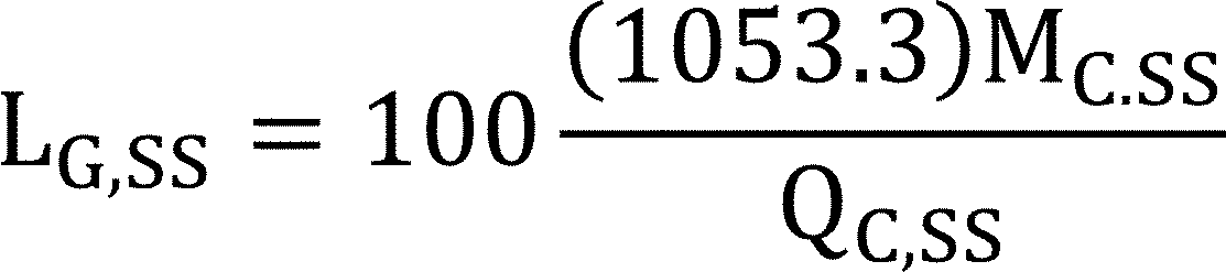
where:
100 = conversion factor to express a decimal as a percent,
1053.3 = latent heat of vaporization of water, Btu per pound,
Mc,ss = mass of condensate for the steady-state test as determined in section 3.8.1 of this appendix, pounds, and
Qc,ss = fuel energy input for steady-state test as determined in section 3.8.1 of this appendix, Btu.
4.1.6.2 Heat loss due to hot condensate going down the drain under steady-state conditions. Calculate the steady-state heat loss due to hot condensate going down the drain (LC,SS) expressed as a percent and defined as:

where:
LG,SS = Latent heat gain due to condensation under steady-state conditions as defined in section 4.1.6.1 of this appendix,
1.0 = specific heat of water, Btu/lb− °F,
TF,SS = Flue (or stack) gas temperature as defined in section 3.1 of this appendix, °F,
70 = assumed indoor temperature, °F,
0.45 = specific heat of water vapor, Btu/lb− °F, and
45 = average outdoor temperature for vented heaters, °F.
4.1.6.3 Latent heat gain due to condensation under cyclic conditions. (only for vented heaters tested under the optional tracer gas procedures of section 3.3 or 3.6 of this appendix) Calculate the latent heat gain (LG) expressed as a percent and defined as:
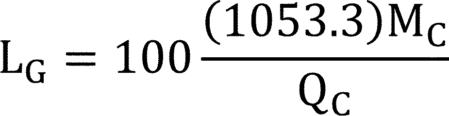
where:
100 = conversion factor to express a decimal as a percent,
1053.3 = latent heat of vaporization of water, Btu per pound,
Mc = mass of condensate for the cyclic test as determined in 3.8.2 of this appendix, pounds, and
Qc = fuel energy input for cyclic test as determined in 3.8.2 of this appendix, Btu.
4.1.6.4 Heat loss due to hot condensate going down the drain under cyclic conditions. (only for vented heaters tested under the optional tracer gas procedures of section 3.3 or 3.6 of this appendix) Calculate the cyclic heat loss due to hot condensate going down the drain (LC) expressed as a percent and defined as:
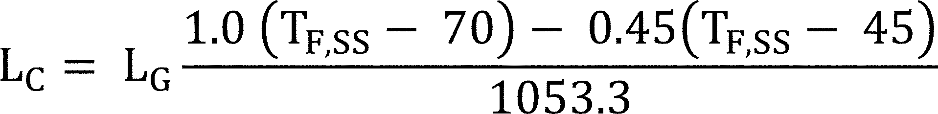
where:
LG = Latent heat gain due to condensation under cyclic conditions as defined in section 4.1.6.3 of this appendix,
1.0 = specific heat of water, Btu/lb− °F,
TF,SS = Flue (or stack) gas temperature as defined in section 3.1 of this appendix,
70 = assumed indoor temperature, °F,
0.45 = specific heat of water vapor, Btu/lb− °F, and
45 = average outdoor temperature for vented heaters, °F.
4.1.7 Ratio of combustion air mass flow rate to stoichiometric air mass flow rate. Determine the ratio of combustion air mass flow rate to stoichiometric air mass flow rate (RT,F), and defined as:
RT,F = A + B/XCO2F
where:
A = as determined from Table 2 of this appendix
B = as determined from Table 2 of this appendix
XCO2F = as defined in 3.1 of this appendix
4.1.8 Ratio of combustion and relief air mass flow rate to stoichiometric air mass flow rate. For vented heaters equipped with either an integral draft diverter or a draft hood, determine the ratio of combustion and relief air mass flow rate to stoichiometric air mass flow rate (RT,S), and defined as:
RT,S = A + [B/XCO2S]
where:
A = as determined from Table 2 of this appendix,
B = as determined from Table 2 of this appendix, and
XCO2S = as defined in section 3.1 of this appendix.
4.1.9 Sensible heat loss at steady-state operation. For vented heaters equipped with either an integral draft diverter or a draft hood, determine the sensible heat loss at steady-state operation (LS,SS,A) expressed as a percent and defined as:
where:
LS,SS,A = C(RT,S + D)(TS,SS−TRA)
C = as determined from Table 2 of this appendix
RT,S = as defined in 4.1.8 of this appendix
D = as determined from Table 2 of this appendix
TS,SS = as defined in 3.1 of this appendix
TRA = as defined in 2.9 of this appendix
For vented heaters equipped without an integral draft diverter, determine (LS,SS,A) expressed as a percent and defined as:
LS,SS,A = C(RT,F + D)(TF,SS−TRA)
where:
C = as determined from Table 2 of this appendix
RT,F = as defined in 4.1.7 of this appendix
D = as determined from Table 2 of this appendix
TF,SS = as defined in 3.1 of this appendix
TRA = as defined in 2.9 of this appendix
4.1.10 Steady-state efficiency. For vented heaters equipped with single-stage thermostats, calculate the steady-state efficiency (excluding jacket loss), ηSS, expressed in percent and defined as:
ηSS = 100−LL,A−LS,SS,A
where:
LL,A = latent heat loss, as defined in section 4.1.6 of this appendix (for condensing vented heaters LL,A* for steady-state conditions), and
LS,SS,A = sensible heat loss at steady-state operation, as defined in section 4.1.9 of this appendix.
For vented heaters equipped with either two stage controls or with step-modulating controls, calculate the steady-state efficiency at the reduced fuel input rate, ηSS−L, expressed in percent and defined as:
ηSS−L = 100−LL,A−LS,SS,A
where:
LL,A = latent heat loss, as defined in section 4.1.6 of this appendix (for condensing vented heaters LL,A* for steady-state conditions at the reduced firing rate), and
LS,SS,A = sensible heat loss at steady-state operation, as defined in section 4.1.9 of this appendix, in which LS,SS,A is determined at the reduced fuel input rate.
For vented heaters equipped with two stage controls, calculate the steady-state efficiency at the maximum fuel input rate, ηSS−H, expressed in percent and defined as:
ηSS−H = 100−LL,A−LS,SS,A
where:
LL,A = latent heat loss, as defined in section 4.1.6 of this appendix (for condensing vented heaters LL,A* for steady-state conditions at the maximum fuel input rate), and
LS,SS,A = sensible heat loss at steady-state operation, as defined in section 4.1.9 of this appendix, in which LS,SS,A is measured at the maximum fuel input rate.
For vented heaters equipped with step-modulating thermostats, calculate the weighted-average steady-state efficiency in the modulating mode, ηSS−MOD, expressed in percent and defined as:

where:
ηSS-H = steady-state efficiency at the maximum fuel input rate, as defined in section 4.1.10 of this appendix,
ηSS-L = steady-state efficiency at the reduced fuel input rate, as defined in section 4.1.10 of this appendix,
TOA* = average outdoor temperature for vented heaters with step-modulating thermostats operating in the modulating mode and is obtained from Table 3 or Figure 1 of this appendix, and
TC = balance point temperature which represents a temperature used to apportion the annual heating load between the reduced input cycling mode and either the modulating mode or maximum input cycling mode and is obtained either from Table 3 of this appendix or calculated by the following equation:
TC = 65−[(65−15)R]
where:
65 = average outdoor temperature at which a vented heater starts operating,
15 = national average outdoor design temperature for vented heaters, and
R = ratio of reduced to maximum heat output rates, as defined in section 4.1.13 of this appendix.
4.1.11 Reduced heat output rate. For vented heaters equipped with either two stage thermostats or step-modulating thermostats, calculate the reduced heat output rate
(Qred-out) defined as:
Qred-out = ηSS-L Qred-in
where:
ηSS-L = as defined in 4.1.10 of this appendix
Qred-in = the reduced fuel input rate
4.1.12 Maximum heat output rate. For vented heaters equipped with either two stage thermostats or step-modulating thermostats, calculate the maximum heat output rate (Qmax-out) defined as:
Qmax,out = hSS,H Qmax,in
where:
ηSS-H = as defined in 4.1.10 of this appendix
Qmax-in = the maximum fuel input rate
4.1.13 Ratio of reduced to maximum heat output rates. For vented heaters equipped with either two stage thermostats or step-modulating thermostats, calculate the ratio of reduced to maximum heat output rates (R) expressed as a decimal and defined as:
R = Qred-out/Qmax-out
where:
Qred-out = as defined in 4.1.11 of this appendix
Qmax-out = as defined in 4.1.12 of this appendix
4.1.14 Fraction of heating load at reduced operating mode. For vented heaters equipped with either two stage thermostats or step-modulating thermostats, determine the fraction of heating load at the reduced operating mode (X1) expressed as a decimal and listed in Table 3 of this appendix or obtained from Figure 2 of this appendix.
4.1.15 Fraction of heating load at maximum operating mode or noncycling mode. For vented heaters equipped with either two stage thermostats or step-modulating thermostats, determine the fraction of heating load at the maximum operating mode or noncycling mode (X2) expressed as a decimal and listed in Table 3 of this appendix or obtained from Figure 2 of this appendix.
4.1.16 Weighted-average steady-state efficiency. For vented heaters equipped with single-stage thermostats, the weighted-average steady-state efficiency (ηSS-WT) is equal to ηSS, as defined in section 4.1.10 of this appendix. For vented heaters equipped with two stage thermostats, ηSS-WT is defined as:
ηSS-WT = X1ηSS-L + X2ηSS-H
where:
X1 = as defined in section 4.1.14 of this appendix
ηSS-L = as defined in section 4.1.10 of this appendix
X2 = as defined in section 4.1.15 of this appendix
ηSS-H = as defined in section 4.1.10 of this appendix
For vented heaters equipped with step-modulating controls, ηSS-WT is defined as:
ηSS-WT = X1ηSS-L + X2ηSS-MOD
where:
X1 = as defined in section 4.1.14 of this appendix
ηSS-L = as defined in section 4.1.10 of this appendix
X2 = as defined in section 4.1.15 of this appendix
ηSS-MOD = as defined in section 4.1.10 of this appendix
4.1.17 Annual fuel utilization efficiency. Calculate the annual fuel utilization efficiency (AFUE) expressed as percent and defined as:
AFUE=[0.968ηSS − WT] − 1.78DF − 1.89DS − 129PF − 2.8 LJ + 1.81
where:
ηSS-WT = as defined in 4.1.16 of this appendix
DF = as defined in 4.1.2 of this appendix
DS = as defined in 4.1.3 of this appendix
PF = as defined in 4.1.4 of this appendix
LJ = as defined in 4.1.5 of this appendix
4.2 Annual fuel utilization efficiency for gas or oil fueled vented home heating equipment equipped with manual controls. The following procedure determines the annual fuel utilization efficiency for gas or oil fueled vented home heating equipment equipped with manual controls.
4.2.1 Average ratio of stack gas mass flow rate to flue gas mass flow rate at steady-state operation. For vented heaters equipped with either direct vents or direct exhaust or that are outdoor units, the average ratio of stack gas mass flow rate to flue gas mass flow rate at steady-state operation (S/F) shall be equal to unity. (S/F = 1) For all other types of vented heaters, calculate (S/F) defined as:

where:
RT,S = as defined in section 4.1.8 of this appendix with XCO2s as measured in section 3.1. of this appendix
RT,F = as defined in section 4.1.7 of this appendix with XCO2F as measured in section 3.1. of this appendix
4.2.2 Multiplication factor for infiltration loss during burner on-cycle. Calculate the multiplication factor for infiltration loss during burner on-cycle (KI,ON) defined as:
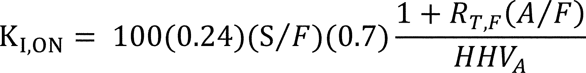
where:
100 = converts a decimal fraction into a percent
0.24 = specific heat of air
A/F = stoichiometric air/fuel ratio, determined in accordance with Table 2 of this appendix
S/F = as defined in section 4.2.1 of this appendix
0.7 = infiltration parameter
RT,F = as defined in section 4.1.7 of this appendix
HHVA = average higher heating value of the test fuel, determined in accordance with Table 2 of this appendix
4.2.3 On-cycle infiltration heat loss. Calculate the on-cycle infiltration heat loss (LI,ON) expressed as a percent and defined as:
LI,ON = KI,ON (70-45)
where:
KI,ON = as defined in 4.2.2 of this appendix
70 = average indoor temperature
45 = average outdoor temperature
4.2.4 Weighted-average steady-state efficiency.
4.2.4.1 For manually controlled heaters with various input rates the weighted average steady-state efficiency (ηSS−WT), is determined as follows:
ηSS-WT = 100−LL,A−LS,SS,A
where:
LL,A = latent heat loss, as defined in section 4.1.6 of this appendix (for condensing vented heaters, LL,A* for steady-state conditions), and
LS,SS,A = steady-state efficiency at the reduced fuel input rate, as defined in section 4.1.9 of this appendix and where LL,A and LS,SS,A are determined:
(1) at 50 percent of the maximum fuel input rate as measured in either section 3.1.1 of this appendix for manually controlled gas vented heaters or section 3.1.2 of this appendix for manually controlled oil vented heaters, or
(2) at the minimum fuel input rate as measured in either section 3.1.1 of this appendix for manually controlled gas vented heaters or section 3.1.2 of this appendix for manually controlled oil vented heaters if the design of the heater is such that the ±5 percent of 50 percent of the maximum fuel input rate cannot be set, provided this minimum rate is no greater than 2⁄3 of the maximum input rate of the heater.
4.2.4.2 For manually controlled heater with one single firing rate the weighted average steady-state efficiency is the steady-state efficiency measured at the single firing rate.
4.2.5 Part-load fuel utilization efficiency. Calculate the part-load fuel utilization efficiency (ηu) expressed as a percent and defined as:
ηu = ηSS-WT−LI,ON
where:
ηSS-WT = as defined in 4.2.4 of this appendix
LI,ON = as defined in 4.2.3 of this appendix
4.2.6 Annual Fuel Utilization Efficiency.
4.2.6.1 For manually controlled vented heaters, calculate the AFUE expressed as a percent and defined as:

where:
2,950 = average number of heating degree days
ηSS = as defined as ηSS−WT in 4.2.4 of this appendix
ηu = as defined in 4.2.5 of this appendix
Qin−max = as defined as Qin at the maximum fuel input rate, as defined in 3.1 of this appendix
4,600 = average number of non-heating season hours per year
QP = as defined in 3.5 of this appendix
2.083 = (65 − 15) / 24 = 50 / 24
65 = degree day base temperature, °F
15 = national average outdoor design temperature for vented heaters as defined in section 4.1.10 of this appendix
24 = number of hours in a day
4.2.6.2 For manually controlled vented heaters where the pilot light can be turned off by the user when the heater is not in use as described in section 3.5.2, calculate the AFUE expressed as a percent and defined as:
AFUE=ηu
where:
ηu = as defined in section 4.2.5 of this appendix
4.3 Annual fuel utilization efficiency by the tracer gas method. The annual fuel utilization efficiency shall be determined by the following tracer gas method for all vented heaters equipped with thermal stack dampers.
4.3.1 On-cycle sensible heat loss. For vented heaters equipped with single-stage thermostats, calculate the on-cycle sensible heat loss (LS,ON) expressed as a percent and defined as:
LS,ON = LS,SS,A
where:
LS,SS,A = as defined in section 4.1.9 of this appendix
For vented heaters equipped with two stage thermostats, calculate LS,ON defined as:
LS,ON = X1LS,SS,A-red + X2LS,SS,A-max
where:
X1 = as defined in section 4.1.14 of this appendix
LS,SS,A-red = as defined as LS,SS,A in section 4.1.9 of this appendix at the reduced fuel input rate
X2 = as defined in section 4.1.15 of this appendix
LS,SS,A-max = as defined as LS,SS,A in section 4.1.9 of this appendix at the maximum fuel input rate
For vented heaters with step-modulating controls, calculate LS,ON defined as:
LS,ON = X1LS,SS,A-red + X2LS,SS,A-avg
where:
X1 = as defined in section 4.1.14 of this appendix
LLS,SS,A-red = as defined in section 4.3.1 of this appendix
X2 = as defined in section 4.1.15 of this appendix
LS,SS,A-avg = average sensible heat loss for step-modulating vented heaters operating in the modulating mode
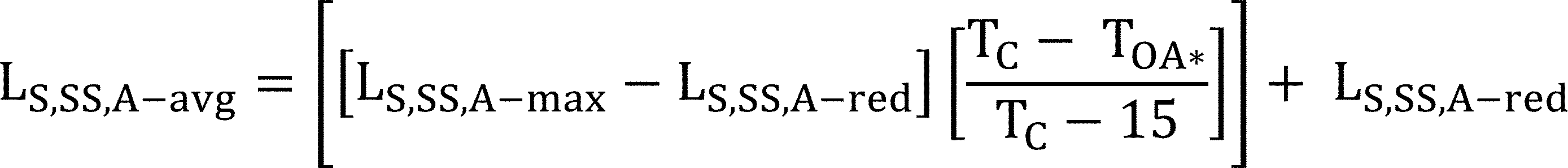
where:
LS,SS,A-avg = as defined in section 4.3.1 of this appendix
TC = as defined in section 4.1.10 of this appendix
TOA* = as defined in section 4.1.10 of this appendix
15 = as defined in section 4.1.10 of this appendix
4.3.2 On-cycle infiltration heat loss. For vented heaters equipped with single-stage thermostats, calculate the on-cycle infiltration heat loss (LI,ON) expressed as a percent and defined as:
LI,ON = KI,ON(70−45)
where:
KI,ON = as defined in section 4.2.2 of this appendix
70 = as defined in section 4.2.3 of this appendix
45 = as defined in section 4.2.3 of this appendix
For vented heaters equipped with two stage thermostats, calculate LI,ON defined as:
LI,ON = X1KI,ON-Max(70−TOA*) + X2KI,ON,red(70−TOA)
where:
X1 = as defined in section 4.1.14 of this appendix
KI,ON-max = as defined as KI,ON in section 4.2.2 of this appendix at the maximum heat input rate
70 = as defined in section 4.2.3 of this appendix
TOA* = as defined in section 4.3.4 of this appendix
KI,ON,red = as defined as KI,ON in section 4.2.2 of this appendix at the minimum heat input rate
TOA = as defined in section 4.3.4 of this appendix
X2 = as defined in section 4.1.15 of this appendix
For vented heaters equipped with step-modulating thermostats, calculate LI,ON defined as:
LI,ON = X1KI,ON-avg(70−TOA*) + X2KI,ON,red(70−TOA)
where:
X1 = as defined in section 4.1.14 of this appendix

70 = as defined in section 4.2.3 of this appendix
TOA* = as defined in section 4.3.4 of this appendix
X2 = as defined in section 4.1.15 of this appendix
TOA = as defined in section 4.3.4 of this appendix
4.3.3 Off-cycle sensible heat loss. For vented heaters equipped with single-stage thermostats, calculate the off-cycle sensible heat loss (LS,OFF) at the maximum fuel input rate. For vented heaters equipped with step-modulating thermostats, calculate LS,OFF defined as:
LS,OFF = X1 LS,OFF,red
where:
X1 = as defined in section 4.1.14 of this appendix, and
LS,OFF,red = as defined as LS,OFF in section 4.3.3 of this appendix at the reduced fuel input rate.
For vented heaters equipped with two stage controls, calculate LS,OFF defined as:
LS,OFF = X1 LS,OFF,red + X2 LS,OFF,Max
where:
X1 = as defined in section 4.1.14 of this appendix,
LS,OFF,red = as defined as LS,OFF in section 4.3.3 of this appendix at the reduced fuel input rate,
X2 = as defined in section 4.1.15 of this appendix, and
LS,OFF,Max = as defined as LS,OFF in section 4.3.3 of this appendix at the maximum fuel input rate.
Calculate the off-cycle sensible heat loss (LS,OFF) expressed as a percent and defined as:
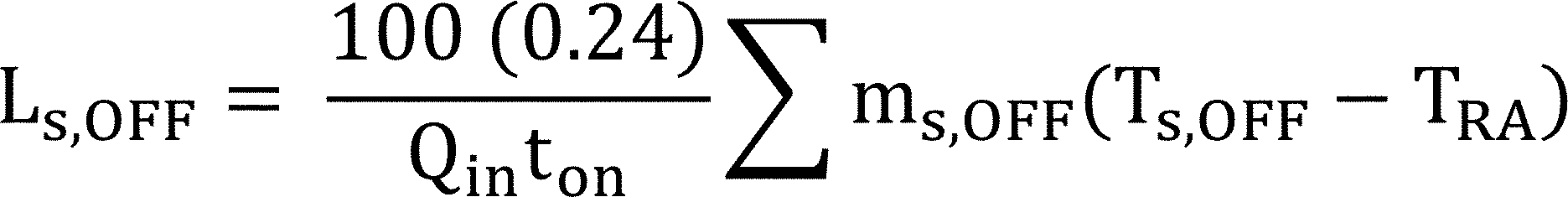
where:
100 = conversion factor for percent,
0.24 = specific heat of air in Btu per pound - °F,
Qin = fuel input rate, as defined in section 3.1 of this appendix in Btu per minute (as appropriate for the firing rate),
ton = average burner on-time per cycle and is 20 minutes,
Σ mS,OFF (TS,OFF −TRA) = summation of the ten values (for single-stage or step-modulating models) or twenty values (for two tage models) of the quantity, mS,OFF (TS,OFF −TRA), measured in accordance with section 3.3 of this appendix, and
mS,OFF = stack gas mass flow rate pounds per minute.
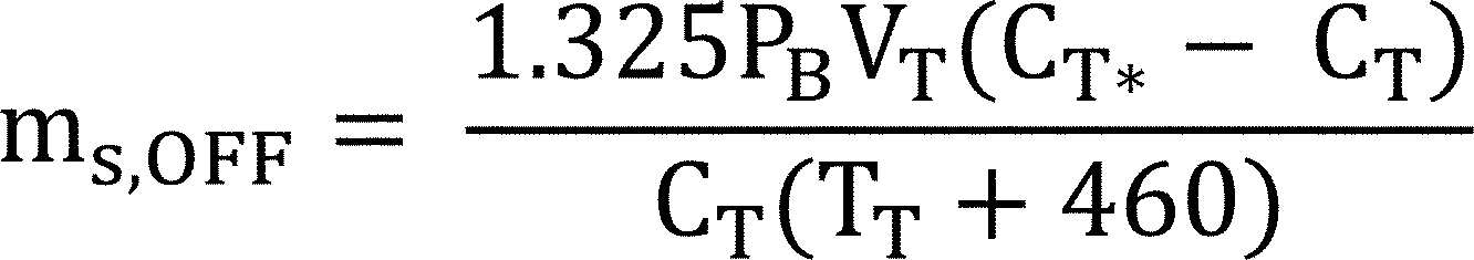
TS,OFF = stack gas temperature measured in accordance with section 3.3 of this appendix,
TRA = average room temperature measured in accordance with section 3.3 of this appendix,
PB = barometric pressure in inches of mercury,
VT = flow rate of the tracer gas through the stack in cubic feet per minute,
CT* = concentration by volume of the active tracer gas in the mixture in percent and is 100 when the tracer gas is a single component gas,
CT = concentration by volume of the active tracer gas in the diluted stack gas in percent,
TT = temperature of the tracer gas entering the flow meter in degrees Fahrenheit, and
(TT + 460) = absolute temperature of the tracer gas entering the flow meter in degrees Rankine.
4.3.4 Average outdoor temperature. For vented heaters equipped with single-stage thermostats, the average outdoor temperature (TOA) is 45 °F. For vented heaters equipped with either two stage thermostats or step-modulating thermostats, TOA during the reduced operating mode is obtained from Table 3 or Figure 1 of this appendix. For vented heaters equipped with two stage thermostats, TOA* during the maximum operating mode is obtained from Table 3 or Figure 1 of this appendix.
4.3.5 Off-cycle infiltration heat loss. For vented heaters equipped with single stage thermostats, calculate the off-cycle infiltration heat loss (LI,OFF) at the maximum fuel input rate. For vented heaters equipped with step-modulating thermostats, calculate LI,OFF defined as:
LI,OFF = X1LI,OFF,red
where:
X1 = as defined in section 4.1.14 of this appendix
LI,OFF,red = as defined in LI,OFF in section 4.3.5 of this appendix at the reduced fuel input rate
For vented heaters equipped with two stage thermostats, calculate LI,OFF defined as:
LI,OFF = X1LI,OFF,red + X2LI,OFF,max
where:
X1 = as defined in section 4.1.14 of this appendix
LI,OFF,red = as defined as LI,OFF in section 4.3.5 of this appendix at the reduced fuel input rate
X2 = as defined in section 4.1.15 of this appendix
LI,OFF,Max = as defined as LI,OFF in section 4.3.5 of this appendix at the maximum fuel input rate
Calculate the off-cycle infiltration heat loss (LI,OFF) expressed as a percent and defined as:

where:
100 = conversion factor for percent
0.24 = specific heat of air in Btu per pound - °F
1.3 = dimensionless factor for converting laboratory measured stack flow to typical field conditions
0.7 = infiltration parameter
70 = assumed average indoor air temperature, °F
TOA = average outdoor temperature as defined in section 4.3.4 of this appendix
Qin = fuel input rate, as defined in section 3.1 of this appendix in Btu per minute (as appropriate for the firing rate)
ton = average burner on-time per cycle and is 20 minutes
Σ mS,OFF = summation of the twenty values of the quantity, mS,OFF, measured in accordance with section 3.3 of this appendix
mS,OFF = as defined in section 4.3.3 of this appendix
4.3.6 Part-load fuel utilization efficiency. Calculate the part-load fuel utilization efficiency (ηu) expressed as a percent and defined as:

where:
Cj = 2.8, adjustment factor,
Lj = jacket loss as defined in section 4.1.5,
LL,A = Latent heat loss, as defined in section 4.1.6 of this appendix (for condensing vented heaters LL,A* for cyclic conditions),
ton = Average burner on time which is 20 minutes,
LS,ON = On-cycle sensible heat loss, as defined in section 4.3.1 of this appendix,
LS,OFF = Off-cycle sensible heat loss, as defined in section 4.3.3 of this appendix,
LI,ON = On-cycle infiltration heat loss, as defined in section 4.3.2 of this appendix,
LI,OFF = Off-cycle infiltration heat loss, as defined in section 4.3.5 of this appendix,
PF = Pilot fraction, as defined in section 4.1.4 of this appendix, and
tOFF = average burner off-time per cycle, which is 20 minutes.
4.3.7 Annual Fuel Utilization Efficiency.
Calculate the AFUE expressed as a percent and defined as:

where:
2,950 = average number of heating degree days
ηSS-WT = as defined in 4.1.16 of this appendix
ηu = as defined in 4.3.6 of this appendix
Qin−max = as defined in 4.2.6 of this appendix
4,600 = as specified in 4.2.6 of this appendix
QP = as defined in 3.5 of this appendix
2.083 = as specified in 4.2.6 of this appendix
4.4 Stack damper effectiveness for vented heaters equipped with electro-mechanical stack dampers. Determine the stack damper effectiveness for vented heaters equipped with electro-mechanical stack dampers (Do), defined as:
Do = 1.62 [1 - AD cos Ω/AS]
where:
AD = as defined in 3.4 of this appendix
Ω = as defined in 3.4 of this appendix
AS = as defined in 3.4 of this appendix
4.5 Addition requirements for vented home heating equipment using indoor air for combustion and draft control. For vented home heating equipment using indoor air for combustion and draft control, DF, as described in section 4.1.2 of this appendix, and DS, as described in section 4.1.3 of this appendix, shall be determined from Table 1 of this appendix.
4.5.1 Optional procedure for determining DP for vented home heating equipment. Calculate the ratio (DP) of the rate of flue gas mass through the vented heater during the off-period, MF,OFF(TF,SS), to the rate of flue gas mass flow during the on-period, MF,SS(TF,SS), and defined as:
DP = MF,OFF(TF,SS)/MF,SS(TF,SS)
For vented heaters in which no draft is maintained during the steady-state or cool down tests, MF,OFF(TF,SS) is defined as:

For oil fueled vented heaters in which an imposed draft is maintained, as described in section 3.6 of this appendix, MF,OFF(TF,SS) is defined as:
MF,OFF(TF,SS) = MF,OFF(T*F,OFF)
where:
TF,SS = as defined in section 3.1.1 of this appendix,
T*F,OFF = flue gas temperature during the off-period measured in accordance with section 3.6 of this appendix in degrees Fahrenheit, and
TRA = as defined in section 2.9 of this appendix.
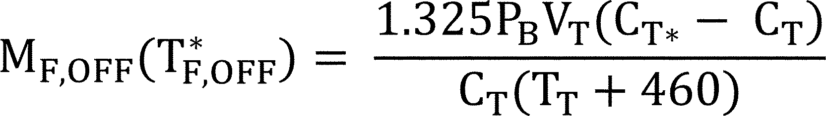
PB = barometric pressure measured in accordance with section 3.6 of this appendix in inches of mercury,
VT = flow rate of tracer gas through the vented heater measured in accordance with section 3.6 of this appendix in cubic feet per minute,
CT = concentration by volume of tracer gas present in the flue gas sample measured in accordance with section 3.6 of this appendix in percent,
CT* = concentration by volume of the active tracer gas in the mixture in percent and is 100 when the tracer gas is a single component gas,
TT = the temperature of the tracer gas entering the flow meter measured in accordance with section 3.6 of this appendix in degrees Fahrenheit, and
(TT + 460) = absolute temperature of the tracer gas entering the flow meter in degrees Rankine.
MF,SS(TF,SS) = Qin[RT,F(A/F) + 1]/[60HHVA]
Qin = as defined in section 3.1 of this appendix,
RT,F = as defined in section 4.1.7 of this appendix,
A/F = as defined in section 4.2.2 of this appendix, and
HHVA = as defined in section 4.2.2 of this appendix.
4.5.2 Optional procedure for determining off-cycle draft factor for flue gas flow for vented heaters. For systems numbered 1 through 10, calculate the off-cycle draft factor for flue gas flow (DF) defined as:
DF = DP
For systems numbered 11 or 12: DF = DP DO
For systems complying with section 3.6.1 or 3.6.2, DF = 0.05
Where:
DP = as defined in section 4.5.1. of this appendix, and
DO = as defined in section 4.4 of this appendix.
4.5.3 Optional procedure for determining off-cycle draft factor for stack gas flow for vented heaters. Calculate the off-cycle draft factor for stack gas flow (DS) defined as:
For systems numbered 1 or 2: DS = 1.0
For systems numbered 3 or 4: DS = (DP + 0.79)/1.4
For systems numbered 5 or 6: DS = DO
For systems numbered 7 or 8 and if DO(S/F)<1:DS = DO DP
For systems numbered 7 or 8 and if DO(S/F)>1:
DS = DO DP + [0.85−DO DP] [DO(S/F)−1]/[S/F−1]
where:
DP = as defined in section 4.5.1 or 3.6.1 of this appendix, as applicable
DO = as defined in section 4.4 of this appendix
4.6 Annual energy consumption.
4.6.1 National average number of burner operating hours. For vented heaters equipped with single stage controls or manual controls, the national average number of burner operating hours (BOH) is defined as:
BOHSS = 1,416AFA DHR−1,416 B
where:
1,416 = national average heating load hours for vented heaters based on 2,950 degree days and 15 °F outdoor design temperature
AF = 0.7067, adjustment factor to adjust the calculated design heating requirement and heating load hours to the actual heating load experienced by the heating system
DHR = typical design heating requirements based on QOUT, from Table 4 of this appendix.
QOUT = [(ηSS/100)−Cj (Lj/100)] Qin
Lj = jacket loss as defined in 4.1.5 of this appendix
Cj = 2.8, adjustment factor as defined in 4.3.6 of this appendix
ηSS = steady-state efficiency as defined in 4.1.10 of this appendix, percent
Qin = as defined in 3.1 of this appendix at the maximum fuel input rate
A = 100,000/[341,300PE + (Qin−QP)ηu]
B = 2.938(QP) ηu A/100,000
100,000 = factor that accounts for percent and kBtu
PE = as defined in 3.1.3 of this appendix
QP = as defined in 3.5 of this appendix
ηu = as defined in 4.3.6 of this appendix for vented heaters using the tracer gas method, percent
= as defined in 4.2.5 of this appendix for manually controlled vented heaters, percent
= 2,950 AFUEηSS Qin/[2,950 ηSS Qin - AFUE(2.083)(4,600)QP], for vented heaters equipped without manual controls and without thermal stack dampers and not using the optional tracer gas method, where:
AFUE = as defined in 4.1.17 of this appendix, percent
2,950 = average number of heating degree days as defined in 4.2.6 of this appendix
4,600 = average number of non-heating season hours per year as defined in 4.2.6 of this appendix
2.938 = (4,160/1,416) = ratio of the average length of the heating season in hours to the average heating load hours
2.083 = as specified in 4.2.6 of this appendix
4.6.1.1 For vented heaters equipped with two stage or step modulating controls the national average number of burner operating hours at the reduced operating mode is defined as:
BOHR = X1EM/Qred-in
where:
X1 = as defined in 4.1.14 of this appendix
Qred-in = as defined in 4.1.11 of this appendix
EM = average annual energy used during the heating season
= (Qin−QP)BOHSS + (8,760−4,600)QP
Qin = as defined in 3.1 of this appendix at the maximum fuel input rate
QP = as defined in 3.5 of this appendix
BOHSS = as defined in 4.6.1 of this appendix, in which the term PE in the factor A is increased by the factor R, which is defined in 3.1.3 of this appendix as:
R = 1.3 for two stage controls
= 1.4 for step modulating controls when the ratio of minimum-to-maximum fuel input is greater than or equal to 0.7
= 1.7 for step modulating controls when the ratio of minimum-to-maximum fuel input is less than 0.7 and greater than or equal to 0.5
= 2.2 for step modulating controls when the ratio of minimum-to-maximum fuel input is less than 0.5
A = 100,000/[341,300 PE R + (Qin − QP)ηu]
8,760 = total number of hours per year
4,600 = as specified in 4.2.6 of this appendix
4.6.1.2 For vented heaters equipped with two stage or step modulating controls the national average number of burner operating hours at the maximum operating mode (BOHH) is defined as:
BOHH = X2EM/Qin
where:
X2 = as defined in 4.1.15 of this appendix
EM = average annual energy used during the heating season
= (Qin−QP)BOHSS + (8,760−4,600)QP
Qin = as defined in 3.1 of this appendix at the maximum fuel input rate
4.6.2 Average annual fuel energy for gas or oil fueled vented heaters. For vented heaters equipped with single stage controls or manual controls, the average annual fuel energy consumption (EF) is expressed in Btu per year and defined as:
EF = BOHSS (Qin−QP) + 8,760 QP
where:
BOHSS = as defined in 4.6.1 of this appendix
Qin = as defined in 3.1 of this appendix
QP = as defined in 3.5 of this appendix
8,760 = as specified in 4.6.1 of this appendix
4.6.2.1 For vented heaters equipped with either two stage or step modulating controls EF is defined as:
EF = EM + 4,600QP
where:
EM = as defined in 4.6.1.2 of this appendix
4,600 = as specified 4.2.6 of this appendix
QP = as defined in 3.5 of this appendix
4.6.3 Average annual auxiliary electrical energy consumption for vented heaters. For vented heaters with single-stage controls or manual controls, the average annual auxiliary electrical consumption (EAE) is expressed in kilowatt-hours and defined as:
EAE = BOHSSPE + ESO
Where:
BOHSS = as defined in 4.6.1 of this appendix
PE = as defined in 3.1.3 of this appendix
ESO = as defined in 4.7 of this appendix
4.6.3.1 For vented heaters with two-stage or modulating controls, EAE is defined as:
EAE = (BOHR + BOHH)PE + ESO
Where:
BOHR = as defined in 4.6.1 of this appendix
BOHH = as defined in 4.6.1 of this appendix
PE = as defined in 3.1.3 of this appendix
ESO = as defined in 4.7 of this appendix
4.6.4 Average annual energy consumption for vented heaters located in a different geographic region of the United States and in buildings with different design heating requirements.
4.6.4.1 Average annual fuel energy consumption for gas or oil fueled vented home heaters located in a different geographic region of the United States and in buildings with different design heating requirements. For gas or oil fueled vented heaters the average annual fuel energy consumption for a specific geographic region and a specific typical design heating requirement (EFR) is expressed in Btu per year and defined as:
EFR = (EF−8,760 QP)(HLH/1,416) + 8,760QP
where:
EF = as defined in 4.6.2 of this appendix
8,760 = as specified in 4.6.1 of this appendix
QP = as defined in 3.5 of this appendix
HLH = heating load hours for a specific geographic region determined from the heating load hour map in Figure 3 of this appendix
1,416 = as specified in 4.6.1 of this appendix
4.6.4.2 Average annual auxiliary electrical energy consumption for gas or oil fueled vented home heaters located in a different geographic region of the United States and in buildings with different design heating requirements. For gas or oil fueled vented home heaters the average annual auxiliary electrical energy consumption for a specific geographic region and a specific typical design heating requirement (EAER) is expressed in kilowatt-hours and defined as:
EAER = EAE HLH/1,416
where:
EAE = as defined in 4.6.3 of this appendix
HLH = as defined in 4.6.4.1 of this appendix
1,416 = as specified in 4.6.1 of this appendix
Table 1 - Off-Cycle Draft Factors for Flue Gas Flow (DF) and for Stack Gas Flow (DS) for Vented Home Heating Equipment Equipped Without Thermal Stack Dampers
| System number | (DF) | (DS) | Burner type | Venting system type1 |
|---|---|---|---|---|
| 1 | 1.0 | 1.0 | Atmospheric | Draft hood or diverter. |
| 2 | 0.4 | 1.0 | Power | Draft hood or diverter. |
| 3 | 1.0 | 1.0 | Atmospheric | Barometric draft regulator. |
| 4 | 0.4 | 0.85 | Power | Barometric draft regulator. |
| 5 | 1.0 | DO | Atmospheric | Draft hood or diverter with damper. |
| 6 | 0.4 | DO | Power | Draft hood or diverter with damper. |
| 7 | 1.0 | DO | Atmospheric | Barometric draft regulator with damper. |
| 8 | 0.4 | DODP | Power | Barometric draft regulator with damper. |
| 9 | 1.0 | 0 | Atmospheric | Direct vent. |
| 10 | 0.4 | 0 | Power | Direct vent. |
| 11 | DO | 0 | Atmospheric | Direct vent with damper. |
| 12 | 0.4 DO | 0 | Power | Direct vent with damper. |
Table 2 - Values of Higher Heating Value (HHV(A), Stoichiometric Air/Fuel (A/F), Latent Heat Loss (LL,A) and Fuel-Specified Parameters (A, B, C, and D) for Typical Fuels
| Fuels | HHVA (Btu/lb) | A/F | LL,A | A | B | C | D |
|---|---|---|---|---|---|---|---|
| No. 1 oil | 19,800 | 14.56 | 6.55 | 0.0679 | 14.22 | 0.0179 | 0.167 |
| No. 2 oil | 19,500 | 14.49 | 6.50 | 0.0667 | 14.34 | 0.0181 | 0.167 |
| Natural gas | 20,120 | 14.45 | 9.55 | 0.0919 | 10.96 | 0.0175 | 0.171 |
| Manufactured gas | 18,500 | 11.81 | 10.14 | 0.0965 | 10.10 | 0.0155 | 0.235 |
| Propane | 21,500 | 15.58 | 7.99 | 0.0841 | 12.60 | 0.0177 | 0.151 |
| Butane | 20,000 | 15.36 | 7.79 | 0.0808 | 12.93 | 0.0180 | 0.143 |
Table 3 - Fraction of Heating Load at Reduced Operating Mode (X1) and at Maximum Operating Mode (X2), Average Outdoor Temperatures (TOA and TOA*), and Balance Point Temperature (TC) for Vented Heaters Equipped With Either Two-Stage Thermostats or Step-Modulating Thermostats
| Heat output ratioa | X1 | X2 | TOA | TOA* | TC |
|---|---|---|---|---|---|
| 0.20 to 0.24 | .12 | .88 | 57 | 40 | 53 |
| 0.25 to 0.29 | .16 | .84 | 56 | 39 | 51 |
| 0.30 to 0.34 | .20 | .80 | 54 | 38 | 49 |
| 0.35 to 0.39 | .30 | .70 | 53 | 36 | 46 |
| 0.40 to 0.44 | .36 | .64 | 52 | 35 | 44 |
| 0.45 to 0.49 | .43 | .57 | 51 | 34 | 42 |
| 0.50 to 0.54 | .52 | .48 | 50 | 32 | 39 |
| 0.55 to 0.59 | .60 | .40 | 49 | 30 | 37 |
| 0.60 to 0.64 | .70 | .30 | 48 | 29 | 34 |
| 0.65 to 0.69 | .76 | .24 | 47 | 27 | 32 |
| 0.70 to 0.74 | .84 | .16 | 46 | 25 | 29 |
| 0.75 to 0.79 | .88 | .12 | 46 | 22 | 27 |
| 0.80 to 0.84 | .94 | .06 | 45 | 20 | 23 |
| 0.85 to 0.89 | .96 | .04 | 45 | 18 | 21 |
| 0.90 to 0.94 | .98 | .02 | 44 | 16 | 19 |
| 0.95 to 0.99 | .99 | .01 | 44 | 13 | 17 |
Table 4 - Average Design Heating Requirements for Vented Heaters With Different Output Capacities
| Vented heaters output capacity Qout - (Btu/hr) | Average design heating requirements (kBtu/hr) |
|---|---|
| 5,000-7,499 | 5.0 |
| 7,500-10,499 | 7.5 |
| 10,500-13,499 | 10.0 |
| 13,500-16,499 | 12.5 |
| 16,500-19,499 | 15.0 |
| 19,500-22,499 | 17.5 |
| 22,500-26,499 | 20.5 |
| 26,500-30,499 | 23.5 |
| 30,500-34,499 | 26.5 |
| 34,500-38,499 | 30.0 |
| 38,500-42,499 | 33.5 |
| 42,500-46,499 | 36.5 |
| 46,500-51,499 | 40.0 |
| 51,500-56,499 | 44.0 |
| 56,500-61,499 | 48.0 |
| 61,500-66,499 | 52.0 |
| 66,500-71,499 | 56.0 |
| 71,500-76,500 | 60.0 |
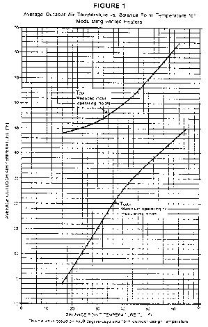


4.7 Average annual electric standby mode and off mode energy consumption.
Calculate the annual electric standby mode and off mode energy consumption, ESO, defined as, in kilowatt-hours:
ESO = ((PW,SB * (4160 - BOH)) + (PW,OFF * 4600)) * K
Where:
PW,SB = vented heater standby mode power, in watts, as measured in section 3.7 of this appendix
4160 = average heating season hours per year
PW,OFF = vented heater off mode power, in watts, as measured in section 3.7 of this appendix
4600 = average non-heating season hours per year
K = 0.001 kWh/Wh, conversion factor for watt-hours to kilowatt-hours
BOH = burner operating hours as calculated in section 4.6.1 of this appendix where for single-stage controls or manual controls vented heaters BOH = BOHSS and for vented heaters equipped with two-stage or modulating controls BOH = (BOHR + BOHH).
[49 FR 12169, Mar. 28, 1984, as amended at 62 FR 26162, May 12, 1997; 77 FR 74571, Dec. 17, 2012; 80 FR 806, Jan. 6, 2015]
Appendix P to Subpart B of Part 430—Uniform Test Method for Measuring the Energy Consumption of Pool Heaters
On and after July 6, 2015, any representations made with respect to the energy use or efficiency of all pool heaters must be made in accordance with the results of testing pursuant to this appendix. On and after this date, if a manufacturer makes representations of standby mode and off mode energy consumption, then testing must also include the provisions of this appendix related to standby mode and off mode energy consumption. Until July 6, 2015, manufacturers must test gas-fired pool heaters in accordance with this appendix, or appendix P as it appeared at 10 CFR part 430, subpart B revised as of January 1, 2014. Any representations made with respect to the energy use or efficiency of such pool heaters must be in accordance with whichever version is selected. DOE notes that, because testing under this appendix P must be completed as of July 6, 2015, manufacturers may wish to begin using this test procedure immediately.
1. Definitions.
1.1 Active mode means the condition during the pool heating season in which the pool heater is connected to the power source, and the main burner, electric resistance element, or heat pump is activated to heat pool water.
1.2 Coefficient of performance (COP ), as applied to heat pump pool heaters, means the ratio of heat output in kW to the total power input in kW.
1.3 Electric heat pump pool heater means an appliance designed for heating nonpotable water and employing a compressor, water-cooled condenser, and outdoor air coil.
1.4 Electric resistance pool heater means an appliance designed for heating nonpotable water and employing electric resistance heating elements.
1.5 Fossil fuel-fired pool heater means an appliance designed for heating nonpotable water and employing natural gas or oil burners.
1.6 Hybrid pool heater means an appliance designed for heating nonpotable water and employing both a heat pump (compressor, water-cooled condenser, and outdoor air coil) and a fossil fueled burner as heating sources.
1.7 Off mode means the condition during the pool non-heating season in which the pool heater is connected to the power source, and neither the main burner, nor the electric resistance elements, nor the heat pump is activated, and the seasonal off switch, if present, is in the “off” position.
1.8 Seasonal off switch means a switch that results in different energy consumption in off mode as compared to standby mode.
1.9 Standby mode means the condition during the pool heating season in which the pool heater is connected to the power source, and neither the main burner, nor the electric resistance elements, nor the heat pump is activated.
2. Test method.
2.1 Active mode.
2.1.1 Fossil fuel-fired pool heaters. The test method for testing fossil fuel-fired pool heaters in active mode is as specified in section 2.10 of ANSI Z21.56 (incorporated by reference, see § 430.3), with the following additional clarifications.
1. Burner input rate is adjusted as specified in section 2.3.3 of ANSI Z21.56,
2. Equilibrium is defined as in section 9.1.3 of ASHRAE 146 (incorporated by reference; see § 430.3)
3. Units are only to be tested using a recirculating loop and a pump if: the use of the recirculating loop and pump are listed as required; a minimum flow rate is specified in the installation or operation manual provided with the unit; the pump is packaged with the unit by the manufacturer; or such use is required for testing.
4. A water temperature rise of less than 40 °F is allowed only as specified in the installation or operation manual(s) provided with the unit.
2.1.2 Electric resistance pool heaters. The test method for testing electric resistance pool heaters in active mode is as specified in ASHRAE 146 (incorporated by reference; see § 430.3).
2.1.3 Electric heat pump pool heaters. The test method for testing electric heat pump pool heaters in active mode is as specified in AHRI 1160 (incorporated by reference; see § 430.3), which references ASHRAE 146 (incorporated by reference; see § 430.3).
2.1.4 Hybrid pool heaters. [Reserved]
2.2 Standby mode. The test method for testing the energy consumption of pool heaters in standby mode is as described in sections 3 through 5 of this appendix.
2.3 Off mode.
2.3.1 Pool heaters with a seasonal off switch. For pool heaters with a seasonal off switch, no off mode test is required.
2.3.2 Pool heaters without a seasonal off switch. For pool heaters without a seasonal off switch, the test method for testing the energy consumption of the pool heater is as described in sections 3 through 5 of this appendix.
3. Test conditions.
3.1 Active mode.
3.1.1 Fossil fuel-fired pool heaters. Establish the test conditions specified in section 2.10 of ANSI Z21.56 (incorporated by reference; see § 430.3).
3.1.2 Electric resistance pool heaters. Establish the test conditions specified in section 9.1.4 of ASHRAE 146 (incorporated by reference; see § 430.3).
3.1.3 Electric heat pump pool heaters. Establish the test conditions specified in section 5 of AHRI 1160. The air temperature surrounding the unit shall be at the “High Air Temperature—Mid Humidity (63% RH)” level specified in section 6 of AHRI 1160 (incorporated by reference, see § 430.3) (80.6 °F [27.0 °C] Dry-Bulb, 71.2 °F [21.8 °C]).
3.1.4 Hybrid pool heaters. [Reserved]
3.2 Standby mode and off mode. After completing the active mode tests described in sections 3.1 and 4.1 of this appendix, reduce the thermostat setting to a low enough temperature to put the pool heater into standby mode. Reapply the energy sources and operate the pool heater in standby mode for 60 minutes.
4. Measurements
4.1 Active mode
4.1.1 Fossil fuel-fired pool heaters. Measure the quantities delineated in section 2.10 of ANSI Z21.56 (incorporated by reference; see § 430.3). The measurement of energy consumption for oil-fired pool heaters in Btu is to be carried out in appropriate units (e.g., gallons).
4.1.2 Electric resistance pool heaters. Measure the quantities delineated in section 9.1.4 of ASHRAE 146 (incorporated by reference; see § 430.3) during and at the end of the 30-minute period when water is flowing through the pool heater.
4.1.3 Electric heat pump pool heaters. Measure the quantities delineated in section 9.1.1 and Table 2 of ASHRAE 146 (incorporated by reference; see § 430.3). Record the elapsed time, tHP, from the start of electric power metering to the end, in minutes.
4.1.4 Hybrid pool heaters. [Reserved]
4.2 Standby mode. For all pool heaters, record the average electric power consumption during the standby mode test, PW,SB, in W, in accordance with section 5 of IEC 62301 (incorporated by reference; see § 430.3). For fossil fuel-fired pool heaters, record the fossil fuel energy consumption during the standby test, Qp, in Btu. (Milli-volt electrical consumption need not be considered in units so equipped.) Ambient temperature and voltage specifications in section 4.1 of this appendix shall apply to this standby mode testing. Round the recorded standby power (PW,SB) to the second decimal place, and for loads greater than or equal to 10 W, record at least three significant figures.
4.3 Off mode.
4.3.1 Pool heaters with a seasonal off switch. For pool heaters with a seasonal off switch, the average electric power consumption during the off mode, PW,OFF = 0, and the fossil fuel energy consumed during the off mode, Qoff = 0.
4.3.2 Pool heaters without a seasonal off switch. For all pool heaters without a seasonal off switch, record the average electric power consumption during the standby/off mode test, PW,OFF = PW,SB, in W, in accordance with section 5 of IEC 62301 (incorporated by reference; see § 430.3). For fossil fuel-fired pool heaters without a seasonal off switch, record the fossil fuel energy consumption during the off mode test, Qoff (= Qp), in Btu. (Milli-volt electrical consumption need not be considered in units so equipped.) Ambient temperature and voltage specifications in section 4.1 of this appendix shall apply to this off mode testing. Round the recorded off mode power (PW,OFF) to the second decimal place, and for loads greater than or equal to 10 W, record at least three significant figures.
5. Calculations.
5.1 Thermal efficiency.
5.1.1 Fossil fuel-fired pool heaters. Calculate the thermal efficiency, Et (expressed as a percent), as specified in section 2.10 of ANSI Z21.56 (incorporated by reference; see § 430.3). The expression of fuel consumption for oil-fired pool heaters shall be in Btu.
5.1.2 Electric resistance pool heaters. Calculate the thermal efficiency, Et (expressed as a percent), as specified in section 11.1 of ASHRAE 146 (incorporated by reference; see § 430.3).
5.1.3 Electric heat pump pool heaters. Calculate the COP according to section 11.1 of ASHRAE 146. Calculate the thermal efficiency, Et (expressed as a percent): Et = COP.
5.1.4 Hybrid pool heaters. [Reserved]
5.2 Average annual fossil fuel energy for pool heaters. For electric resistance and electric heat pump pool heaters, the average annual fuel energy for pool heaters, EF = 0.
For fossil fuel-fired pool heaters, the average annual fuel energy for pool heaters, EF, is defined as:
EF = BOH QIN + (POH−BOH)QPR + (8760 − POH) Qoff,R
Where:
BOH = average number of burner operating hours = 104 h,
POH = average number of pool operating hours = 4,464 h,
QIN = rated fuel energy input as defined according to section 2.10.1 or section 2.10.2 of ANSI, Z21.56 (incorporated by reference; see § 430.3), as appropriate. (For electric resistance and electric heat pump pool heaters, QIN = 0.),
QPR = average energy consumption rate of continuously operating pilot light, if employed, = (QP/1 h),
QP = energy consumption of continuously operating pilot light, if employed, as measured in section 4.2 of this appendix, in Btu,
8760 = number of hours in one year,
Qoff,R = average off mode fossil fuel energy consumption rate = Qoff/(1 h), and
Qoff = off mode energy consumption as defined in section 4.3 of this appendix.
5.3 Average annual electrical energy consumption for pool heaters. The average annual electrical energy consumption for pool heaters, EAE, is expressed in Btu and defined as:
(1) EAE = EAE,active + EAE,standby,off
(2) EAE,active = BOH * PE
(3) EAE,standby,off = (POH−BOH) PW,SB(Btu/h) + (8760−POH) PW,OFF(Btu/h)
where:
EAE,active = electrical consumption in the active mode,
EAE,standby,off = auxiliary electrical consumption in the standby mode and off mode,
PE = 2Ec, for fossil fuel-fired heaters tested according to section 2.10.1 of ANSI Z21.56 (incorporated by reference; see § 430.3) and for electric resistance pool heaters, in Btu/h,
= 3.412 PErated, for fossil fuel-fired heaters tested according to section 2.10.2 of ANSI Z21.56, in Btu/h,
= Ec,HP * (60/tHP), for electric heat pump pool heaters, in Btu/h.
Ec = electrical consumption in Btu per 30 min. This includes the electrical consumption (converted to Btus) of the pool heater and, if present, a recirculating pump during the 30-minute thermal efficiency test. The 30-minute thermal efficiency test is defined in section 2.10.1 of ANSI Z21.56 for fossil fuel-fired pool heaters and section 9.1.4 of ASHRAE 146 (incorporated by reference; see § 430.3) for electric resistance pool heaters.
2 = conversion factor to convert unit from per 30 min. to per h.
PErated = nameplate rating of auxiliary electrical equipment of heater, in Watts
Ec,HP = electrical consumption of the electric heat pump pool heater (converted to equivalent unit of Btu), including the electrical energy to the recirculating pump if used, during the thermal efficiency test, as defined in section 9.1 of ASHRAE 146, in Btu.
tHP = elapsed time of data recording during the thermal efficiency test on electric heat pump pool heater, as defined in section 9.1 of ASHRAE 146, in minutes.
BOH = as defined in section 5.2 of this appendix,
POH = as defined in section 5.2 of this appendix,
PW,SB (Btu/h) = electrical energy consumption rate during standby mode expressed in Btu/h = 3.412 PW,SB, Btu/h,
PW,SB = as defined in section 4.2 of this appendix,
PW,OFF (Btu/h) = electrical energy consumption rate during off mode expressed in Btu/h = 3.412 PW,OFF, Btu/h, and
PW,OFF = as defined in section 4.3 of this appendix.
5.4 Integrated thermal efficiency.
5.4.1 Calculate the seasonal useful output of the pool heater as:
EOUT = BOH[(Et/100)(QIN + PE)]
where:
BOH = as defined in section 5.2 of this appendix,
Et = thermal efficiency as defined in section 5.1 of this appendix,
QIN = as defined in section 5.2 of this appendix,
PE = as defined in section 5.3 of this appendix, and
100 = conversion factor, from percent to fraction.
5.4.2 Calculate the annual input to the pool heater as:
EIN = EF + EAE
where:
EF = as defined in section 5.2 of this appendix, and
EAE = as defined in section 5.3 of this appendix.
5.4.3 Calculate the pool heater integrated thermal efficiency (TEI) (in percent).
TEI = 100(EOUT/EIN)
where:
EOUT = as defined in section 5.4.1 of this appendix,
EIN = as defined in section 5.4.2 of this appendix, and
100 = conversion factor, from fraction to percent.
[80 FR 813, Jan. 6, 2015]
Appendix Q to Subpart B of Part 430—Uniform Test Method for Measuring the Energy Consumption of Fluorescent Lamp Ballasts
Note regarding effective date: After October 14, 2020 and prior to March 15, 2021 any representations with respect to energy use or efficiency of fluorescent lamp ballasts must be in accordance with the results of testing pursuant to this appendix or the test procedures as they appeared in appendix Q to this subpart revised as of January 1, 2020. On or after March 15, 2021, any representations, including certifications of compliance for ballasts subject to any energy conservation standard, made with respect to the energy use or efficiency of fluorescent lamp ballasts must be made in accordance with the results of testing pursuant to this appendix.
0. Incorporation by Reference
DOE incorporated by reference ANSI C78.81-2016, ANSI C78.375A, ANSI C78.901-2016, ANSI C82.1, ANSI 82.2, ANSI 82.3, ANSI 82.11, ANSI C82.13, ANSI 82.77, IEC 60081, and IEC 62301, each in their entirety in § 430.3; however, only enumerated provisions of ANSI C78.375A, ANSI C82.2, and IEC 62301 are applicable to this appendix, as follows:
(a) ANSI C78.375A, as follows:
(i) Section 4, Ambient conditions for temperature measurement, as specified in section 2.4.2 of this appendix; and
(ii) Section 9, Electrical instruments, as specified in sections 2.2.1, 2.2.2, and 2.2.3 of this appendix.
(b) ANSI C82.2, as follows:
(i) Section 3, Pertinent measurements, as specified in section 2.4.1 of this appendix;
(ii) Section 4, Electrical supply characteristics—test ballast measurement circuits, as specified in section 2.4.1 of this appendix; and
(iii) Section 7, Test measurements circuits, as specified in sections 2.5.6, 2.5.7, and 2.5.8 of this appendix.
(c) IEC 62301 as follows:
(i) Section 5, Measurements, as specified in sections 3.4.3 and 3.4.4 of this appendix.
1. Definitions
1.1. Average total lamp arc power means the sample mean of the total lamp arc power of the ballast units tested.
1.2. Dimming ballast means a ballast that is designed and marketed to vary its output and that can achieve an output less than or equal to 50 percent of its maximum electrical output.
1.3. High frequency ballast is as defined in ANSI C82.13 (incorporated by reference; see § 430.3).
1.4. Instant-start is the starting method used in instant-start systems as defined in ANSI C82.13, as typically indicated on publicly available documents of a fluorescent lamp ballast (e.g., product literature, catalogs, and packaging labels).
1.5. Low-frequency ballast is a fluorescent lamp ballast that operates at a supply frequency of 50 to 60 Hz and operates the lamp at the same frequency as the supply.
1.6. Programmed-start is the starting method used in a programmed-start system as defined in ANSI C82.13, as typically indicated on publicly available documents of a fluorescent lamp ballast (e.g., product literature, catalogs, and packaging labels).
1.7. Rapid-start is the starting method used in rapid-start type systems as defined in ANSI C82.13, as typically indicated on publicly available documents of a fluorescent lamp ballast (e.g., product literature, catalogs, and packaging labels).
1.8. Reference lamp is a fluorescent lamp that meets the operating conditions of a reference lamp as defined by ANSI C82.13.
1.9. Residential ballast means a fluorescent lamp ballast that meets Federal Communications Commission (FCC) consumer limits as set forth in 47 CFR part 18 and is designed and marketed for use only in residential applications.
1.10. RMS is the root mean square of a varying quantity.
1.11 Sign Ballast means a ballast that has an Underwriters Laboratories Inc. Type 2 rating and is designed and marketed for use only in outdoor signs.
2. Active Mode Procedure for Measuring BLE at Full Light Output
2.1. Where ANSI C82.2 (incorporated by reference; see § 430.3) references ANSI C82.1, use ANSI C82.1 (incorporated by reference; see § 430.3) for testing low-frequency ballasts and use ANSI C82.11 (incorporated by reference; see § 430.3) for testing high-frequency ballasts. In addition when applying ANSI C82.2, use the standards ANSI C78.375A, ANSI C78.81-2016, ANSI C82.1, ANSI C82.11, ANSI C82.13, ANSI C82.3, ANSI C82.77, and ANSI C78.901-2016 (incorporated by reference; see § 430.3) instead of the normative references in ANSI 82.2. Specifications in referenced standards that are recommended, that “shall” or “should” be met, or that are not clearly mandatory, are mandatory. In cases where there is a conflict between any industry standard(s) and this appendix, the language of the test procedure in this appendix takes precedence over the industry standard(s).
2.2. Instruments
2.2.1. All instruments must meet the specifications of section 9 of ANSI C78.375A.
2.2.2. Power Analyzer. In addition to the specifications in section 9 of ANSI C78.375A, the power analyzer must have a maximum 100 pF capacitance to ground and frequency response between 40 Hz and 1 MHz.
2.2.3. Current Probe. In addition to the specifications in section 9 of ANSI C78.375A, the current probe must be galvanically isolated and have frequency response between 40 Hz and 20 MHz.
2.3. Test Setup
2.3.1. Connect the ballast to a main power source and to the fluorescent lamp(s) as specified in this section. Ensure the ballast is connected to fluorescent lamp(s) according to any manufacturer's wiring instructions on or sold with each unit (including those provided online). To test a low-frequency ballast, follow ANSI C82.1 but disregard section 5.3 of ANSI C82.1. To test a high-frequency ballast, follow ANSI C82.11 but disregard sections 5.3.1 and 5.13 and Annex D of ANSI C82.11.
2.3.2. In the test setup, all wires used in the apparatus, including any wires from the ballast to the lamps and from the lamps to the measuring devices, must meet the following specifications:
2.3.2.1. Use the wires provided by the ballast manufacturer and only the minimum wire length necessary to reach both ends of each lamp. If the wire lengths supplied with the ballast are too short to reach both ends of each lamp, add the minimum additional wire length necessary to reach both ends of each lamp, using wire of the same wire gauge(s) as the wire supplied with the ballast. If no wiring is provided with the ballast, use 18 gauge or thicker wire.
2.3.2.2. Keep wires loose. Do not shorten or allow bundling of any wires. Separate all wires from each other, and ground them to prevent parasitic capacitance.
2.3.3. Test each ballast with only one fluorescent lamp type. Select the one type of fluorescent lamp for testing as follows:
2.3.3.1. Each fluorescent lamp must meet the specifications of a reference lamp as defined by ANSI C82.13, be seasoned at least 12 hours, and be stabilized as specified in 2.5.2.1 of this appendix. Test each reference lamp with a reference ballast that meets the criteria of ANSI C82.3. For low frequency ballasts that operate:
(a) 32 W 4-foot medium bipin T8 lamps, use the following reference lamp specifications: 30.8 W, arc wattage; 1.7 W, approximate cathode wattage (with 3.6 V on each cathode); 32.5 W, total wattage; 137 V, voltage; 0.265 A, current. Test the selected reference lamp with the following reference ballast specifications: 300 V, rated input voltage; 0.265 A, reference current; 910 ohms, impedance. Use the following cathode heat requirements for rapid start: 3.6 V nominal, voltage; 2.5 V min, 4.4 V max, limits during operation; 11.0 ohms ± 0.1 ohms, dummy load resistor; 3.4 V min, 4.5 V max, voltage across dummy load.
(b) 59 W 8-foot single pin T8 lamps, use the following reference lamp specifications: 60.1 W, arc wattage; 270.3 V, voltage; 0.262 A, current. Test the selected reference lamp with the following reference ballast specifications: 625 V, rated input voltage; 0.260 A, reference current; 1960 ohms, impedance.
(c) 32 W 2-foot U-shaped medium bipin T8 lamps, use the following reference lamp specifications: 30.5 W, arc wattage; 1.7 W, approximate cathode wattage (with 3.6 V on each cathode); 32.2 W, total wattage; 137 V, voltage; 0.265 A, current. Test the selected reference lamp with the following reference ballast specifications: 300 V, rated input voltage; 0.265 A, reference current; 910 ohms, impedance. Use the following cathode heat requirements for rapid start: 3.6 V nominal, voltage; 2.5 V min, 4.4 V max, limits during operation; 11.0 ohms ± 0.1 ohms, dummy load resistor; 3.4 V min, 4.5 V max, voltage across dummy load.
2.3.3.2 For any sign ballast designed and marketed to operate both T8 and T12 lamps, use a T12 lamp as specified in Table 1 of this appendix.
2.3.3.3. For any ballast designed and marketed to operate lamps of multiple base types, select lamp(s) of one base type, in the following order of decreasing preference: Medium bipin, miniature bipin, single pin, or recessed double contact.
2.3.3.4. After selecting the base type (per section 2.3.3.3), select the diameter of the reference lamp. Any ballast designed and marketed to operate lamps of multiple diameters, except for any sign ballast capable of operating both T8 and T12 lamps, must be tested with lamps of one of those diameters, selected in the following order of decreasing preference: T8, T5, or T12.
2.3.3.5. Connect the ballast to the maximum number of lamps (lamp type as determined by 2.3.3.2, 2.3.3.3, and 2.3.3.4 of this section) the ballast is designed and marketed to operate simultaneously.
For any ballast designed and marketed to operate both 4-foot medium bipin lamps and 2-foot U-shaped lamps, test with the maximum number of 4-foot medium bipin lamp(s).
2.3.3.6. Test each ballast with the lamp type specified in Table A of this section that corresponds to the lamp diameter and base type the ballast is designed and marketed to operate.
Table 1 to Section 2.3.3.6—Lamp-and-Ballast Pairings and Frequency Adjustment Factors
| Ballast type | Lamp type | Frequency adjustment factor
(β) |
||
|---|---|---|---|---|
| Lamp diameter and base | Nominal lamp
wattage |
Low-
frequency |
High-
frequency |
|
| Ballasts that operate straight-shaped lamps (commonly referred to as 4-foot medium bipin lamps) with medium bipin bases and a nominal overall length of 48 inches | T8 MBP (Data Sheet 7881-ANSI-1005-4) *
T12 MBP (Data Sheet 7881-ANSI-1006-1) * |
32
34 |
0.94
0.93 |
1.0
1.0 |
| Ballasts that operate U-shaped lamps (commonly referred to as 2-foot U-shaped lamps) with medium bipin bases and a nominal overall length between 22 and 25 inches | T8 MBP (Data Sheet 78901-ANSI-4027-2) *
T12 MBP ** |
32
34 |
0.94
0.93 |
1.0
1.0 |
| Ballasts that operate lamps (commonly referred to as 8-foot-high output lamps) with recessed double contact bases and a nominal overall length of 96 inches | T8 HO RDC (Data Sheet 7881-ANSI-1501-2) *
T12 HO RDC (Data Sheet 7881-ANSI-1017-1) * |
86
95 |
0.92
0.94 |
1.0
1.0 |
| Ballasts that operate lamps (commonly referred to as 8-foot slimline lamps) with single pin bases and a nominal overall length of 96 inches | T8 slimline SP (Data Sheet 7881-ANSI-1505-1) *
T12 slimline SP (Data Sheet 7881-ANSI-3006-1) * |
59
60 |
0.95
0.94 |
1.0
1.0 |
| Ballasts that operate straight-shaped lamps (commonly referred to as 4-foot miniature bipin standard output lamps) with miniature bipin bases and a nominal length between 45 and 48 inches | T5 SO Mini-BP (Data Sheet 60081-IEC-6640-7) * | 28 | 0.95 | 1.0 |
| Ballasts that operate straight-shaped lamps (commonly referred to as 4-foot miniature bipin high output lamps) with miniature bipin bases and a nominal length between 45 and 48 inches | T5 HO Mini-BP (Data Sheet 60081-IEC-6840-6) * | 54 | 0.95 | 1.0 |
| Sign ballasts that operate lamps (commonly referred to as 8-foot high output lamps) with recessed double contact bases and a nominal overall length of 96 inches | T8 HO RDC (Data Sheet 7881-ANSI-1501-2) *
T12 HO RDC (Data Sheet 7881-ANSI-1019-1) * |
86
† 110 |
0.92
0.94 |
1.0
1.0 |
2.3.4. Test Circuits
2.3.4.1. The power analyzer test setup must have exactly n + 1 channels, where n is the maximum number of lamps (lamp type as determined by sections 2.3.3.2, 2.3.3.3, and 2.3.3.4 of this appendix) a ballast is designed and marketed to operate. Use the minimum number of power analyzers possible during testing. Synchronize all power analyzers. A system may be used to synchronize the power analyzers.
2.3.4.2. Lamp Arc Voltage. Attach leads from the power analyzer to each fluorescent lamp according to Figure 1 of this section for rapid- and programmed-start ballasts; Figure 2 of this section for instant-start ballasts operating single pin (SP) lamps; and Figure 3 of this section for instant-start ballasts operating medium bipin (MBP), miniature bipin (mini-BP), or recessed double contact (RDC) lamps. The programmed- and rapid-start ballast test setup includes two 1000 ohm resistors placed in parallel with the lamp pins to create a midpoint from which to measure lamp arc voltage.
2.3.4.3. Lamp Arc Current. Position a current probe on each fluorescent lamp according to Figure 1 of this section for rapid- and programmed-start ballasts; Figure 2 of this section for instant-start ballasts operating SP lamps; and Figure 3 of this section for instant-start ballasts operating MBP, mini-BP, and RDC lamps.
For the lamp arc current measurement, set the full transducer ratio in the power analyzer to match the current probe to the power analyzer.
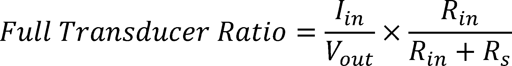
Where: Iin is the current through the current transducer, Vout is the voltage out of the transducer, Rin is the power analyzer impedance, and Rs is the current probe output impedance.
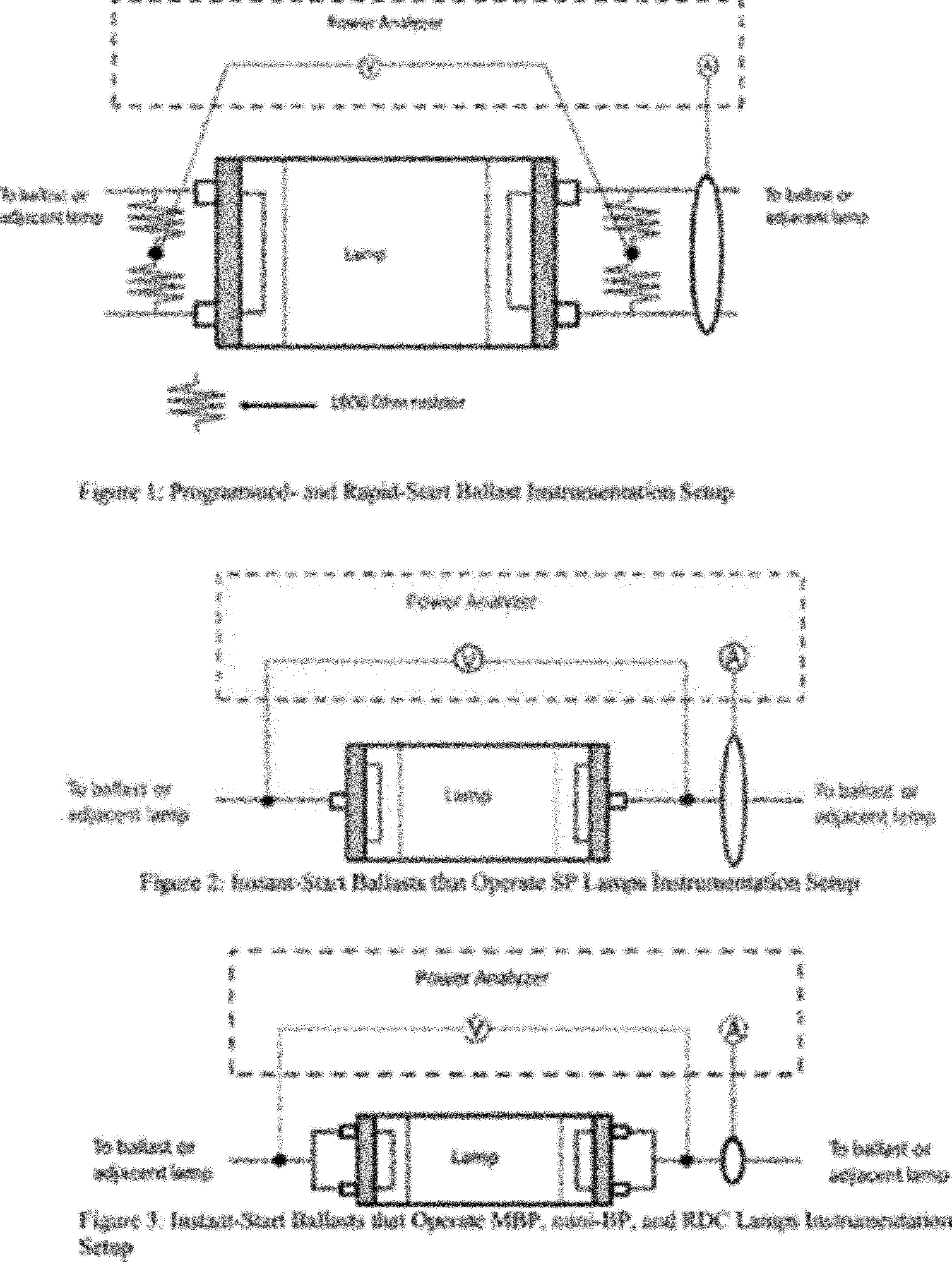
2.4. Test Conditions
2.4.1. Establish and maintain test conditions for testing fluorescent lamp ballasts in accordance with sections 3 and 4 of ANSI C82.2.
2.4.2. Room Temperature and Air Circulation. Maintain the test area at 25 ±1 °C, with minimal air movement as defined in section 4 of ANSI C78.375A.
2.4.3. Input Voltage. For any ballast designed and marketed for operation at only one input voltage, test at that specified voltage. For any ballast that is neither a residential ballast nor a sign ballast but is designed and marketed for operation at multiple voltages, test the ballast at 277 V ±0.1%. For any residential ballast or sign ballast designed and marketed for operation at multiple voltages, test the ballast at 120 V ±0.1%.
2.5. Test Method
2.5.1. Connect the ballast to the selected fluorescent lamps (as determined in section 2.3.3 of this appendix) and to measurement instrumentation as specified in the Test Setup in section 2.3 of this appendix.
2.5.2. Determine stable operating conditions according to Option 1 or Option 2.
2.5.2.1. Option 1. Operate the ballast for at least 15 minutes before determining stable operating conditions. Determine stable operating conditions by measuring lamp arc voltage, current, and power once per minute in accordance with the setup described in section 2.3 of this appendix. The system is stable once the difference between the maximum and minimum for each value of lamp arc voltage, current, and power divided by the average value of the measurements do not exceed one percent over a four minute moving window. Once stable operating conditions are reached, measure each of the parameters described in sections 2.5.3 through 2.5.9 of this appendix.
2.5.2.2 Option 2. Determine stable operating conditions for lamp arc voltage, current, and power according to steps 1 through 6 of section D.2.1 in Annex D of ANSI C82.11.
2.5.3. Lamp Arc Voltage. Measure lamp arc voltage in volts (RMS) using the setup in section 2.3.4.2.
2.5.4. Lamp Arc Current. Measure lamp arc current in amps (RMS) using the setup in section 2.3.4.3 of this appendix.
2.5.5. Lamp Arc Power. The power analyzer must calculate output power by using the measurements from sections 2.5.3 and 2.5.4 of this appendix.
2.5.6. Input Power. Measure the input power in watts to the ballast in accordance with section 7 of ANSI C82.2 (disregard references to Figure 1 and Figure 3).
2.5.7. Input Voltage. Measure the input voltage in volts (RMS) to the ballast in accordance with section 7 of ANSI C82.2 (disregard references to Figure 1 and Figure 3).
2.5.8. Input Current. Measure the input current in amps (RMS) to the ballast in accordance with section 7 of ANSI C82.2 (disregard references to Figure 1 and Figure 3).
2.5.9. Lamp Operating Frequency. Measure the frequency of the waveform delivered from the ballast to any lamp used in the test in accordance with the setup in section 2.3 of this appendix.
2.6. Calculations
2.6.1. Calculate ballast luminous efficiency (BLE) as follows (do not round values of total lamp arc power and input power prior to calculation):

Where: Total Lamp Arc Power is the sum of the lamp arc powers for all lamps operated by the ballast as measured in section 2.5.5 of this appendix, Input Power is as determined by section 2.5.6 of this appendix, and β is equal to the frequency adjustment factor in Table 1 of this appendix.
2.6.2. Calculate Power Factor (PF) as follows (do not round values of input power, input voltage, and input current prior to calculation):

Where: Input Power is measured in accordance with section 2.5.6 of this appendix, Input Voltage is measured in accordance with section 2.5.7 of this appendix, and Input Current is measured in accordance with section 2.5.8 of this appendix.
3. Standby Mode Procedure
3.1. The measurement of standby mode power is required to be performed only if a manufacturer makes any representations with respect to the standby mode power use of the fluorescent lamp ballast. When there is a conflict, the language of the test procedure in this appendix takes precedence over IEC 62301 (incorporated by reference; see § 430.3). Specifications in referenced standards that are not clearly mandatory are mandatory. Manufacturer's instructions, such as “instructions for use” referenced in IEC 62301 mean the manufacturer's instructions that come packaged with or appear on the unit, including on a label. It may include an online manual if specifically referenced (e.g., by date or version number) either on a label or in the packaged instructions. Instructions that appear on the unit take precedence over instructions available electronically, such as through the internet.
3.2. Test Setup
3.2.1. Take all measurements with instruments as specified in section 2.2 of this appendix. Fluorescent lamp ballasts that are designed and marketed for connection to control devices must be tested with all commercially available compatible control devices connected in all possible configurations. For each configuration, a separate measurement of standby power must be made in accordance with section 3.4 of this appendix.
3.2.2. Connect each ballast to the maximum number of lamp(s) as specified in section 2.3 (specifications in 2.3.3.1 are optional) of this appendix. Note: ballast operation with reference lamp(s) is not required.
3.3. Test Conditions
3.3.1. Establish and maintain test conditions in accordance with section 2.4 of this appendix.
3.4. Test Method and Measurements
3.4.1. Turn on all of the lamps at full light output.
3.4.2. Send a signal to the ballast instructing it to have zero light output using the appropriate ballast communication protocol or system for the ballast being tested.
3.4.3. Stabilize the ballast prior to measurement using one of the methods as specified in section 5 of IEC 62301.
3.4.4. Measure the standby mode energy consumption in watts using one of the methods as specified in section 5 of IEC 62301.
[85 FR 56494, Sept. 14, 2020]
Appendix R to Subpart B of Part 430 - Uniform Test Method for Measuring Average Lamp Efficacy (LE), Color Rendering Index (CRI), and Correlated Color Temperature (CCT) of Electric Lamps
1. Scope: This appendix applies to the measurement of lamp lumens, electrical characteristics, CRI, and CCT for general service fluorescent lamps, and to the measurement of lamp lumens, electrical characteristics for general service incandescent lamps and incandescent reflector lamps.
2. Definitions
2.1 To the extent that definitions in the referenced IESNA and CIE standards do not conflict with the DOE definitions, the definitions specified in section 3.0 of IES LM-9 (incorporated by reference; see § 430.3), section 3.0 of IESNA LM-20 (incorporated by reference; see § 430.3), section 3.0 and the Glossary of IES LM-45 (incorporated by reference; see § 430.3), section 2 of IESNA LM-58 (incorporated by reference; see § 430.3), and Appendix 1 of CIE 13.3 (incorporated by reference; see § 430.3) shall be included.
2.2 ANSI Standard means a standard developed by a committee accredited by the American National Standards Institute (ANSI).
2.3 CIE means the International Commission on Illumination.
2.4 CRI means Color Rendering Index as defined in § 430.2.
2.5 IESNA means the Illuminating Engineering Society of North America.
2.6 Lamp efficacy means the ratio of measured lamp lumen output in lumens to the measured lamp electrical power input in watts, rounded to the nearest tenth, in units of lumens per watt.
2.7 Lamp lumen output means the total luminous flux produced by the lamp, at the reference condition, in units of lumens.
2.8 Lamp electrical power input means the total electrical power input to the lamp, including both arc and cathode power where appropriate, at the reference condition, in units of watts.
2.9 Reference condition means the test condition specified in IES LM-9 for general service fluorescent lamps, in IESNA LM-20 for incandescent reflector lamps, and in IES LM-45 for general service incandescent lamps.
3. Test Conditions
3.1 General Service Fluorescent Lamps: For general service fluorescent lamps, the ambient conditions of the test and the electrical circuits, reference ballasts, stabilization requirements, instruments, detectors, and photometric test procedure and test report shall be as described in the relevant sections of IES LM-9 (incorporated by reference; see § 430.3).
3.2 General Service Incandescent Lamps: For general service incandescent lamps, the selection and seasoning (initial burn-in) of the test lamps, the equipment and instrumentation, and the test conditions shall be as described in IES LM-45 (incorporated by reference; see § 430.3).
3.3 Incandescent Reflector Lamps: For incandescent reflector lamps, the selection and seasoning (initial burn-in) of the test lamps, the equipment and instrumentation, and the test conditions shall conform to sections 4.2 and 5.0 of IESNA LM-20 (incorporated by reference; see § 430.3).
4. Test Methods and Measurements
All lumen measurements made with instruments calibrated to the devalued NIST lumen after January 1, 1996, shall be multiplied by 1.011.
4.1 General Service Fluorescent Lamps
4.1.1 The measurement procedure shall be as described in IES LM-9 (incorporated by reference; see § 430.3), except that lamps shall be operated at the appropriate voltage and current conditions as described in ANSI C78.375 (incorporated by reference; see § 430.3) and in ANSI C78.81 (incorporated by reference; see § 430.3) or ANSI C78.901 (incorporated by reference; see § 430.3), and lamps shall be operated using the appropriate reference ballast at input voltage specified by the reference circuit as described in ANSI C82.3 (incorporated by reference; see § 430.3). If, for a lamp, both low-frequency and high-frequency reference ballast settings are included in ANSI C78.81 or ANSI C78.901, the lamp shall be operated using the low-frequency reference ballast.
4.1.2 For lamps not listed in ANSI C78.81 (incorporated by reference; see § 430.3) nor in ANSI C78.901 (incorporated by reference; see § 430.3), the lamp shall be operated using the following reference ballast settings:
4.1.2.1 4-Foot medium bi-pin lamps shall be operated using the following reference ballast settings: T10 or T12 lamps are to use 236 volts, 0.43 amps, and 439 ohms; T8 lamps are to use 300 volts, 0.265 amps, and 910 ohms.
4.1.2.2 2-Foot U-shaped lamps shall be operated using the following reference ballast settings: T12 lamps are to use 236 volts, 0.430 amps, and 439 ohms; T8 lamps are to use 300 volts, 0.265 amps, and 910 ohms.
4.1.2.3 8-foot slimline lamps shall be operated using the following reference ballast settings:
(a) T12 lamps: 625 volts, 0.425 amps, and 1280 ohms.
(b) T8 lamps: 625 volts, 0.260 amps, and 1960 ohms.
4.1.2.4 8-foot high output lamps shall be operated using the following reference ballast settings:
(a) T12 lamps: 400 volts, 0.800 amps, and 415 ohms.
(b) T8 lamps: 450 volts, 0.395 amps, and 595 ohms.
4.1.2.5 4-foot miniature bipin standard output or high output lamps shall be operated using the following reference ballast settings:
(a) Standard Output: 329 volts, 0.170 amps, and 950 ohms.
(b) High Output: 235 volts, 0.460 amps, and 255 ohms.
4.1.3 Lamp lumen output (lumens) and lamp electrical power input (watts), at the reference condition, shall be measured and recorded. Lamp efficacy shall be determined by computing the ratio of the measured lamp lumen output and lamp electrical power input at equilibrium for the reference condition.
4.2 General Service Incandescent Lamps
4.2.1 The measurement procedure shall be as described in IES LM-45 (incorporated by reference; see § 430.3). Lamps shall be operated at the rated voltage as defined in § 430.2.
4.2.2 The test procedure shall conform to sections 6 and 7 of IES LM-45, and the lumen output of the lamp shall be determined in accordance with section 7 of IES LM-45. Lamp electrical power input in watts shall be measured and recorded. Lamp efficacy shall be determined by computing the ratio of the measured lamp lumen output and lamp electrical power input at equilibrium for the reference condition. The test report shall conform to section 8 of IES LM-45.
4.2.3 The measurement procedure for testing the lifetime of general service incandescent lamps shall be as described in IESNA LM-49 (incorporated by reference; see § 430.3). The lifetime measurement shall be taken by measuring the operating time of a lamp, expressed in hours, not including any off time. The percentage of the sample size that meets the minimum rated lifetime shall be recorded. The lamp shall be deemed to meet minimum rated lifetime standards if greater than 50 percent of the sample size specified in § 429.27 meets the minimum rated lifetime.
4.2.3.1 Accelerated lifetime testing is not allowed. The second paragraph of section 6.1 of IESNA LM-49 is to be disregarded.
4.3 Incandescent Reflector Lamps
4.3.1 The measurement procedure shall be as described in IESNA LM-20 (see 10 CFR 430.22). Lamps shall be operated at the rated voltage as defined in § 430.2.
4.3.2. Lamp lumen output shall be determined as total forward lumens, and may be measured in an integrating sphere at the reference condition in accordance with § 7.2 of IESNA LM-20 (incorporated by reference; see § 430.3) or from an average intensity distribution curve measured at the reference condition specified in § 6.0 of IESNA LM-20. Lamp electrical power input in watts shall be measured and recorded.
4.3.3 Lamp efficacy shall be determined by computing the ratio of the measured lamp lumen output and lamp electrical power input at equilibrium for the reference condition. The test report shall conform to section 10.0 of IES LM-20 (incorporated by reference; see § 430.3).
4.4 Determination of Color Rendering Index and Correlated Color Temperature
4.4.1 The CRI shall be determined in accordance with the method specified in CIE 13.3 (incorporated by reference; see § 430.3) for general service fluorescent lamps. The CCT shall be determined in accordance with the method specified in IES LM-9 (incorporated by reference; see § 430.3) and rounded to the nearest 10 kelvin for general service fluorescent lamps. The CCT shall be determined in accordance with the CIE 15 (incorporated by reference; see § 430.3) for incandescent lamps. The required spectroradiometric measurement and characterization shall be conducted in accordance with the methods set forth in IESNA LM-58 (incorporated by reference; see § 430.3).
4.4.2 The test report shall include a description of the test conditions, equipment, measured lamps, spectroradiometric measurement results, and CRI and CCT determinations.
[62 FR 29240, May 29, 1997, as amended at 74 FR 34177, July 14, 2009; 77 FR 4217, Jan. 27, 2012]
Appendix S to Subpart B of Part 430—Uniform Test Method for Measuring the Water Consumption of Faucets and Showerheads
After April 21, 2014, any representations made with respect to the water consumption of showerheads or faucets must be made in accordance with the results of testing pursuant to this appendix.
Manufacturers conducting tests of showerheads or faucets November 22, 2013 and prior to April 21, 2014, must conduct such test in accordance with either this appendix or appendix S as it appeared at 10 CFR part 430, subpart B, appendix S, in the 10 CFR parts 200 to 499 edition revised as of January 1, 2013. Any representations made with respect to the water consumption of such showerheads or faucets must be in accordance with whichever version is selected. Given that after April 21, 2014 representations with respect to the water consumption of showerheads and faucets must be made in accordance with tests conducted pursuant to this appendix, manufacturers may wish to begin using this test procedure as soon as possible.
1. Scope: This appendix covers the test requirements used to measure the hydraulic performance of faucets and showerheads.
2. Flow Capacity Requirements
a. Faucets—The test procedures to measure the water flow rate for faucets, expressed in gallons per minute (gpm) and liters per minute (L/min), or gallons per cycle (gal/cycle) and liters per cycle (L/cycle), shall be conducted in accordance with the test requirements specified in section 5.4, Flow Rate, of ASME A112.18.1-2012 (incorporated by reference, see § 430.3). Measurements shall be recorded at the resolution of the test instrumentation. Calculations shall be rounded off to the same number of significant digits as the previous step. The final water consumption value shall be rounded to one decimal place for non-metered faucets, or two decimal places for metered faucets.
b. Showerheads—The test procedures to measure the water flow rate for showerheads, expressed in gallons per minute (gpm) and liters per minute (L/min), shall be conducted in accordance with the test requirements specified in section 5.4, Flow Rate, of the ASME A112.18.1-2012 (incorporated by reference, see § 430.3). Measurements shall be recorded at the resolution of the test instrumentation. Calculations shall be rounded off to the same number of significant digits as the previous step. The final water consumption value shall be rounded to one decimal place. If the time/volume method of section 5.4.2.2(d) is used, the container must be positioned as to collect all water flowing from the showerhead, including any leakage from the ball joint.
[63 FR 13316, Mar. 18, 1998, as amended at 78 FR 62986, Oct. 23, 2013]
Appendix T to Subpart B of Part 430 - Uniform Test Method for Measuring the Water Consumption of Water Closets and Urinals
After April 21, 2014, any representations made with respect to the water consumption of water closets or urinals must be made in accordance with the results of testing pursuant to this appendix.
Manufacturers conducting tests of water closets or urinals after November 22, 2013 and prior to April 21, 2014, must conduct such test in accordance with either this appendix or appendix T as it appeared at 10 CFR part 430, subpart B, appendix S, in the 10 CFR parts 200 to 499 edition revised as of January 1, 2013. Any representations made with respect to the water consumption of such water closets or urinals must be in accordance with whichever version is selected. Given that after April 21, 2014 representations with respect to the water consumption of water closets and urinals must be made in accordance with tests conducted pursuant to this appendix, manufacturers may wish to begin using this test procedure as soon as possible.
1. Scope: This appendix covers the test requirements used to measure the hydraulic performances of water closets and urinals.
2. Test Apparatus and General Instructions
a. The test apparatus and instructions for testing water closets shall conform to the requirements specified in section 7.1, General, subsections 7.1.1, 7.1.2, 7.1.3, 7.1.4, and 7.1.5 of ASME A112.19.2-2008 (incorporated by reference, see § 430.3). The flushometer valve used in the water consumption test shall represent the maximum design flush volume of the water closet. Measurements shall be recorded at the resolution of the test instrumentation. Calculations of water consumption for each tested unit shall be rounded off to the same number of significant digits as the previous step.
b. The test apparatus and instructions for testing urinals shall conform to the requirements specified in section 8.2, Test Apparatus and General Instructions, subsections 8.2.1, 8.2.2, and 8.2.3 of ASME A112.19.2-2008 (incorporated by reference, see § 430.3). The flushometer valve used in the water consumption test shall represent the maximum design flush volume of the urinal. Measurements shall be recorded at the resolution of the test instrumentation. Calculations of water consumption for each tested unit shall be rounded off to the same number of significant digits as the previous step.
3. Test Measurement
a. Water closets:
(i) The measurement of the water flush volume for water closets, expressed in gallons per flush (gpf) and liters per flush (Lpf), shall be conducted in accordance with the test requirements specified in section 7.4, Water Consumption Test, of ASME A112.19.2-2008 (incorporated by reference, see § 430.3). For dual-flush water closets, the measurement of the water flush volume shall be conducted separately for the full-flush and reduced-flush modes and in accordance with the test requirements specified section 7.4, Water Consumption Test, of ASME A112.19.2-2008.
(ii) Static pressure requirements: The water consumption tests of siphonic and blowout water closets shall be conducted at two static pressures. For flushometer valve water closets with a siphonic bowl, the test pressures shall be 80 psi and 35 psi. For flushometer valve water closets with a blowout bowl, the test pressures shall be 80 psi and 45 psi. The test shall be run three times at each pressure as specified in section 7.4.3 “Procedure,” of ASME A112.19.2-2008 (incorporated by reference, see § 430.3). The final measured flush volume for each tested unit shall be the average of the total flush volumes recorded at each test pressure as specified in section 7.4.5 “Performance,” of ASME A112.19.2-2008.
(iii) Flush volume and tank trim component adjustments: For gravity flush tank water closets, trim components that can be adjusted to cause an increase in flush volume, including (but not limited to) the flapper valve, fill valve, and tank water level, shall be set in accordance with the printed installation instructions supplied by the manufacturer. If the installation instructions for the model to be tested do not specify trim setting adjustments, these trim components shall be adjusted to the maximum water use setting so that the maximum flush volume is produced without causing the water closet to malfunction or leak. The water level in the tank shall be set to the maximum water line designated in the printed installation instructions supplied by the manufacturer or the designated water line on the tank itself, whichever is higher. If the printed installation instructions or the water closet tank do not indicate a water level, the water level shall be adjusted to 1±0.1 inches below the top of the overflow tube or 1±0.1 inches below the top rim of the water-containing vessel (for gravity flush tank water closets that do not contain an overflow tube) for each designated pressure specified in Table 5 of ASME A112.19.2-2008 (incorporated by reference, see § 430.3).
b. Urinals - The measurement of water flush volume for urinals, expressed in gallons per flush (gpf) and liters per flush (Lpf), shall be conducted in accordance with the test requirements specified in section 8.6, Water Consumption Test, of ASME A112.19.2-2008 (incorporated by reference, see § 430.3). The final measured flush volume for each tested unit shall be the average of the total flush volumes recorded at each test pressure as specified in section 8.6.4 “Performance,” of ASME A112.19.2-2008.
[63 FR 13317, Mar. 18, 1998, as amended at 78 FR 62987, Oct. 23, 2013]
Appendix U to Subpart B of Part 430 - Uniform Test Method for Measuring the Energy Consumption of Ceiling Fans
Prior to January 23, 2017, manufacturers must make any representations with respect to the energy use or efficiency of ceiling fans as specified in Section 2 of this appendix (other than hugger ceiling fans, multi-mount ceiling fans in the hugger configuration, and large-diameter ceiling fans) in accordance with the results of testing pursuant either to this appendix, or to the applicable test requirements set forth in 10 CFR parts 429 and 430, as they appeared in the 10 CFR parts 200 to 499 edition revised as of January 1, 2016. On or after January 23, 2017, manufacturers of ceiling fans, as specified in Section 2 of this appendix, must make any representations with respect to energy use or efficiency in accordance with the results of testing pursuant to this appendix.
1. Definitions:
1.1. 40% speed means the ceiling fan speed at which the blade RPM are measured to be 40% of the blade RPM measured at high speed.
1.2. Airflow means the rate of air movement at a specific fan-speed setting expressed in cubic feet per minute (CFM).
1.3. Belt-driven ceiling fan means a ceiling fan with a series of one or more fan heads, each driven by a belt connected to one or more motors that are located outside of the fan head.
1.4. Blade span means the diameter of the largest circle swept by any part of the fan blade assembly, including any blade attachments.
1.5. Ceiling fan efficiency means the ratio of the total airflow to the total power consumption, in units of cubic feet per minute per watt (CFM/W).
1.6. Centrifugal ceiling fan means a ceiling fan for which the primary airflow direction is in the same plane as the rotation of the fan blades.
1.7. High speed means the highest available ceiling fan speed, i.e., the fan speed corresponding to the maximum blade revolutions per minute (RPM).
1.8. High-speed small-diameter ceiling fan means a small-diameter ceiling fan that is not a very-small-diameter ceiling fan, highly-decorative ceiling fan or belt-driven ceiling fan and that has a blade thickness of less than 3.2 mm at the edge or a maximum tip speed greater than the applicable limit specified in the table in this definition.
High-Speed Small-Diameter Ceiling Fan Blade and Tip Speed Criteria
| Airflow direction | Thickness (t) of edges of blades | Tip speed threshold | ||
|---|---|---|---|---|
| Mm | inch | m/s | feet per minute | |
| Downward-only | 4.8 > t ≥ 3.2 | 3/16 > t ≥ 1/8 | 16.3 | 3,200 |
| Downward-only | t ≥ 4.8 | t ≥ 3/16 | 20.3 | 4,000 |
| Reversible | 4.8 > t ≥ 3.2 | 3/16 > t ≥ 1/8 | 12.2 | 2,400 |
| Reversible | t ≥ 4.8 | t ≥ 3/16 | 16.3 | 3,200 |
1.9. Highly-decorative ceiling fan means a ceiling with a maximum rotational speed of 90 RPM and less than 1,840 CFM airflow at high speed, as determined by sections 3 and 4 of this appendix.
1.10. Hugger ceiling fan means a low-speed small-diameter ceiling fan that is not a very-small-diameter ceiling fan, highly-decorative ceiling fan or belt-driven ceiling fan; for which the lowest point on the fan blades is less than or equal to 10 inches from the ceiling.
1.11. Large-diameter ceiling fan means a ceiling fan that is greater than seven feet in diameter.
1.12. Low speed means the lowest available ceiling fan speed, i.e., the fan speed corresponding to the minimum, non-zero, blade RPM.
1.13. Low-speed small-diameter ceiling fan means a small-diameter ceiling fan that has a blade thickness greater than or equal to 3.2 mm at the edge and a maximum tip speed less than or equal to the applicable limit specified in the table in this definition.
Low-Speed Small-Diameter Ceiling Fan Blade and Tip Speed Criteria
| Airflow direction | Thickness (t) of edges of blades | Tip speed threshold | ||
|---|---|---|---|---|
| Mm | inch | m/s | feet per minute | |
| Reversible | 4.8 > t ≥ 3.2 | 3/16 > t ≥ 1/8 | 12.2 | 2,400 |
| Reversible | t ≥ 4.8 | t ≥ 3/16 | 16.3 | 3,200 |
1.14. Multi-head ceiling fan means a ceiling fan with more than one fan head, i.e., more than one set of rotating fan blades.
1.15. Multi-mount ceiling fan means a low-speed small-diameter ceiling fan that can be mounted in the configurations associated with both the standard and hugger ceiling fans.
1.16. Oscillating ceiling fan means a ceiling fan containing one or more fan heads for which the axis of rotation of the fan blades cannot remain in a fixed position relative to the ceiling. Such fans have no inherent means by which to disable the oscillating function separate from the fan blade rotation.
1.17. Small-diameter ceiling fan means a ceiling fan that is less than or equal to seven feet in diameter.
1.18. Standard ceiling fan means a low-speed small-diameter ceiling fan that is not a very-small-diameter ceiling fan, highly-decorative ceiling fan or belt-driven ceiling fan; for which the lowest point on fan blades is greater than 10 inches from the ceiling.
1.19. Total airflow means the sum of the product of airflow and hours of operation at all tested speeds. For multi-head fans, this includes the airflow from all fan heads.
1.20. Very-small-diameter ceiling fan means a small-diameter ceiling fan that is not a highly-decorative ceiling fan or belt-driven ceiling fan; and has one or more fan heads, each of which has a blade span of 18 inches or less.
2. Scope:
The provisions in this appendix apply to ceiling fans except:
(1) Ceiling fans where the plane of rotation of a ceiling fan's blades is not less than or equal to 45 degrees from horizontal, or cannot be adjusted based on the manufacturer's specifications to be less than or equal to 45 degrees from horizontal;
(2) Centrifugal ceiling fans;
(3) Belt-driven ceiling fans; and
(4) Oscillating ceiling fans.
3. General Instructions, Test Apparatus, and Test Measurement:
The test apparatus and test measurement used to determine energy performance depend on the ceiling fan's blade span. For each tested ceiling fan, measure the lateral distance from the center of the axis of rotation of the fan blades to the furthest fan blade edge from the center of the axis of rotation, and multiply this distance by two. The blade span for a basic model of ceiling fan is then calculated as the arithmetic mean of this distance across each ceiling fan in the sample, rounded to the nearest inch.
3.1. General instructions.
3.1.1. Record measurements at the resolution of the test instrumentation. Round off calculations to the number of significant digits present at the resolution of the test instrumentation, except for blade span, which is rounded to the nearest inch. Round the final ceiling fan efficiency value to the nearest whole number as follows:
3.1.1.1. A fractional number at or above the midpoint between the two consecutive whole numbers shall be rounded up to the higher of the two whole numbers; or
3.1.1.2. A fractional number below the midpoint between the two consecutive whole numbers shall be rounded down to the lower of the two whole numbers.
3.1.2. For multi-head ceiling fans, the effective blade span is the blade span (as specified in section 3) of an individual fan head, if all fan heads are the same size. If the fan heads are of varying sizes, the effective blade span is the blade span (as specified in section 3) of the largest fan head.
3.2. Test apparatus for low-speed small-diameter and high-speed small-diameter ceiling fans: All instruments are to have accuracies within ±1% of reading, except for the air velocity sensors, which must have accuracies within ±5% of reading or 2 feet per minute (fpm), whichever is greater. Equipment is to be calibrated at least once a year to compensate for variation over time.
3.2.1. Air Delivery Room Requirements
(1) The air delivery room dimensions are to be 20 ± 0.75 feet x 20 ± 0.75 feet with an 11 ± 0.75 foot-high ceiling. The control room shall be constructed external to the air delivery room.
(2) The ceiling shall be constructed of sheet rock or stainless plate. The walls must be of adequate thickness to maintain the specified temperature and humidity during the test. The paint used on the walls, as well as the paint used on the ceiling material, must be of a type that minimizes absorption of humidity and that keeps the temperature of the room constant during the test (e.g., oil-based paint).
(3) The room must not have any ventilation other than an air conditioning and return system used to control the temperature and humidity of the room. The construction of the room must ensure consistent air circulation patterns within the room. Vents must have electronically-operated damper doors controllable from a switch outside of the testing room.
3.2.2. Equipment Set-Up
(1) Make sure the transformer power is off. Hang the ceiling fan to be tested directly from the ceiling, according to the manufacturer's installation instructions. Hang all non-multi-mount ceiling fans in the fan configuration that minimizes the distance between the ceiling and the lowest point of the fan blades. Hang and test multi-mount fans in two configurations: The configuration associated with the definitions of a standard fan that minimizes the distance between the ceiling and the lowest point of the fan blades and the configuration associated with the definition of a hugger fan that minimizes the distance between the ceiling and the lowest point of the fan blades.
(2) Connect wires as directed by manufacturer's wiring instructions. Note: Assemble fan prior to the test; lab personnel must follow the instructions provided with the fan by the fan manufacturer. Balance the fan blade assembly in accordance with the manufacturer's instructions to avoid excessive vibration of the motor assembly (at any speed) during operation.
(3) With the ceiling fan installed, adjust the height of the air velocity sensors to ensure the vertical distance between the lowest point on the ceiling fan blades and the air velocity sensors is 43 inches.
(4) Either a rotating sensor arm or four fixed sensor arms can be used to take airflow measurements along four axes, labeled A-D. Axes A, B, C, and D are at 0, 90, 180, and 270 degree positions. Axes A-D must be perpendicular to the four walls of the room. See Figure 1 of this appendix.

(5) Minimize the amount of exposed wiring. Store all sensor lead wires under the floor, if possible.
(6) Place the sensors at intervals of 4 ± 0.0625 inches along a sensor arm, starting with the first sensor at the point where the four axes intersect. Do not touch the actual sensor prior to testing. Use enough sensors to record air delivery within a circle 8 inches larger in diameter than the blade span of the ceiling fan being tested. The experimental set-up is shown in Figure 2 of this appendix.

(7) Table 1 of this appendix shows the appropriate number of sensors needed per each of four axes (including the first sensor at the intersection of the axes) for common fan sizes.
Table 1 to Appendix U to Subpart B of Part 430: Sensor Selection Requirements
| Fan blade
span * (inches) |
Number
of sensors |
|---|---|
| 36 | 6 |
| 42 | 7 |
| 44 | 7 |
| 48 | 7 |
| 52 | 8 |
| 54 | 8 |
| 56 | 8 |
| 60 | 9 |
| 72 | 10 |
| 84 | 12 |
(8) Install an RPM (revolutions per minute) meter, or tachometer, to measure RPM of the ceiling fan blades.
(9) Use an RMS sensor capable of measuring power with an accuracy of ±1% to measure ceiling fan power consumption. If the ceiling fan operates on multi-phase power input, measure the active (real) power in all phases simultaneously. Measure test voltage within 6” of the connection supplied with the ceiling fan.
(10) Complete any conditioning instructions provided in the ceiling fan's instruction or installation manual must be completed prior to conducting testing.
3.2.3. Multi-Head Ceiling Fan Test Set-Up
Hang a multi-headed ceiling fan from the ceiling such that one of the ceiling fan heads is centered directly over sensor 1 (i.e., at the intersection of axes A, B, C, and D). The distance between the lowest point any of the fan blades of the centered fan head can reach and the air velocity sensors is to be such that it is the same as for all other small-diameter ceiling fans (see Figure 2 of this appendix). If the multi-head ceiling fan has an oscillating function (i.e., the fan heads change their axis of rotation relative to the ceiling) that can be switched off, switch it off prior to taking airflow measurements. If any multi-head fan does not come with the blades preinstalled, install fan blades only on the fan head that will be directly centered over the intersection of the sensor axes. (Even if the fan heads in a multi-head ceiling fan would typically oscillate when the blades are installed on all fan heads, the ceiling fan is subject to this test procedure if the centered fan head does not oscillate when it is the only fan head with the blades installed.) If the fan blades are preinstalled on all fan heads, measure airflow in accordance with section 3.3 except only turn on the centered fan head. Measure the power consumption measurements are to be made separately, with the fan blades installed on all fan heads and with any oscillating function, if present, switched on.
3.2.4. Test Set-Up for Ceiling Fans with Airflow Not Directly Downward
For ceiling fans where the airflow is not directly downward, adjust the ceiling fan head such that the airflow is as vertical as possible prior to testing. For ceiling fans where a fully vertical orientation of airflow cannot be achieved, orient the ceiling fan (or fan head, if the ceiling fan is a multi-head fan) such that any remaining tilt is aligned along one of the four sensor axes. Instead of measuring the air velocity for only those sensors directly beneath the ceiling fan, the air velocity is to be measured at all sensors along that axis, as well as the axis oriented 180 degrees with respect to that axis. For example, if the tilt is oriented along axis A, air velocity measurements are to be taken for all sensors along the A-C axis. No measurements would need to be taken along the B-D axis in this case. All other aspects of test set-up remain unchanged from sections 3 through 3.2.2.
3.3. Active mode test measurement for low-speed small-diameter and high-speed small-diameter ceiling fans.
3.3.1. Test conditions to be followed when testing:
(1) Maintain the room temperature at 70 degrees ± 5 degrees Fahrenheit and the room humidity at 50% ± 5% relative humidity during the entire test process.
(2) If present, the ceiling fan light fixture is to be installed but turned off during testing.
(3) If present, any heater is to be installed but turned off during testing.
(4) If present, turn off any oscillating function causing the axis of rotation of the fan head(s) to change relative to the ceiling during operation prior to taking airflow measurements. Turn on any oscillating function prior to taking power measurements.
(5) The supply voltage shall be:
(i) 120 V if the ceiling fan's minimum rated voltage is 120 V or the lowest rated voltage range contains 120 V,
(ii) 240 V if the ceiling fan's minimum rated voltage is 240 V or the lowest rated voltage range contains 240 V, or
(iii) The ceiling fan's minimum rated voltage (if a voltage range is not given) or the mean of the lowest rated voltage range, in all other cases. The test voltage shall not vary by more than ±1% during the tests.
(6) Test ceiling fans rated for operation with only a single- or multi-phase power supply with single- or multi-phase electricity, respectively. Measure active (real) power in all phases continuously when testing. Test ceiling fans capable of operating with single- and multi-phase electricity with single-phase electricity. DOE will allow manufacturers of ceiling fans capable of operating with single- and multi-phase electricity to test such fans with multi-phase power and make representations of efficiency associated with both single and multi-phase electricity if a manufacturer desires to do so, but the test results in the multi-phase configuration will not be valid to assess compliance with any amended energy conservation standard.
(7) Conduct the test with the fan connected to a supply circuit at the rated frequency.
(8) Measure power input at a point that includes all power-consuming components of the ceiling fan (but without any attached light kit or heater energized).
3.3.2. Airflow and Power Consumption Testing Procedure:
Measure the airflow (CFM) and power consumption (W) for HSSD ceiling fans until stable measurements are achieved, measuring at high speed only. Measure the airflow and power consumption for LSSD ceiling fans until stable measurements are achieved, measuring first at low speed and then at high speed. Airflow and power consumption measurements are considered stable if:
(1) The average air velocity for all axes for each sensor varies by less than 5% compared to the average air velocity measured for that same sensor in a successive set of air velocity measurements, and
(2) Average power consumption varies by less than 1% in a successive set of power consumption measurements. These stability criteria are applied differently to ceiling fans with airflow not directly downward. See section 4.1.2 of this appendix.
Step 1: Set the first sensor arm (if using four fixed arms) or single sensor arm (if using a single rotating arm) to the 0 degree Position (Axis A). If necessary, use a marking as reference. If using a single rotating arm, adjust the sensor arm alignment until it is at the 0 degree position by remotely controlling the antenna rotator.
Step 2: Set software up to read and record air velocity, expressed in feet per minute (FPM) in 1 second intervals. (Temperature does not need to be recorded in 1 second intervals.) Record current barometric pressure.
Step 3: Allow test fan to run 15 minutes at rated voltage and at high speed if the ceiling fan is an HSSD ceiling fan. If the ceiling fan is an LSSD ceiling fan, allow the test fan to run 15 minutes at the rated voltage and at low speed. Turn off all forced-air environmental conditioning equipment entering the chamber (e.g., air conditioning), close all doors and vents, and wait an additional 3 minutes prior to starting test session.
Step 4: Begin recording readings. Take 100 airflow velocity readings (100 seconds run-time) and save these data. If using a rotating sensor arm, this is axis A. For all fans except multi-head fans and fans capable of oscillating, measure power during the interval that air velocity measurements are taken. Record the average value of the power measurement in watts (W).
Step 5: Similarly, take 100 air velocity readings (100 seconds run-time) for Axes B, C, and D; save these data as well. Measure power as described in Step 4. If using four fixed sensor arms, take the readings for all sensor arms simultaneously.
Step 6: Repeat Steps 4 and 5 until stable measurements are achieved.
Step 7: Repeat steps 1 through 6 above on high fan speed for LSSD ceiling fans. Note: Ensure that temperature and humidity readings are maintained within the required tolerances for the duration of the test (all tested speeds). Forced-air environmental conditioning equipment may be used and doors and vents may be opened between test sessions to maintain environmental conditions.
Step 8: If testing a multi-mount ceiling fan, repeat steps 1 through 7 with the ceiling fan in the ceiling fan configuration (associated with either hugger or standard ceiling fans) not already tested.
If a multi-head ceiling fan includes more than one category of ceiling fan head, then test at least one of each unique category. A fan head with different construction that could affect air movement or power consumption, such as housing, blade pitch, or motor, would constitute a different category of fan head.
Step 9: For multi-head ceiling fans, measure active (real) power consumption in all phases simultaneously at each speed continuously for 100 seconds with all fan heads turned on, and record the average value at each speed in watts (W).
For ceiling fans with an oscillating function, measure active (real) power consumption in all phases simultaneously at each speed continuously for 100 seconds with the oscillating function turned on. Record the average value of the power measurement in watts (W).
For both multi-head ceiling fans and fans with an oscillating function, repeat power consumption measurement until stable power measurements are achieved.
3.4. Test apparatus for large-diameter ceiling fans:
The test apparatus and instructions for testing large-diameter ceiling fans must conform to the requirements specified in sections 3 through 7 of AMCA 230-15 (incorporated by reference, see § 430.3), with the following modifications:
3.4.1. The test procedure is applicable to large-diameter ceiling fans up to 24 feet in diameter.
3.4.2. A “ceiling fan” is defined as in 10 CFR 430.2.
3.4.3. The supply voltage shall be (1) 120 V if the ceiling fan's minimum rated voltage is 120 V or the lowest rated voltage range contains 120 V, (2) 240 V if the ceiling fan's minimum rated voltage is 240 V or the lowest rated voltage range contains 240 V, or (3) the ceiling fan's minimum rated voltage (if a voltage range is not given) or the mean of the lowest rated voltage range, in all other cases.
3.4.4. Test ceiling fans rated for operation with only a single- or multi-phase power supply with single- or multi-phase electricity, respectively. Test ceiling fans capable of operating with single- and multi-phase electricity with multi-phase electricity. DOE will allow manufacturers of ceiling fans capable of operating with single- and multi-phase electricity to test such fans with single-phase power and make representations of efficiency associated with both single and multi-phase electricity if a manufacturer desires to do so, but the test results in the single-phase configuration will not be valid to assess compliance with any amended energy conservation standard.
3.5 Active mode test measurement for large-diameter ceiling fans:
(1) Test large-diameter ceiling fans in accordance with ANSI/AMCA Standard 208-18 in all phases simultaneously at:
(a) High speed, and
(b) 40 percent speed or the nearest speed that is not less than 40 percent speed.
(2) When testing at 40 percent speed for large-diameter ceiling fans that can operate over an infinite number of speeds (e.g., ceiling fans with VFDs), ensure the average measured RPM is within the greater of 1% of the average RPM at high speed or 1 RPM. For example, if the average measured RPM at high speed is 50 RPM, for testing at 40% speed, the average measured RPM should be between 19 RPM and 21 RPM. If the average measured RPM falls outside of this tolerance, adjust the ceiling fan speed and repeat the test. Calculate the airflow and measure the active (real) power consumption in all phases simultaneously in accordance with the test requirements specified in sections 8 and 9, AMCA 230-15 (incorporated by reference, see § 430.3), with the following modifications:
3.5.1. Measure active (real) power consumption in all phases simultaneously at a point that includes all power-consuming components of the ceiling fan (but without any attached light kit or heater energized).
3.5.2. Measure active (real) power consumption in all phases simultaneously continuously at the rated voltage that represents normal operation over the time period for which the load differential test is conducted.
3.6. Test measurement for standby power consumption.
(1) Measure standby power consumption if the ceiling fan offers one or more of the following user-oriented or protective functions:
☐ ☐o The ability to facilitate the activation or deactivation of other functions (including active mode) by remote switch (including remote control), internal sensor, or timer.
☐ Continuous functions, including information or status displays (including clocks), or sensor-based functions.
(2) Measure standby power consumption after completion of active mode testing and after the active mode functionality has been switched off (i.e., the rotation of the ceiling fan blades is no longer energized). The ceiling fan must remain connected to the main power supply and be in the same configuration as in active mode (i.e., any ceiling fan light fixture should still be attached). Measure standby power consumption according to sections 4 and 5.3.1 through 5.3.2 of IEC 62301-U (incorporated by reference, see § 430.3) with the following modifications:
3.6.1. Allow 3 minutes between switching off active mode functionality and beginning the standby power test. (No additional time before measurement is required.)
3.6.2. Simultaneously in all phases, measure active (real) power consumption continuously for 100 seconds, and record the average value of the standby power measurement in watts (W).
3.6.3. Determine power consumption according to section 5.3.2 of IEC 62301-U, or by using the following average reading method. Note that a shorter measurement period may be possible using the sample method in section 5.3.2 of IEC 62301-U.
(1) Connect the product to the power supply and power measuring instrument.
(2) Select the mode to be measured (which may require a sequence of operations and could require waiting for the product to automatically enter the desired mode) and then monitor the power.
(3) Calculate the average power using either the average power method or the accumulated energy method. For the average power method, where the power measuring instrument can record true average power over an operator selected period, the average power is taken directly from the power measuring instrument. For the accumulated energy method, determine the average power by dividing the measured energy by the time for the monitoring period. Use units of watt-hours and hours for both methods to determine average power in watts.
4. Calculation of Ceiling Fan Efficiency From the Test Results for LSSD and HSSD ceiling fans:
(1) The efficacy of a ceiling fan is the ceiling fan efficiency (as defined in section 1 of this appendix). Calculate two ceiling fan efficiencies for multi-mount ceiling fans: One efficiency corresponds to the ceiling fan mounted in the configuration associated with the definition of a hugger ceiling fan, and the other efficiency corresponds to the ceiling fan mounted in the configuration associated with the definition of a standard ceiling fan.
(2) Calculate fan efficiency using the average of both sets of airflow and power measurements from the successive sets of measurements that meet the stability criteria.
(3) To calculate the measured airflow for HSSD and LSSD ceiling fans, multiply the average air velocity measurement at each sensor from section 3.3 of this appendix (for high speed for HSSD ceiling fans, and for high and low speeds for LSSD ceiling fans) with the sensor's effective area (explained below), and then sum the products to obtain the overall measured airflow at the tested speed. Using the airflow and the power consumption measurements from sections 3.3 and 3.5 of this appendix calculate the efficiency for any ceiling fan as follows:

Where:
CFMi = airflow at speed i,
OHi = operating hours at speed i,
Wi = power consumption at speed i,
OHSb = operating hours in standby mode, and
WSb = power consumption in standby mode.
(4) Table 3 of this appendix specifies the daily hours of operation to be used in calculating ceiling fan efficiency:
Table 3 to Appendix U to Subpart B of Part 430: Daily Operating Hours for Calculating Ceiling Fan Efficiency
| No standby | With
standby |
|
|---|---|---|
| Daily Operating Hours for LSSD Ceiling Fans | ||
| High Speed | 3.4 | 3.4 |
| Low Speed | 3.0 | 3.0 |
| Standby Mode | 0.0 | 17.6 |
| Off Mode | 17.6 | 0.0 |
| Daily Operating Hours for HSSD Ceiling Fans | ||
| High Speed | 12.0 | 12.0 |
| Standby Mode | 0.0 | 12.0 |
| Off Mode | 12.0 | 0.0 |
(5) Calculate the effective area corresponding to each sensor used in the test method for small-diameter ceiling fans with the following equations:
(6) For sensor 1, the sensor located directly underneath the center of the ceiling fan, the effective width of the circle is 2 inches, and the effective area is:

(7) For the sensors between sensor 1 and the last sensor used in the measurement, the effective area has a width of 4 inches. If a sensor is a distance d, in inches, from sensor 1, then the effective area is:

(8) For the last sensor, the width of the effective area depends on the horizontal displacement between the last sensor and the point on the ceiling fan blades furthest radially from the center of the fan. The total area included in an airflow calculation is the area of a circle 8 inches larger in diameter than the ceiling fan blade span (as specified in section 3 of this appendix).
(9) Therefore, for example, for a 42-inch ceiling fan, the last sensor is 3 inches beyond the end of the ceiling fan blades. Because only the area within 4 inches of the end of the ceiling fan blades is included in the airflow calculation, the effective width of the circle corresponding to the last sensor would be 3 inches. The calculation for the effective area corresponding to the last sensor would then be:

(10) For a 46-inch ceiling fan, the effective area of the last sensor would have a width of 5 inches, and the effective area would be:

4.1.1. Ceiling fan efficiency calculations for multi-head ceiling fans
To determine the airflow at a given speed for a multi-head ceiling fan, sum the measured airflow for each fan head included in the ceiling fan (a single airflow measurement can be applied to identical fan heads, but at least one of each unique fan head must be tested). The power consumption is the measured power consumption with all fan heads on. Using the airflow and power consumption measurements from section 3.3 of this appendix, calculate ceiling fan efficiency for a multi-head ceiling fan as follows:

Where:
CFMi = sum of airflow at a given speed for each head,
OHi = operating hours at a given speed,
Wi = total power consumption at a given speed,
OHSb = operating hours in standby mode, and
WSb = power consumption in standby mode.
4.1.2. Ceiling fan efficiency calculations for ceiling fans with airflow not directly downward
Using a set of sensors that cover the same diameter as if the airflow were directly downward, the airflow at each speed should be calculated based on the continuous set of sensors with the largest air velocity measurements. This continuous set of sensors must be along the axis that the ceiling fan tilt is directed in (and along the axis that is 180 degrees from the first axis). For example, a 42-inch fan tilted toward axis A may create the pattern of air velocity shown in Figure 3 of this appendix. As shown in Table 1 of this appendix, a 42-inch fan would normally require 7 active sensors. However because the fan is not directed downward, all sensors must record data. In this case, because the set of sensors corresponding to maximum air velocity are centered 3 sensor positions away from the sensor 1 along the A axis, substitute the air velocity at A axis sensor 4 for the average air velocity at sensor 1. Take the average of the air velocity at A axis sensors 3 and 5 as a substitute for the average air velocity at sensor 2, take the average of the air velocity at A axis sensors 2 and 6 as a substitute for the average air velocity at sensor 3, etc. Lastly, take the average of the air velocities at A axis sensor 10 and C axis sensor 4 as a substitute for the average air velocity at sensor 7. Stability criteria apply after these substitutions. For example, air velocity stability at sensor 7 are determined based on the average of average air velocity at A axis sensor 10 and C axis sensor 4 in successive measurements. Any air velocity measurements made along the B-D axis are not included in the calculation of average air velocity.

5. Calculation of Ceiling Fan Energy Index (CFEI) From the Test Results for Large-Diameter Ceiling Fans:
Calculate CFEI, which is the FEI for large-diameter ceiling fans, at the speeds specified in section 3.5 of this appendix according to ANSI/AMCA 208-18, (incorporated by reference, see § 430.3), with the following modifications:
(1) Using an Airflow Constant (Q0) of 26,500 cubic feet per minute;
(2) Using a Pressure Constant (P0) of 0.0027 inches water gauge; and
(3) Using a Fan Efficiency Constant (η0) of 42 percent.
[81 FR 48639, July 25, 2016; 81 FR 54721, Aug. 17, 2016, as amended at 86 FR 28473, May 27, 2021]
Appendix V to Subpart B of Part 430—Uniform Test Method for Measuring the Energy Consumption of Ceiling Fan Light Kits With Pin-Based Sockets for Fluorescent Lamps
Prior to June 21, 2016, manufacturers must make any representations with respect to the energy use or efficiency of ceiling fan light kits with pin-based sockets for fluorescent lamps in accordance with the results of testing pursuant to this Appendix V or the procedures in Appendix V as it appeared at 10 CFR part 430, subpart B, Appendix V, in the 10 CFR parts 200 to 499 edition revised as of January 1, 2015. On or after June 21, 2016, manufacturers must make any representations with respect to energy use or efficiency of ceiling fan light kits with pin-based sockets for fluorescent lamps in accordance with the results of testing pursuant to this appendix to demonstrate compliance with the energy conservation standards at 10 CFR 430.32(s)(3).
Alternatively, manufacturers may make representations based on testing in accordance with appendix V1 to this subpart, provided that such representations demonstrate compliance with the amended energy conservation standards. Manufacturers must make all representations with respect to energy use or efficiency in accordance with whichever version is selected for testing.
1. Scope: This appendix contains test requirements to measure the energy performance of ceiling fan light kits (CFLKs) with pin-based sockets that are packaged with fluorescent lamps.
2. Definitions
2.1. Input power means the measured total power used by all lamp(s) and ballast(s) of the CFLK during operation, expressed in watts (W) and measured using the lamp and ballast packaged with the CFLK.
2.2. Lamp ballast platform means a pairing of one ballast with one or more lamps that can operate simultaneously on that ballast. Each unique combination of manufacturer, basic model numbers of the ballast and lamp(s), and the quantity of lamps that operate on the ballast, corresponds to a unique platform.
2.3. Lamp lumens means a measurement of lumen output or luminous flux measured using the lamps and ballasts shipped with the CFLK, expressed in lumens.
2.4. System efficacy means the ratio of measured lamp lumens to measured input power, expressed in lumens per watt, and is determined for each unique lamp ballast platform packaged with the CFLK.
3. Test Apparatus and General Instructions:
The test apparatus and instructions for testing pin-based fluorescent lamps packaged with ceiling fan light kits that have pin-based sockets must conform to the following requirements:
| Any lamp satisfying this description: | must be tested on the lamp ballast platform packaged with the CFLK in accordance with the requirements of: |
| Compact fluorescent lamp | sections 4-6 of IES LM-66-14 (incorporated by reference, see § 430.3) |
| Any other fluorescent lamp | sections 4-7 of IES LM-9-09 (incorporated by reference, see § 430.3) |
4. Test Measurement and Calculations:
Measure system efficacy as follows and express the result in lumens per watt:
| Lamp type | Method |
|---|---|
| Compact fluorescent lamp | Measure system efficacy according to section 6 of IES LM-66-14 (incorporated by reference; see § 430.3). Use of a goniophotometer is not permitted. |
| Any other fluorescent lamp | Measure system efficacy according to section 7 of IES LM-9-09 (incorporated by reference; see § 430.3). Use of a goniophotometer is not permitted. |
[80 FR 80226, Dec. 24, 2015]
Appendix V1 to Subpart B of Part 430—Uniform Test Method for Measuring the Energy Consumption of Ceiling Fan Light Kits Packaged With Other Fluorescent Lamps (not Compact Fluorescent Lamps or General Service Fluorescent Lamps), Packaged With Other SSL Lamps (not Integrated LED Lamps), or With Integrated SSL Circuitry
Any representations about the energy use or efficiency of any ceiling fan light kit packaged with fluorescent lamps other than compact fluorescent lamps or general service fluorescent lamps, packaged with SSL products other than integrated LED lamps, or with integrated SSL circuitry made on or after the compliance date of any amended energy conservation standards must be based on testing pursuant to this appendix. Manufacturers may make representations based on testing in accordance with this appendix prior to the compliance date of any amended energy conservation standards, provided that such representations demonstrate compliance with the amended energy conservation standards.
1. Scope: This appendix establishes the test requirements to measure the energy efficiency of all ceiling fan light kits (CFLKs) packaged with fluorescent lamps other than compact fluorescent lamps or general service fluorescent lamps, packaged with SSL products other than integrated LED lamps, or with integrated SSL circuitry.
2. Definitions
2.1. CFLK with integrated SSL circuitry means a CFLK that has SSL light sources, drivers, heat sinks, or intermediate circuitry (such as wiring between a replaceable driver and a replaceable light source) that are not consumer replaceable.
2.2. Covers means materials used to diffuse or redirect light produced by an SSL light source in CFLKs with integrated SSL circuitry.
2.3. Other (non-CFL and non-GSFL) fluorescent lamp means a low-pressure mercury electric-discharge lamp in which a fluorescing coating transforms some of the ultraviolet energy generated by the mercury discharge into light, including but not limited to circline fluorescent lamps, and excluding any compact fluorescent lamp and any general service fluorescent lamp.
2.4. Other SSL products means an integrated unit consisting of a light source, driver, heat sink, and intermediate circuitry that uses SSL technology (such as light-emitting diodes or organic light-emitting diodes) and is consumer replaceable in a CFLK. The term does not include LED lamps with ANSI-standard bases. Examples of other SSL products include OLED lamps, LED lamps with non-ANSI-standard bases, such as Zhaga interfaces, and LED light engines.
2.5. Solid-State Lighting (SSL) means technology where light is emitted from a solid object—a block of semiconductor—rather than from a filament or plasma, as in the case of incandescent and fluorescent lighting. This includes inorganic light-emitting diodes (LEDs) and organic light-emitting diodes (OLEDs).
3. Test Conditions and Measurements
For any CFLK that utilizes consumer replaceable lamps, measure the lamp efficacy of each basic model of lamp packaged with the CFLK. For any CFLK only with integrated SSL circuitry, measure the luminaire efficacy of the CFLK. For any CFLK that includes both consumer replaceable lamps and integrated SSL circuitry, measure both the lamp efficacy of each basic model of lamp packaged with the CFLK and the luminaire efficacy of the CFLK with all consumer replaceable lamps removed. Take measurements at full light output. Do not use a goniophotometer. For each test, use the test procedures in the table below. CFLKs with integrated SSL circuitry and consumer replaceable covers may be measured with their covers removed but must otherwise be measured according to the table below.
| Lighting technology | Lamp or luminaire efficacy measured | Referenced test procedure |
|---|---|---|
| Other (non-CFL and non-GSFL) fluorescent lamps | Lamp Efficacy | IES LM-9-09, sections 4-7.* |
| Other SSL products | Lamp Efficacy | IES LM-79-08, sections 2-9.2.* |
| CFLKs with integrated SSL circuitry | Luminaire Efficacy | IES LM-79-08, sections 2-9.2. |
[80 FR 80227, Dec. 24, 2015]
Appendix W to Subpart B of Part 430—Uniform Test Method for Measuring the Energy Consumption of Compact Fluorescent Lamps
Before February 27, 2017, any representations, including certifications of compliance, made with respect to the energy use or efficiency of medium base compact fluorescent lamps must be made in accordance with the results of testing pursuant either to this appendix, or to the applicable test requirements set forth in 10 CFR parts 429 and 430 as they appeared in the 10 CFR parts 200 to 499 annual edition revised as of January 1, 2016.
On or after February 27, 2017, any representations, including certifications of compliance (if required), made with respect to the energy use or efficiency of CFLs must be made in accordance with the results of testing pursuant to this appendix.
1. Scope:
1.1. Integrated compact fluorescent lamps.
1.1.1. This appendix specifies the test methods required to measure the initial lamp efficacy, lumen maintenance at 1,000 hours, lumen maintenance at 40 percent of lifetime, time to failure, power factor, correlated color temperature (CCT), color rendering index (CRI), and start time of an integrated compact fluorescent lamp.
1.1.2. This appendix describes how to conduct rapid cycle stress testing for integrated compact fluorescent lamps.
1.1.3. This appendix specifies test methods required to measure standby mode energy consumption applicable to integrated CFLs capable of operation in standby mode (as defined in § 430.2), such as those that can be controlled wirelessly.
1.2. Non-integrated compact fluorescent lamps.
1.2.1. This appendix specifies the test methods required to measure the initial lamp efficacy, lumen maintenance at 40 percent of lifetime, time to failure, CCT, and CRI for non-integrated compact fluorescent lamps.
2. Definitions:
2.1. Ballasted adapter means a ballast that is not permanently attached to a compact fluorescent lamp, has no consumer-replaceable components, and serves as an adapter by incorporating both a lamp socket and a lamp base.
2.2. Hybrid compact fluorescent lamp means a compact fluorescent lamp that incorporates one or more supplemental light sources of different technology.
2.3. Initial lamp efficacy means the lamp efficacy (as defined in § 430.2) at the end of the seasoning period, as calculated pursuant to section 3.2.2.9 of this appendix.
2.4. Integrated compact fluorescent lamp means an integrally ballasted compact fluorescent lamp that contains all components necessary for the starting and stable operation of the lamp, contains an ANSI standard base, does not include any replaceable or interchangeable parts, and is capable of being connected directly to a branch circuit through a corresponding ANSI standard lamp-holder (socket).
2.5. Labeled wattage means the highest wattage marked on the lamp and/or lamp packaging.
2.6. Lumen maintenance means the lumen output measured at a given time in the life of the lamp and expressed as a percentage of the measured initial lumen output.
2.7. Measured initial input power means the input power to the lamp, measured at the end of the lamp seasoning period, and expressed in watts (W).
2.8. Measured initial lumen output means the lumen output of the lamp measured at the end of the lamp seasoning period, expressed in lumens (lm).
2.9. Non-integrated compact fluorescent lamp means a compact fluorescent lamp that is not an integrated compact fluorescent lamp.
2.10. Percent variability means the result of dividing the difference between the maximum and minimum values by the average value for a contiguous set of separate time-averaged light output values spanning the specified time period. For a waveform of measured light output values, the time-averaged light output is computed over one full cycle of sinusoidal input voltage, as a moving average where the measurement interval is incremented by one sample for each successive measurement value.
2.11. Power factor means the measured input power (watts) divided by the product of the measured RMS input voltage (volts) and the measured RMS input current (amps).
2.12. Rated input voltage means the voltage(s) marked on the lamp as the intended operating voltage or, if not marked on the lamp, 120 V.
2.13. Start plateau means the first 100 millisecond period of operation during which the percent variability does not exceed 5 percent.
2.14. Start time means the time, measured in milliseconds, between the application of power to the compact fluorescent lamp and the beginning of the start plateau.
2.15. Time to failure means the time elapsed between first use and the point at which the compact fluorescent lamp (for a hybrid CFL, the primary light source) ceases to produce measurable lumen output.
3. Active Mode Test Procedures
3.1. General Instructions.
3.1.1. In cases where there is a conflict, the language of the test procedure in this appendix takes precedence over any materials incorporated by reference.
3.1.2. Maintain lamp operating orientation throughout seasoning and testing, including storage and handling between tests.
3.1.3. Season CFLs prior to photometric and electrical testing in accordance with sections 4, 5, 6.1, and 6.2.2.1 of IES LM-54-12 (incorporated by reference, see § 430.3). Season the CFL for a minimum of 100 hours in accordance with section 6.2.2.1 of IES LM-54-12. During the 100 hour seasoning period, cycle the CFL (operate the lamps for 180 minutes, 20 minutes off) as specified in section 6.4 of IES LM-65-14 (incorporated by reference; see § 430.3).
3.1.3.1. Unit operating time during seasoning may be counted toward time to failure, lumen maintenance at 40 percent of lifetime of a compact fluorescent lamp (as defined in § 430.2), and lumen maintenance at 1,000 hours if the required operating cycle and test conditions for time to failure testing per section 3.3.1 of this appendix are satisfied.
3.1.3.2. If a lamp breaks, becomes defective, fails to stabilize, exhibits abnormal behavior (such as swirling), or stops producing light prior to the end of the seasoning period, the lamp must be replaced with a new unit. If a lamp exhibits one of the conditions listed in the previous sentence after the seasoning period, the lamp's measurements must be included in the sample. Record number of lamps replaced, if any.
3.1.4. Conduct all testing with the lamp operating at labeled wattage. This requirement applies to all CFLs, including those that are dimmable or multi-level.
3.1.5. Operate the CFL at the rated input voltage throughout testing. For a CFL with multiple rated input voltages including 120 volts, operate the CFL at 120 volts. If a CFL with multiple rated input voltages is not rated for 120 volts, operate the CFL at the highest rated input voltage.
3.1.6. Test CFLs packaged with ballasted adapters or designed exclusively for use with ballasted adapters as non-integrated CFLs, with no ballasted adapter in the circuit.
3.1.7. Conduct all testing of hybrid CFLs with all supplemental light sources in the lamp turned off, if possible. Before taking measurements, verify that the lamp has stabilized in the operating mode that corresponds to its primary light source.
3.2. Test Procedures for Determining Initial Lamp Efficacy, Lumen Maintenance, CCT, CRI, and Power Factor.
Determine initial lamp efficacy, lumen maintenance at 40 percent of lifetime of a compact fluorescent lamp (as defined in in § 430.2), CCT, and CRI for integrated and non-integrated CFLs. Determine lumen maintenance at 1,000 hours and power factor for integrated CFLs only.
3.2.1. Test Conditions and Setup
3.2.1.1. Test half of the units in the sample in the base up position, and half of the units in the base down position; if the position is restricted by the manufacturer, test the units in the manufacturer-specified position.
3.2.1.2. Establish ambient conditions, power supply, auxiliary equipment, circuit setup, lamp connections, and instrumentation in accordance with the specifications in sections (and corresponding subsections) 4.0, 5.0 and 6.0 of IES LM-66-14 (incorporated by reference; see § 430.3), except maintain ambient temperature at 25 ± 1 °C (77 ± 1.8 °F).
3.2.1.3. Non-integrated CFLs must adhere to the reference ballast requirements in section 5.2 of IES LM-66 (incorporated by reference; see § 430.3).
3.2.1.3.1. Test non-integrated lamps rated for operation on and having reference ballast characteristics for either low frequency or high frequency circuits (e.g., many preheat start lamps) at low frequency.
3.2.1.3.2. For low frequency operation, test non-integrated lamps rated for operation on either preheat start (starter) or rapid start (no starter) circuits on preheat.
3.2.1.3.3. Operate non-integrated CFLs not listed in ANSI C78.901-2014 (incorporated by reference; see § 430.3) using the following reference ballast settings:
3.2.1.3.3.1. Operate 25-28 W, T5 twin 2G11-based lamps that are lower wattage replacements of 40 W, T5 twin 2G11-based lamps using the following reference ballast settings: 60 Hz, 400 volts, 0.270 amps, and 1240 ohms.
3.2.1.3.3.2. Operate 14-15 W, T4 quad G24q-2-based lamps that are lower wattage replacements of 18 W, T4 quad G24q-2-based lamps using the following reference ballast settings: 60 Hz, 220 volts, 0.220 amps, and 815 ohms.
3.2.1.3.3.3. Operate 21 W, T4 quad G24q-3-based lamps that are lower wattage replacements of 26 W, T4 quad G24q-3-based lamps using the following reference ballast settings: 60 Hz, 220 volts, 0.315 amps, and 546 ohms.
3.2.1.3.3.4. Operate 21 W, T4 quad G24d-3-based lamps that are lower wattage replacements of 26 W, T4 quad G24d-3-based lamps using the following reference ballast settings: 60 Hz, 220 volts, 0.315 amps, and 546 ohms.
3.2.1.3.3.5. Operate 21 W, T4 multi (6) GX24q-3-based lamps that are lower wattage replacements of 26 W, T4 multi (6) GX24q-3-based lamps using the following reference ballast settings: 60 Hz, 220 volts, 0.315 amps, and 546 ohms.
3.2.1.3.3.6. Operate 27-28 W, T4 multi (6) GX24q-3-based lamps that are lower wattage replacements of 32 W, T4 multi (6) GX24q-3-based lamps using the following reference ballast settings: 20-26 kHz, 200 volts, 0.320 amps, and 315 ohms.
3.2.1.3.3.7. Operate 33-38 W, T4 multi (6) GX24q-4-based lamps that are lower wattage replacements of 42 W, T4 multi (6) GX24q-4-based lamps using the following reference ballast settings: 20-26 kHz, 270 volts, 0.320 amps, and 420 ohms.
3.2.1.3.3.8. Operate 10 W, T4 square GR10q-4-based lamps using the following reference ballast settings: 60 Hz, 236 volts, 0.165 amps, and 1,200 ohms.
3.2.1.3.3.9. Operate 16 W, T4 square GR10q-4-based lamps using the following reference ballast settings: 60 Hz, 220 volts, 0.195 amps, and 878 ohms.
3.2.1.3.3.10. Operate 21 W, T4 square GR10q-4-based lamps using the following reference ballast settings: 60 Hz, 220 volts, 0.260 amps, and 684 ohms.
3.2.1.3.3.11. Operate 28 W, T6 square GR10q-4-based lamps using the following reference ballast settings: 60 Hz, 236 volts, 0.320 amps, and 578 ohms.
3.2.1.3.3.12. Operate 38 W, T6 square GR10q-4-based lamps using the following reference ballast settings: 60 Hz, 236 volts, 0.430 amps, and 439 ohms.
3.2.1.3.3.13. Operate 55 W, T6 square GRY10q-3-based lamps using the following reference ballast settings: 60 Hz, 236 volts, 0.430 amps, and 439 ohms.
3.2.1.3.3.14. For all other lamp designs not listed in ANSI C78.901-2014 (incorporated by reference; see § 430.3) or section 3.2.1.3.3 of this appendix:
3.2.1.3.3.14.1. If the lamp is a lower wattage replacement of a lamp with specifications in ANSI C78.901-2014, use the reference ballast characteristics of the corresponding higher wattage lamp replacement in ANSI C78.901-2014.
3.2.1.3.3.14.2. For all other lamps, use the reference ballast characteristics in ANSI C78.901-2014 for a lamp with the most similar shape, diameter, and base specifications, and next closest wattage.
3.2.2. Test Methods, Measurements, and Calculations
3.2.2.1. Season CFLs. (See section 3.1.3 of this appendix.)
3.2.2.2. Stabilize CFLs as specified in section 6.2.1 of IES LM-66 (incorporated by reference; see § 430.3).
3.2.2.3. Measure the input power (in watts), the input voltage (in volts), and the input current (in amps) as specified in section 5.0 of IES LM-66 (incorporated by reference; see § 430.3).
3.2.2.4. Measure initial lumen output as specified in section 6.3.1 of IES LM-66 (incorporated by reference; see § 430.3) and in accordance with IESNA LM-78-07 (incorporated by reference; see § 430.3).
3.2.2.5. Measure lumen output at 1,000 hours as specified in section 6.3.1 of IES LM-66 (incorporated by reference; see § 430.3) and in accordance with IESNA LM-78-07 (incorporated by reference; see § 430.3).
3.2.2.6. Measure lumen output at 40 percent of lifetime of a compact fluorescent lamp (as defined in 10 CFR 430.2) as specified in section 6.3.1 of IES LM-66 (incorporated by reference; see § 430.3) and in accordance with IESNA LM-78-07 (incorporated by reference; see § 430.3).
3.2.2.7. Determine CCT as specified in section 6.4 of IES LM-66 (incorporated by reference; see § 430.3) and in accordance with CIE 15 (incorporated by reference; see § 430.3).
3.2.2.8. Determine CRI as specified in section 6.4 of IES LM-66 (incorporated by reference; see § 430.3) and in accordance with CIE 13.3 (incorporated by reference; see § 430.3).
3.2.2.9. Determine initial lamp efficacy by dividing measured initial lumen output by the measured initial input power.
3.2.2.10. Determine lumen maintenance at 1,000 hours by dividing measured lumen output at 1,000 hours by the measured initial lumen output.
3.2.2.11. Determine lumen maintenance at 40 percent of lifetime of a compact fluorescent lamp (as defined in § 430.2) by dividing measured lumen output at 40 percent of lifetime of a compact fluorescent lamp (as defined in § 430.2) by the measured initial lumen output.
3.2.2.12. Determine power factor by dividing the measured input power (watts) by the product of measured RMS input voltage (volts) and measured RMS input current (amps).
3.3. Test Method for Time to Failure and Rapid Cycle Stress Test.
Determine time to failure for integrated and non-integrated CFLs. Conduct rapid cycle stress testing for integrated CFLs only. Disregard section 3.0 of IES LM-65-14.
3.3.1. Test Conditions and Setup
3.3.1.1. Test half of the units in the base up position and half of the units in the base down position; if the position is restricted by the manufacturer, test in the manufacturer-specified position.
3.3.1.2. Establish the ambient and physical conditions and electrical conditions in accordance with the specifications in sections 4.0 and 5.0 of IES LM-65-14 (incorporated by reference; see § 430.3). Do not, however, test lamps in fixtures or luminaires.
3.3.1.3. Non-integrated CFLs must adhere to ballast requirements as specified in section 3.2.1.3 of this appendix.
3.3.2. Test Methods and Measurements
3.3.2.1. Season CFLs. (See section 3.1.3 of this appendix.)
3.3.2.2. Measure time to failure of CFLs as specified in section 6.0 of IES LM-65-14 (incorporated by reference; see § 430.3).
3.3.2.3. Conduct rapid cycle stress testing of integrated CFLs as specified in section 6.0 of IES LM-65-14 (incorporated by reference; see § 430.3), except cycle the lamp continuously with each cycle consisting of one 5-minute ON period followed by one 5-minute OFF period.
3.4. Test Method for Start Time.
Determine start time for integrated CFLs only.
3.4.1. Test Conditions and Setup
3.4.1.1. Test all units in the base up position; if the position is restricted by the manufacturer, test units in the manufacturer-specified position.
3.4.1.2. Establish the ambient conditions, power supply, auxiliary equipment, circuit setup, lamp connections, and instrumentation in accordance with the specifications in sections 4.0 and 5.0 of IES LM-66 (incorporated by reference; see § 430.3), except maintain ambient temperature at 25 ± 1 °C (77 ± 1.8 °F).
3.4.2. Test Methods and Measurement
3.4.2.1. Season CFLs. (See section 3.1.3 of this appendix.)
3.4.2.2. After seasoning, store units at 25 ± 5 °C ambient temperature for a minimum of 16 hours prior to the test, after which the ambient temperature must be 25 ± 1 °C for a minimum of 2 hours immediately prior to the test. Any units that have been off for more than 24 hours must be operated for a minimum of 3.0 hours and then be turned off for 16 to 24 hours prior to testing.
3.4.2.3. Connect multichannel oscilloscope with data storage capability to record input voltage to CFL and light output. Set oscilloscope to trigger at 10 V lamp input voltage. Set oscilloscope vertical scale such that vertical resolution is 1 percent of measured initial light output or finer. Set oscilloscope to sample the light output waveform at a minimum rate of 2 kHz.
3.4.2.4. Operate the CFL at the rated voltage and frequency.
3.4.2.5. Upon the commencement of start time testing, record sampled light output until start plateau has been determined.
3.4.2.6. Calculate the time-averaged light output value at least once every millisecond where the time-averaged light output is computed over one full cycle of sinusoidal input voltage, as a moving average where the measurement interval is incremented by one sample for each successive measurement value.
3.4.2.7. Determine start time.
4. Standby Mode Test Procedure
Measure standby mode energy consumption for only integrated CFLs that are capable of operating in standby mode. The standby mode test method in this section may be completed before or after the active test method for determining lumen output, input power, CCT, CRI, and power factor in section 3 of this appendix. The standby mode test method in this section must be completed before the active mode test method for determining time to failure in section 3.3 of this appendix. The standby mode test method must be completed in accordance with applicable provisions in section 3.1.
4.1. Test Conditions and Setup
4.1.1. Position half of the units in the sample in the base up position and half of the units in the base down position; if the position is restricted by the manufacturer, test units in the manufacturer-specified position.
4.1.2. Establish the ambient conditions (including air flow), power supply, electrical settings, and instrumentation in accordance with the specifications in sections 4.0, 5.0 and 6.0 of IES LM-66 (incorporated by reference; see § 430.3), except maintain ambient temperature at 25 ± 1 °C (77 ± 1.8 °F).
4.2. Test Methods, Measurements, and Calculations
4.2.1. Season CFLs. (See section 3.1.3 of this appendix.)
4.2.2. Connect the integrated CFL to the manufacturer-specified wireless control network (if applicable) and configure the integrated CFL in standby mode by sending a signal to the integrated CFL instructing it to have zero light output. The integrated CFL must remain connected to the network throughout the entire duration of the test.
4.2.3. Stabilize the integrated CFL prior to measurement as specified in section 5 of IEC 62301-W (incorporated by reference; see § 430.3).
4.2.4. Measure the standby mode energy consumption in watts as specified in section 5 of IEC 62301-W (incorporated by reference; see § 430.3).
[81 FR 59418, Aug. 29, 2016]
Appendix X to Subpart B of Part 430—Uniform Test Method for Measuring the Energy Consumption of Dehumidifiers
After January 27, 2016, any representations made with respect to the energy use or efficiency of portable dehumidifiers must be made in accordance with the results of testing pursuant to this appendix.
Until January 27, 2016, manufacturers must either test portable dehumidifiers in accordance with this appendix, or the previous version of this appendix as it appeared in the Code of Federal Regulations on January 1, 2015. DOE notes that, because testing under this appendix X must be completed as of January 27, 2016, manufacturers may wish to begin using this test procedure immediately.
Alternatively, manufacturers may certify compliance with any amended energy conservation standards for portable dehumidifiers prior to the compliance date of those amended energy conservation standards by testing in accordance with appendix X1. Any representations made with respect to the energy use or efficiency of such portable dehumidifiers must be in accordance with whichever version is selected.
Any representations made on or after the compliance date of any amended energy conservation standards, with respect to the energy use or efficiency of portable or whole-home dehumidifiers, must be made in accordance with the results of testing pursuant to appendix X1.
1. Scope
This appendix covers the test requirements used to measure the energy performance of dehumidifiers.
2. Definitions
2.1 ANSI/AHAM DH-1 means the test standard published by the American National Standards Institute and the Association of Home Appliance Manufacturers, titled “Dehumidifiers,” ANSI/AHAM DH-1-2008, (incorporated by reference; see § 430.3).
2.2 Active mode means a mode in which a dehumidifier is connected to a mains power source, has been activated, and is performing the main functions of removing moisture from air by drawing moist air over a refrigerated coil using a fan, or circulating air through activation of the fan without activation of the refrigeration system.
2.3 Combined low-power mode means the aggregate of available modes other than dehumidification mode.
2.4 Dehumidification mode means an active mode in which a dehumidifier:
(1) Has activated the main moisture removal function according to the humidistat, humidity sensor signal, or control setting; and
(2) Has either activated the refrigeration system or activated the fan or blower without activation of the refrigeration system.
2.5 Energy factor for dehumidifiers means a measure of energy efficiency of a dehumidifier calculated by dividing the water removed from the air by the energy consumed, measured in liters per kilowatt-hour (L/kWh).
2.6 IEC 62301 means the test standard published by the International Electrotechnical Commission, titled “Household electrical appliances—Measurement of standby power,” Publication 62301 (Edition 2.0 2011-01) (incorporated by reference; see § 430.3).
2.7 Inactive mode means a standby mode that facilitates the activation of active mode by remote switch (including remote control), internal sensor other than humidistat or humidity sensor, or timer, or that provides continuous status display.
2.8 Off mode means a mode in which the dehumidifier is connected to a mains power source and is not providing any active mode or standby mode function, and where the mode may persist for an indefinite time. An indicator that only shows the user that the dehumidifier is in the off position is included within the classification of an off mode.
2.9 Off-cycle mode means a standby mode in which the dehumidifier:
(1) Has cycled off its main function by humidistat or humidity sensor;
(2) Does not have its fan or blower operating; and
(3) Will reactivate the main function according to the humidistat or humidity sensor signal.
2.10 Product capacity for dehumidifiers means a measure of the ability of the dehumidifier to remove moisture from its surrounding atmosphere, measured in pints collected per 24 hours of operation under the specified ambient conditions.
2.11 Standby mode means any modes where the dehumidifier is connected to a mains power source and offers one or more of the following user-oriented or protective functions which may persist for an indefinite time:
(1) To facilitate the activation of other modes (including activation or deactivation of active mode) by remote switch (including remote control), internal sensor, or timer;
(2) Continuous functions, including information or status displays (including clocks) or sensor-based functions. A timer is a continuous clock function (which may or may not be associated with a display) that provides regular scheduled tasks (e.g., switching) and that operates on a continuous basis.
3. Test Apparatus and General Instructions
3.1 Active mode. The test apparatus and instructions for testing dehumidifiers in dehumidification mode shall conform to the requirements specified in Section 3, “Definitions,” Section 4, “Instrumentation,” and Section 5, “Test Procedure,” of ANSI/AHAM DH-1 (incorporated by reference, see § 430.3), with the following exceptions.
3.1.1 Psychrometer placement. Place the psychrometer perpendicular to, and 1 ft. in front of, the center of the intake grille. For dehumidifiers with multiple intake grilles, place a separate sampling tree perpendicular to, and 1 ft. in front of, the center of each intake grille, with the samples combined and connected to a single psychrometer using a minimal length of insulated ducting. The psychrometer shall be used to monitor inlet conditions of one test unit only.
3.1.2 Condensate collection. If means are provided on the dehumidifier for draining condensate away from the cabinet, collect the condensate in a substantially closed vessel to prevent re-evaporation, and place the collection vessel on the weight-measuring instrument. If no means for draining condensate away from the cabinet are provided, disable any automatic shutoff of dehumidification mode operation that is activated when the collection container is full, and collect any overflow in a pan. The pan must be covered as much as possible to prevent re-evaporation without impeding the collection of overflow water. Place both the dehumidifier and the overflow pan on the weight-measuring instrument for direct reading of the condensate weight during the test. Do not use any internal pump to drain the condensate unless such pump operation is provided for by default in dehumidification mode.
3.1.3 Control settings. If the dehumidifier has a control setting for continuous operation in dehumidification mode, select that setting. Otherwise, set the controls to the lowest available relative humidity level and, if the dehumidifier has a user-adjustable fan speed, select the maximum fan speed setting.
3.1.4 Recording and rounding. Record measurements at the resolution of the test instrumentation. Round calculated values to the same number of significant digits as the previous step. Round the final capacity, energy factor and integrated energy factor values to two decimal places.
3.2 Standby mode and off mode.
3.2.1 Installation requirements. For the standby mode and off mode testing, the dehumidifier shall be installed in accordance with Section 5, Paragraph 5.2 of IEC 62301 (incorporated by reference, see § 430.3), disregarding the provisions regarding batteries and the determination, classification, and testing of relevant modes.
3.2.2 Electrical energy supply.
3.2.2.1 Electrical supply. For the standby mode and off mode testing, maintain the electrical supply voltage and frequency indicated in Section 7.1.3, “Standard Test Voltage,” of ANSI/AHAM DH-1, (incorporated by reference, see § 430.3). The electrical supply frequency shall be maintained ±1 percent.
3.2.2.2 Supply voltage waveform. For the standby mode and off mode testing, maintain the electrical supply voltage waveform indicated in Section 4, Paragraph 4.3.2 of IEC 62301, (incorporated by reference; see § 430.3).
3.2.3 Standby mode and off mode watt meter. The watt meter used to measure standby mode and off mode power consumption shall meet the requirements specified in Section 4, Paragraph 4.4 of IEC 62301 (incorporated by reference, see § 430.3).
3.2.4 Standby mode and off mode ambient temperature. For standby mode and off mode testing, maintain room ambient air temperature conditions as specified in Section 4, Paragraph 4.2 of IEC 62301 (incorporated by reference; see § 430.3).
4. Test Measurement
4.1 Active mode. Measure the energy consumption in dehumidification mode, EDM, expressed in kilowatt-hours (kWh), the energy factor, expressed in liters per kilowatt-hour (L/kWh), and product capacity, expressed in pints per day (pints/day), in accordance with the test requirements specified in Section 7, “Capacity Test and Energy Consumption Test,” of ANSI/AHAM DH-1 (incorporated by reference, see § 430.3).
4.2 Standby mode and off mode. Establish the testing conditions set forth in section 3.2 of this appendix, ensuring that the dehumidifier does not enter active mode during the test. For dehumidifiers that take some time to enter a stable state from a higher power state as discussed in Section 5, Paragraph 5.1, Note 1 of IEC 62301, (incorporated by reference; see § 430.3), allow sufficient time for the dehumidifier to reach the lower power state before proceeding with the test measurement. Follow the test procedure specified in Section 5, Paragraph 5.3.2 of IEC 62301 for testing in each possible mode as described in sections 4.2.1 and 4.2.2 of this appendix.
4.2.1 If the dehumidifier has an inactive mode, as defined in section 2.7 of this appendix, but not an off mode, as defined in section 2.8 of this appendix, measure and record the average inactive mode power of the dehumidifier, PIA, in watts. Otherwise, if the dehumidifier has an off mode, as defined in section 2.8 of this appendix, measure and record the average off mode power of the dehumidifier, POM, in watts.
4.2.2 If the dehumidifier has an off-cycle mode, as defined in section 2.9 of this appendix, measure and record the average off-cycle mode power of the dehumidifier, POC, in watts.
5. Calculation of Derived Results From Test Measurements
5.1 Annual combined low-power mode energy consumption. Calculate the annual combined low-power mode energy consumption for dehumidifiers, ETLP, expressed in kilowatt-hours per year, according to the following:
ETLP = [(PIO × SIO) + (POC × SOC)] × K
Where:
PIO = PIA, dehumidifier inactive mode power, or POM, dehumidifier off mode power in watts, as measured in section 4.2.1 of this appendix.
POC = dehumidifier off-cycle mode power in watts, as measured in section 4.2.2 of this appendix.
SIO = 1,840.5 dehumidifier inactive mode or off mode annual hours.
SOC = 1,840.5 dehumidifier off-cycle mode annual hours.
K = 0.001 kWh/Wh conversion factor for watt-hours to kilowatt-hours.
5.2 Integrated energy factor. Calculate the integrated energy factor, IEF, expressed in liters per kilowatt-hour, rounded to two decimal places, according to the following:
IEF = LW/[EDM + ((ETLP/1095) × 6)]
Where:
LW = water removed from the air during the 6-hour dehumidification mode test in liters, as measured in section 4.1 of this appendix.
EDM = energy consumption during the 6-hour dehumidification mode test in kilowatt-hours, as measured in section 4.1 of this appendix.
ETLP = annual combined low-power mode energy consumption in kilowatt-hours per year, as calculated in section 5.1 of this appendix.
1,095 = dehumidification mode annual hours, used to convert ETLP to combined low-power mode energy consumption per hour of dehumidification mode.
6 = hours per dehumidification mode test, used to convert combined low-power mode energy consumption per hour of dehumidification mode for integration with dehumidification mode energy consumption.
[77 FR 65995, Oct. 31, 2012, redesignated and amended at 79 FR 7370, Feb. 7, 2014; 80 FR 45825, July 31, 2015]
Appendix X1 to Subpart B of Part 430—Uniform Test Method for Measuring the Energy Consumption of Dehumidifiers
Manufacturers may certify compliance with any amended energy conservation standards for portable dehumidifiers prior to the compliance date of those amended energy conservation standards by testing in accordance with this appendix. Any representations made with respect to the energy use or efficiency of such portable dehumidifiers must be in accordance with either appendix X or this appendix, whichever version is selected for testing and compliance with standards.
Any representations made on or after the compliance date of any amended energy conservation standards, with respect to the energy use or efficiency of portable or whole-home dehumidifiers, must be made in accordance with the results of testing pursuant to this appendix.
1. Scope
This appendix covers the test requirements used to measure the energy performance of dehumidifiers.
2. Definitions
2.1 ANSI/AHAM DH-1 means the test standard published by the American National Standards Institute and the Association of Home Appliance Manufacturers, titled “Dehumidifiers,” ANSI/AHAM DH-1-2008 (incorporated by reference; see § 430.3).
2.2 ANSI/AMCA 210 means the test standard published by ANSI, the American Society of Heating, Refrigeration and Air-Conditioning Engineers, and the Air Movement and Control Association International, Inc., titled “Laboratory Methods of Testing Fans for Aerodynamic Performance Rating,” ANSI/ASHRAE 51-07/ANSI/AMCA 210-07 (incorporated by reference; see § 430.3).
2.3 ANSI/ASHRAE 41.1 means the test standard published by ANSI and ASHRAE, titled “Standard Method for Temperature Measurement,” ANSI/ASHRAE 41.1-2013 (incorporated by reference; see § 430.3).
2.4 Active mode means a mode in which a dehumidifier is connected to a mains power source, has been activated, and is performing the main functions of removing moisture from air by drawing moist air over a refrigerated coil using a fan or circulating air through activation of the fan without activation of the refrigeration system.
2.5 Combined low-power mode means the aggregate of available modes other than dehumidification mode.
2.6 Dehumidification mode means an active mode in which a dehumidifier:
(1) Has activated the main moisture removal function according to the humidistat, humidity sensor signal, or control setting; and
(2) Has either activated the refrigeration system or activated the fan or blower without activation of the refrigeration system.
2.7 Energy factor for dehumidifiers means a measure of energy efficiency of a dehumidifier calculated by dividing the water removed from the air by the energy consumed, measured in liters per kilowatt-hour (L/kWh).
2.8 External static pressure (ESP) means the process air outlet static pressure minus the process air inlet static pressure, measured in inches of water column (in. w.c.).
2.9 IEC 62301 means the test standard published by the International Electrotechnical Commission, titled “Household electrical appliances—Measurement of standby power,” Publication 62301 (Edition 2.0 2011-01) (incorporated by reference; see § 430.3).
2.10 Inactive mode means a standby mode that facilitates the activation of active mode by remote switch (including remote control), internal sensor other than humidistat or humidity sensor, or timer, or that provides continuous status display.
2.11 Off mode means a mode in which the dehumidifier is connected to a mains power source and is not providing any active mode or standby mode function, and where the mode may persist for an indefinite time. An indicator that only shows the user that the dehumidifier is in the off position is included within the classification of an off mode.
2.12 Off-cycle mode means a mode in which the dehumidifier:
(1) Has cycled off its main moisture removal function by humidistat or humidity sensor;
(2) May or may not operate its fan or blower; and
(3) Will reactivate the main moisture removal function according to the humidistat or humidity sensor signal.
2.13 Process air means the air supplied to the dehumidifier from the dehumidified space and discharged to the dehumidified space after some of the moisture has been removed by means of the refrigeration system.
2.14 Product capacity for dehumidifiers means a measure of the ability of the dehumidifier to remove moisture from its surrounding atmosphere, measured in pints collected per 24 hours of operation under the specified ambient conditions.
2.15 Product case volume for whole-home dehumidifiers means a measure of the rectangular volume that the product case occupies, exclusive of any duct attachment collars or other external components.
2.16 Reactivation air means the air drawn from unconditioned space to remove moisture from the desiccant wheel of a refrigerant-desiccant dehumidifier and discharged to unconditioned space.
2.17 Standby mode means any modes where the dehumidifier is connected to a mains power source and offers one or more of the following user-oriented or protective functions which may persist for an indefinite time:
(1) To facilitate the activation of other modes (including activation or deactivation of active mode) by remote switch (including remote control), internal sensor, or timer;
(2) Continuous functions, including information or status displays (including clocks) or sensor-based functions. A timer is a continuous clock function (which may or may not be associated with a display) that provides regular scheduled tasks (e.g., switching) and that operates on a continuous basis.
3. Test Apparatus and General Instructions
3.1 Active mode.
3.1.1 Portable dehumidifiers and whole-home dehumidifiers other than refrigerant-desiccant dehumidifiers. The test apparatus and instructions for testing in dehumidification mode and off-cycle mode must conform to the requirements specified in Section 3, “Definitions,” Section 4, “Instrumentation,” and Section 5, “Test Procedure,” of ANSI/AHAM DH-1 (incorporated by reference, see § 430.3), with the following exceptions. Note that if a product is able to operate as both a portable and whole-home dehumidifier by means of installation or removal of an optional ducting kit, it must be tested and rated for both configurations.
3.1.1.1 Testing configuration for whole-home dehumidifiers other than refrigerant-desiccant dehumidifiers. Test dehumidifiers, other than refrigerant-desiccant dehumidifiers, with ducting attached to the process air outlet port. The duct configuration and component placement must conform to the requirements specified in section 3.1.3 of this appendix and Figure 1 or Figure 3, except that the flow straightener and dry-bulb temperature and relative humidity instruments are not required. Maintain the external static pressure in the process air flow and measure the external static pressure as specified in section 3.1.2.2.3.1 of this appendix.
3.1.1.2 Relative humidity instrumentation. A relative humidity sensor with an accuracy within 1 percent relative humidity may be used in place of an aspirating psychrometer. When using a relative humidity sensor for testing, disregard the wet-bulb test tolerances in Table 1 of ANSI/AHAM DH-1 (incorporated by reference, see § 430.3), the average relative humidity over the test period must be within 2 percent of the relative humidity setpoint, and all individual relative humidity readings must be within 5 percent of the relative humidity setpoint. When using a relative humidity sensor instead of an aspirating psychrometer, use a dry-bulb temperature sensor that meets the accuracy as required in section 4.1 of ANSI/AHAM DH-1.
3.1.1.3 Instrumentation placement. Place the aspirating psychrometer or relative humidity and dry-bulb temperature sensors perpendicular to, and 1 ft. in front of, the center of the process air intake grille. When using an aspirating psychrometer, for dehumidifiers with multiple process air intake grilles, place a separate sampling tree perpendicular to, and 1 ft. in front of, the center of each process air intake grille, with the samples combined and connected to a single psychrometer using a minimal length of insulated ducting. The psychrometer shall be used to monitor inlet conditions of one test unit only. When using relative humidity and dry-bulb temperature sensors, for dehumidifiers with multiple process air intake grilles, place a relative humidity sensor and dry-bulb temperature sensor perpendicular to, and 1 ft. in front of, the center of each process air intake grille.
3.1.1.4 Condensate collection. If means are provided on the dehumidifier for draining condensate away from the cabinet, collect the condensate in a substantially closed vessel to prevent re-evaporation and place the vessel on the weight-measuring instrument. If no means for draining condensate away from the cabinet are provided, disable any automatic shutoff of dehumidification mode operation that is activated when the collection container is full and collect any overflow in a pan. Select a collection pan large enough to ensure that all water that overflows from the full internal collection container during the rating test period is captured by the collection pan. Cover the pan as much as possible to prevent re-evaporation without impeding the collection of overflow water. Place both the dehumidifier and the overflow pan on the weight-measuring instrument for direct reading of the condensate weight collected during the rating test. Do not use any internal pump to drain the condensate into a substantially closed vessel unless such pump operation is provided for by default in dehumidification mode.
3.1.1.5 Control settings. If the dehumidifier has a control setting for continuous operation in dehumidification mode, select that control setting. Otherwise, set the controls to the lowest available relative humidity level, and if the dehumidifier has a user-adjustable fan speed, select the maximum fan speed setting. Do not use any external controls for the dehumidifier settings.
3.1.1.6 Run-in period. Perform a single run-in period during which the compressor operates for a cumulative total of at least 24 hours prior to dehumidification mode testing.
3.1.2 Refrigerant-desiccant dehumidifiers. The test apparatus and instructions for testing refrigerant-desiccant dehumidifiers in dehumidification mode must conform to the requirements specified in Section 3, “Definitions,” Section 4, “Instrumentation,” and Section 5, “Test Procedure,” of ANSI/AHAM DH-1 (incorporated by reference, see § 430.3), except as follows.
3.1.2.1 Testing configuration. Test refrigerant-desiccant dehumidifiers with ducting attached to the process air inlet and outlet ports and the reactivation air inlet port. The duct configuration and components must conform to the requirements specified in section 3.1.3 of this appendix and Figure 1 through Figure 3. Install a cell-type airflow straightener that conforms to the specifications in Section 5.2.1.6, “Airflow straightener”, and Figure 6A, “Flow Straightener—Cell Type”, of ANSI/AMCA 210 (incorporated by reference, see § 430.3) in each duct consistent with Figure 1 through Figure 3.
3.1.2.2 Instrumentation.
3.1.2.2.1 Temperature. Install dry-bulb temperature sensors in a grid centered in the duct, with the plane of the grid perpendicular to the axis of the duct. Determine the number and locations of the sensors within the grid according to Section 5.3.5, “Centers of Segments—Grids,” of ANSI/ASHRAE 41.1 (incorporated by reference, see § 430.3).
3.1.2.2.2 Relative humidity. Measure relative humidity with a duct-mounted, relative humidity sensor with an accuracy within ±1 percent relative humidity. Place the relative humidity sensor at the duct centerline within 1 inch of the dry-bulb temperature grid plane.
3.1.2.2.3 Pressure. The pressure instruments used to measure the external static pressure and velocity pressures must have an accuracy within ±0.01 in. w.c. and a resolution of no more than 0.01 in. w.c.
3.1.2.2.3.1 External static pressure. Measure static pressures in each duct using pitot-static tube traverses that conform with the specifications in Section 4.3.1, “Pitot Traverse,” of ANSI/AMCA 210 (incorporated by reference, see § 430.3), with pitot-static tubes that conform with the specifications in Section 4.2.2, “Pitot-Static Tube,” of ANSI/AMCA, except that only two intersecting and perpendicular rows of pitot-static tube traverses shall be used. Record the static pressure within the test duct as measured at the pressure tap in the manifold of the traverses that averages the individual static pressures at each pitot-static tube. Calculate duct pressure losses between the unit under test and the plane of each static pressure measurement in accordance with section 7.5.2, “Pressure Losses,” of ANSI/AMCA 210. The external static pressure is the difference between the measured inlet and outlet static pressure measurements, minus the sum of the inlet and outlet duct pressure losses. For any port with no duct attached, use a static pressure of 0.00 in. w.c. with no duct pressure loss in the calculation of external static pressure. During dehumidification mode testing, the external static pressure must equal 0.20 in. w.c. ± 0.02 in. w.c.
3.1.2.2.3.2 Velocity pressure. Measure velocity pressures using the same pitot traverses as used for measuring external static pressure, and which are specified in section 3.1.2.2.3.1 of this appendix. Determine velocity pressures at each pitot-static tube in a traverse as the difference between the pressure at the impact pressure tap and the pressure at the static pressure tap. Calculate volumetric flow rates in each duct in accordance with Section 7.3.1, “Velocity Traverse,” of ANSI/AMCA 210 (incorporated by reference, see § 430.3).
3.1.2.2.4 Weight. No weight-measuring instruments are required.
3.1.2.3 Control settings. If the dehumidifier has a control setting for continuous operation in dehumidification mode, select that control setting. Otherwise, set the controls to the lowest available relative humidity level, and if the dehumidifier has a user-adjustable fan speed, select the maximum fan speed setting. Do not use any external controls for the dehumidifier settings.
3.1.2.4 Run-in period. Perform a single run-in period during which the compressor operates for a cumulative total of at least 24 hours prior to dehumidification mode testing.
3.1.3 Ducting for whole-home dehumidifiers. Cover and seal with tape any port designed for intake of air from outside or unconditioned space, other than for supplying reactivation air for refrigerant-desiccant dehumidifiers. Use only ducting constructed of galvanized mild steel and with a 10-inch diameter. Position inlet and outlet ducts either horizontally or vertically to accommodate the default dehumidifier port orientation. Install all ducts with the axis of the section interfacing with the dehumidifier perpendicular to plane of the collar to which each is attached. If manufacturer-recommended collars do not measure 10 inches in diameter, use transitional pieces to connect the ducts to the collars. The transitional pieces must not contain any converging element that forms an angle with the duct axis greater than 7.5 degrees or a diverging element that forms an angle with the duct axis greater than 3.5 degrees. Install mechanical throttling devices in each outlet duct consistent with Figure 1 and Figure 3 to adjust the external static pressure and in the inlet reactivation air duct for a refrigerant-desiccant dehumidifier. Cover the ducts with thermal insulation having a minimum R value of 6 h-ft2 − °F/Btu (1.1 m2 − K/W). Seal seams and edges with tape.
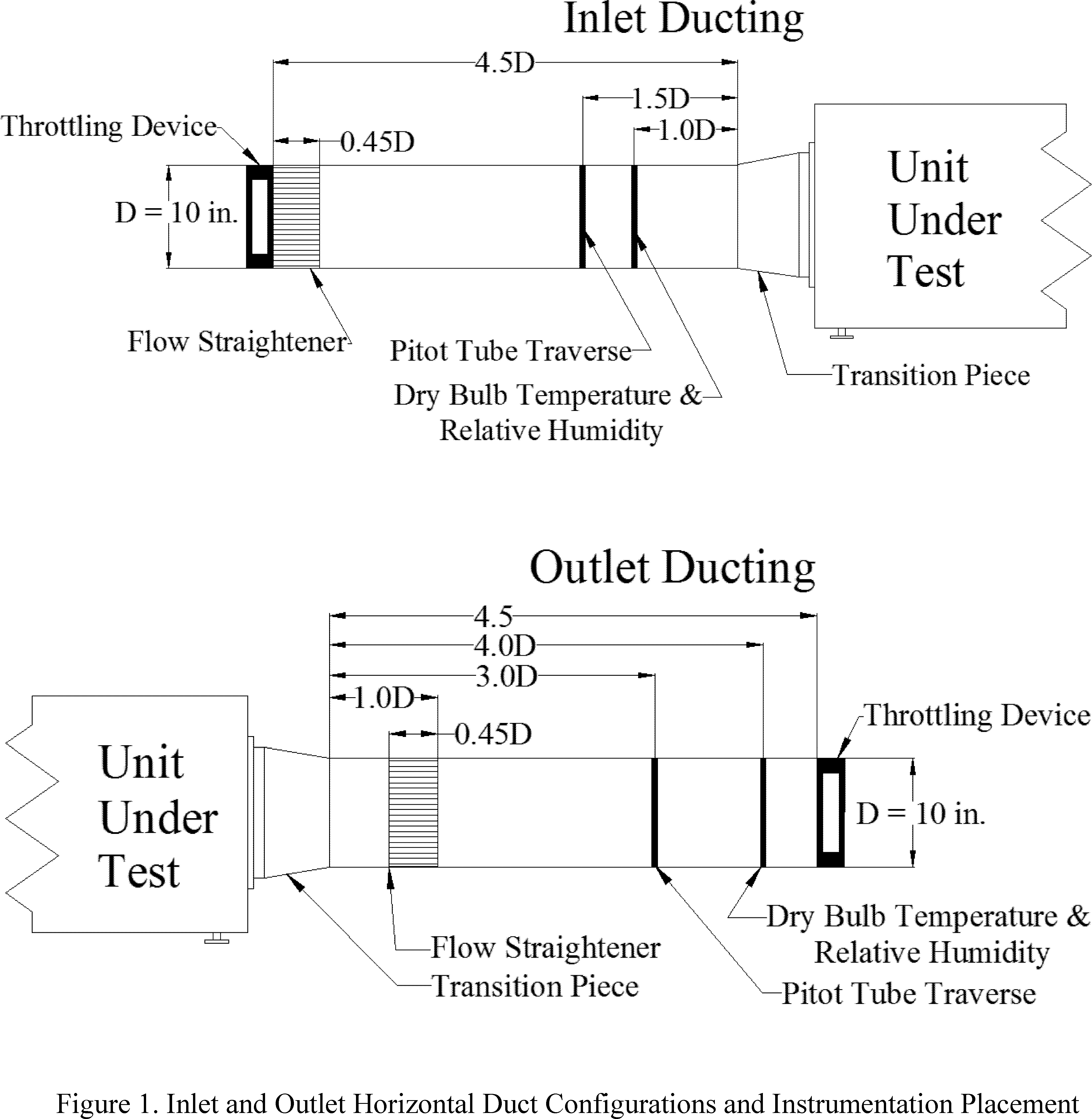
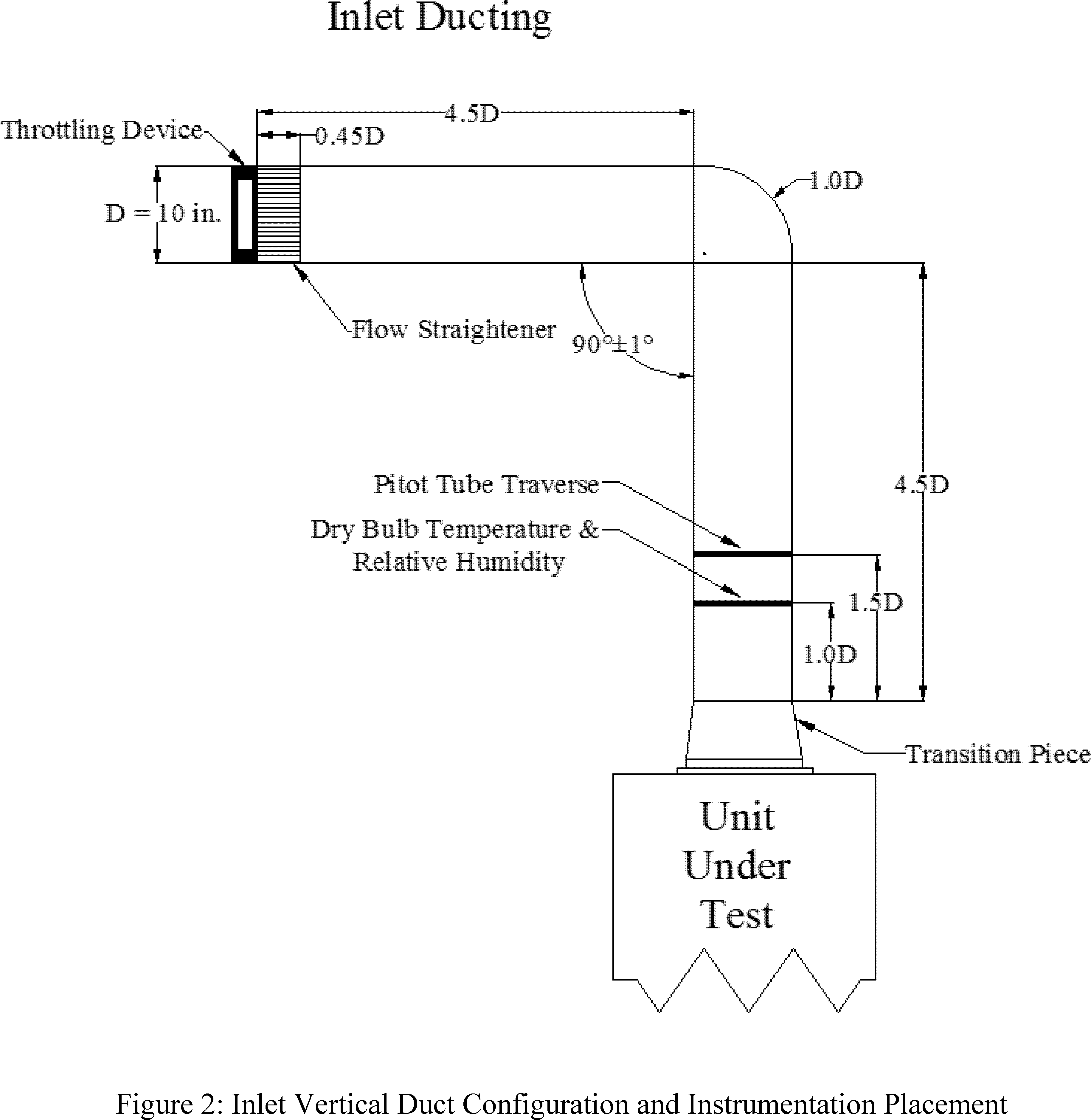
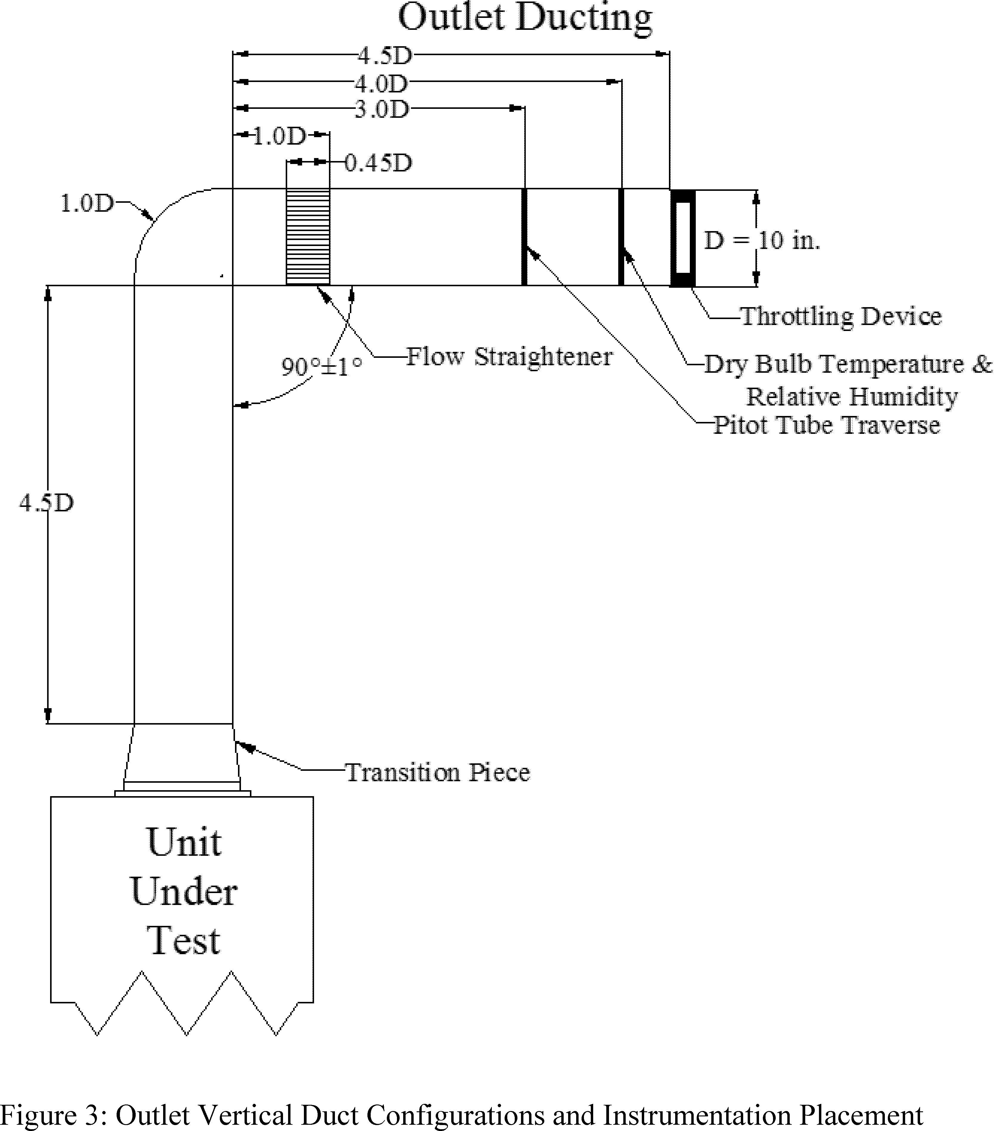
3.1.4 Recording and rounding. When testing either a portable dehumidifier or a whole-home dehumidifier, record measurements at the resolution of the test instrumentation. Record measurements for portable dehumidifiers and whole-home dehumidifiers other than refrigerant-desiccant dehumidifiers at intervals no greater than 10 minutes. Record measurements for refrigerant-desiccant dehumidifiers at intervals no greater than 1 minute. Round off calculations to the same number of significant digits as the previous step. Round the final product capacity, energy factor and integrated energy factor values to two decimal places, and for whole-home dehumidifiers, round the final product case volume to one decimal place.
3.2 Inactive mode and off mode.
3.2.1 Installation requirements. For the inactive mode and off mode testing, install the dehumidifier in accordance with Section 5, Paragraph 5.2 of IEC 62301 (incorporated by reference, see § 430.3), disregarding the provisions regarding batteries and the determination, classification, and testing of relevant modes.
3.2.2 Electrical energy supply.
3.2.2.1 Electrical supply. For the inactive mode and off mode testing, maintain the electrical supply voltage and frequency indicated in Section 7.1.3, “Standard Test Voltage,” of ANSI/AHAM DH-1 (incorporated by reference, see § 430.3). The electrical supply frequency shall be maintained ±1 percent.
3.2.2.2 Supply voltage waveform. For the inactive mode and off mode testing, maintain the electrical supply voltage waveform indicated in Section 4, Paragraph 4.3.2 of IEC 62301 (incorporated by reference, see § 430.3).
3.2.3 Inactive mode, off mode, and off-cycle mode wattmeter. The wattmeter used to measure inactive mode, off mode, and off-cycle mode power consumption must meet the requirements specified in Section 4, Paragraph 4.4 of IEC 62301 (incorporated by reference, see § 430.3).
3.2.4 Inactive mode and off mode ambient temperature. For inactive mode and off mode testing, maintain room ambient air temperature conditions as specified in Section 4, Paragraph 4.2 of IEC 62301 (incorporated by reference, see § 430.3).
3.3 Case dimensions for whole-home dehumidifiers. Measure case dimensions using equipment with a resolution of no more than 0.1 in.
4. Test Measurement
4.1 Dehumidification mode.
4.1.1 Portable dehumidifiers and whole-home dehumidifiers other than refrigerant-desiccant dehumidifiers. Measure the energy consumption in dehumidification mode, EDM, expressed in kilowatt-hours (kWh), the average relative humidity, Ht, either as measured using a relative humidity sensor or using the tables provided below when using an aspirating psychrometer, and the product capacity, Ct, expressed in pints per day (pints/day), in accordance with the test requirements specified in Section 7, “Capacity Test and Energy Consumption Test,” of ANSI/AHAM DH-1 (incorporated by reference, see § 430.3), except that the standard test conditions for portable dehumidifiers must be maintained at 65 °F ± 2.0 °F dry-bulb temperature and 56.6 °F ± 1.0 °F wet-bulb temperature, when recording conditions with an aspirating psychrometer, or 60 percent ± 2 percent relative humidity, when recording conditions with a relative humidity sensor. For whole-home dehumidifiers, conditions must be maintained at 73 °F ± 2.0 °F dry-bulb temperature and 63.6 °F ± 1.0 °F wet-bulb temperature, when recording conditions with an aspirating psychrometer, or 60 percent ± 2 percent relative humidity, when recording conditions with a relative humidity sensor. When using relative humidity and dry-bulb temperature sensors, for dehumidifiers with multiple process air intake grilles, average the measured relative humidities and average the measured dry-bulb temperatures to determine the overall intake air conditions.
Table 1—Relative Humidity as a Function of Dry-Bulb and Wet-Bulb Temperatures for Portable Dehumidifiers
| Wet-Bulb temperature ( °F) | Dry-Bulb temperature ( °F) | ||||||||||
|---|---|---|---|---|---|---|---|---|---|---|---|
| 64.5 | 64.6 | 64.7 | 64.8 | 64.9 | 65.0 | 65.1 | 65.2 | 65.3 | 65.4 | 65.5 | |
| 56.3 | 60.32 | 59.94 | 59.57 | 59.17 | 58.80 | 58.42 | 58.04 | 57.67 | 57.30 | 56.93 | 56.56 |
| 56.4 | 60.77 | 60.38 | 60.00 | 59.62 | 59.24 | 58.86 | 58.48 | 58.11 | 57.73 | 57.36 | 56.99 |
| 56.5 | 61.22 | 60.83 | 60.44 | 60.06 | 59.68 | 59.30 | 58.92 | 58.54 | 58.17 | 57.80 | 57.43 |
| 56.6 | 61.66 | 61.27 | 60.89 | 60.50 | 60.12 | 59.74 | 59.36 | 58.98 | 58.60 | 58.23 | 57.86 |
| 56.7 | 62.40 | 61.72 | 61.33 | 60.95 | 60.56 | 60.18 | 59.80 | 59.42 | 59.04 | 58.67 | 58.29 |
| 56.8 | 62.56 | 62.17 | 61.78 | 61.39 | 61.00 | 60.62 | 60.24 | 59.86 | 59.48 | 59.10 | 58.73 |
| 56.9 | 63.01 | 62.62 | 62.23 | 61.84 | 61.45 | 61.06 | 60.68 | 60.30 | 59.92 | 59.54 | 59.16 |
Table 2—Relative Humidity as a Function of Dry-Bulb and Wet-Bulb Temperatures for Whole-Home Dehumidifiers
| Wet-Bulb temperature ( °F) | Dry-Bulb temperature ( °F) | ||||||||||
|---|---|---|---|---|---|---|---|---|---|---|---|
| 72.5 | 72.6 | 72.7 | 72.8 | 72.9 | 73.0 | 73.1 | 73.2 | 73.3 | 73.4 | 73.5 | |
| 63.3 | 60.59 | 60.26 | 59.92 | 59.59 | 59.26 | 58.92 | 58.60 | 58.27 | 57.94 | 57.62 | 57.30 |
| 63.4 | 60.98 | 60.64 | 60.31 | 59.75 | 59.64 | 59.31 | 58.98 | 58.65 | 58.32 | 58.00 | 57.67 |
| 63.5 | 61.37 | 61.03 | 60.70 | 60.36 | 60.02 | 59.69 | 59.36 | 59.03 | 58.70 | 58.38 | 58.05 |
| 63.6 | 61.76 | 61.42 | 61.08 | 60.75 | 60.41 | 60.08 | 59.74 | 59.41 | 59.08 | 58.76 | 58.43 |
| 63.7 | 62.16 | 61.81 | 61.47 | 61.13 | 60.80 | 60.46 | 60.13 | 59.80 | 59.47 | 59.14 | 58.81 |
| 63.8 | 62.55 | 62.20 | 61.86 | 61.52 | 61.18 | 60.85 | 60.51 | 60.18 | 59.85 | 59.52 | 59.19 |
| 63.9 | 62.94 | 62.60 | 62.25 | 61.91 | 61.57 | 61.23 | 60.90 | 60.56 | 60.23 | 59.90 | 59.57 |
4.1.2 Refrigerant-desiccant dehumidifiers. Establish the testing conditions set forth in section 3.1.2 of this appendix. Measure the energy consumption, EDM, expressed in kWh, in accordance with the test requirements specified in Section 7, “Capacity Test and Energy Consumption Test,” of ANSI/AHAM DH-1 (incorporated by reference, see § 430.3), except that:
(1) individual readings of the standard test conditions at the air entering the process air inlet duct and the reactivation air inlet must be maintained within 73 °F ± 2.0 °F dry-bulb temperature and 60 percent ± 5 percent relative humidity and the arithmetic average of the inlet test conditions over the test period shall be maintained within 73 °F ± 0.5 °F dry-bulb temperature and 60 percent ± 2 percent relative humidity;
(2) the instructions for psychrometer placement do not apply;
(3) the data recorded must include dry-bulb temperatures, relative humidities, static pressures, velocity pressures in each duct, volumetric air flow rates, and the number of samples in the test period;
(4) the condensate collected during the test need not be weighed; and
(5) the calculations in Section 7.2.2, “Energy Factor Calculation,” of ANSI/AHAM DH-1 need not be performed. To perform the calculations in Section 7.1.7, “Calculation of Test Results,” of ANSI/AHAM DH-1: (1) replace “Condensate collected (lb)” and “mlb”, with the weight of condensate removed, W, as calculated in section 5.6 of this appendix; and (2) use the recorded relative humidities rather than the tables in section 4.1.1 of this appendix to determine average relative humidity.
4.2 Off-cycle mode. Establish the test conditions specified in section 3.1.1 or 3.1.2 of this appendix, but use the wattmeter specified in section 3.2.3 of this appendix. Begin the off-cycle mode test period immediately following the dehumidification mode test period. Adjust the setpoint higher than the ambient relative humidity to ensure the product will not enter dehumidification mode and begin the test when the compressor cycles off due to the change in setpoint. The off-cycle mode test period shall be 2 hours in duration, during which the power consumption is recorded at the same intervals as recorded for dehumidification mode testing. Measure and record the average off-cycle mode power of the dehumidifier, POC, in watts.
4.3 Inactive and off mode. Establish the testing conditions set forth in section 3.2 of this appendix, ensuring that the dehumidifier does not enter active mode during the test. For dehumidifiers that take some time to enter a stable state from a higher power state, as discussed in Section 5, Paragraph 5.1, Note 1 of IEC 62301 (incorporated by reference; see § 430.3), allow sufficient time for the dehumidifier to reach the lower power state before proceeding with the test measurement. Follow the test procedure specified in Section 5, Paragraph 5.3.2 of IEC 62301 for testing in each possible mode as described in sections 4.3.1 and 4.3.2 of this appendix.
4.3.1 If the dehumidifier has an inactive mode, as defined in section 2.10 of this appendix, but not an off mode, as defined in section 2.11 of this appendix, measure and record the average inactive mode power of the dehumidifier, PIA, in watts.
4.3.2 If the dehumidifier has an off mode, as defined in section 2.11 of this appendix, measure and record the average off mode power of the dehumidifier, POM, in watts.
4.4 Product case volume for whole-home dehumidifiers. Measure the maximum case length, DL, in inches, the maximum case width, DW, in inches, and the maximum height, DH, in inches, exclusive of any duct collar attachments or other external components.
5. Calculation of Derived Results From Test Measurements
5.1 Corrected relative humidity. Calculate the average relative humidity, for portable and whole-home dehumidifiers, corrected for barometric pressure variations as:
Hc,p = Ht × [1 + 0.0083 × (29.921 − B)]
Hc,wh = Ht × [1 + 0.0072 × (29.921 − B)]
Where:
Hc,p = portable dehumidifier average relative humidity from the test data in percent, corrected to the standard barometric pressure of 29.921 in. mercury (Hg);
Hc,wh = whole-home dehumidifier average relative humidity from the test data in percent, corrected to the standard barometric pressure of 29.921 in. Hg;
Ht = average relative humidity from the test data in percent; and
B = average barometric pressure during the test period in in. Hg.
5.2 Corrected product capacity. Calculate the product capacity, for portable and whole-home dehumidifiers, corrected for variations in temperature and relative humidity as:
Cr,p = Ct + 0.0352 × Ct × (65 − Tt) + 0.0169 × Ct × (60 − HC,p)
Cr,wh = Ct + 0.0344 × Ct × (73 − Tt) + 0.017 × Ct × (60 − HC,wh)
Where:
Cr,p = portable dehumidifiers product capacity in pints/day, corrected to standard rating conditions of 65 °F dry-bulb temperature and 60 percent relative humidity;
Cr,wh = whole-home dehumidifier product capacity in pints/day, corrected to standard rating conditions of 73 °F dry-bulb temperature and 60 percent relative humidity;
Ct = product capacity determined from test data in pints/day, as measured in section 4.1.1 of this appendix for portable and refrigerant-only whole-home dehumidifiers or calculated in section 5.6 of this appendix for refrigerant-desiccant whole-home dehumidifiers;
Tt = average dry-bulb temperature during the test period in °F;
HC,p = portable dehumidifier corrected relative humidity in percent, as determined in section 5.1 of this appendix; and
HC,wh = whole-home dehumidifier corrected relative humidity in percent, as determined in section 5.1 of this appendix.
5.3 Annual combined low-power mode energy consumption. Calculate the annual combined low-power mode energy consumption for dehumidifiers, ETLP, expressed in kWh per year:
ETLP = [(PIO × SIO) + (POC × SOC)] × K
Where:
PIO = PIA, dehumidifier inactive mode power, or POM, dehumidifier off mode power in watts, as measured in section 4.3 of this appendix;
POC = dehumidifier off-cycle mode power in watts, as measured in section 4.2 of this appendix;
SIO = 1,840.5 dehumidifier inactive mode or off mode annual hours;
SOC = 1,840.5 dehumidifier off-cycle mode annual hours; and
K = 0.001 kWh/Wh conversion factor for watt-hours to kWh.
5.4 Integrated energy factor. Calculate the integrated energy factor, IEF, expressed in L/kWh, rounded to two decimal places, according to the following:

Where:
Cr = corrected product capacity in pints per day, as determined in section 5.2 of this appendix;
t = test duration in hours;
EDM = energy consumption during the 6-hour dehumidification mode test in kWh, as measured in section 4.1 of this appendix;
ETLP = annual combined low-power mode energy consumption in kWh per year, as calculated in section 5.3 of this appendix;
1,095 = dehumidification mode annual hours, used to convert ETLP to combined low-power mode energy consumption per hour of dehumidification mode;
6 = hours per dehumidification mode test, used to convert annual combined low-power mode energy consumption per hour of dehumidification mode for integration with dehumidification mode energy consumption;
1.04 = the density of water in pounds per pint;
0.454 = the liters of water per pound of water; and
24 = the number of hours per day.
5.5 Absolute humidity for refrigerant-desiccant dehumidifiers. Calculate the absolute humidity of the air entering and leaving the refrigerant-desiccant dehumidifier in the process air stream, expressed in pounds of water per cubic foot of air, according to the following set of equations.
5.5.1 Temperature in Kelvin. The air dry-bulb temperature, in Kelvin, is:

Where:
TF = the measured dry-bulb temperature of the air in °F.
5.5.2 Water saturation pressure. The water saturation pressure, expressed in kilopascals (kPa), is:

Where:
TK = the calculated dry-bulb temperature of the air in K, calculated in section 5.5.1 of this appendix.
5.5.3 Vapor pressure. The water vapor pressure, expressed in kilopascals (kPa), is:

Where:
RH = percent relative humidity during the rating test period; and
Pws = water vapor saturation pressure in kPa, calculated in section 5.5.2 of this appendix.
5.5.4 Mixing humidity ratio. The mixing humidity ratio, the mass of water per mass of dry air, is:

Where:
Pw = water vapor pressure in kPa, calculated in section 5.5.3 of this appendix;
P = measured ambient barometric pressure in in. Hg;
3.386 = the conversion factor from in. Hg to kPa; and
0.62198 = the ratio of the molecular weight of water to the molecular weight of dry air.
5.5.5 Specific volume. The specific volume, expressed in feet cubed per pounds of dry air, is:

Where:
TK = dry-bulb temperature of the air in K, as calculated in section 5.5.1 of this appendix;
P = measured ambient barometric pressure in in. Hg;
Pw = water vapor pressure in kPa, calculated in section 5.5.3 of this appendix;
0.287055 = the specific gas constant for dry air in kPa times cubic meter per kg per K;
3.386 = the conversion factor from in. Hg to kPa; and
16.016 = the conversion factor from cubic meters per kilogram to cubic feet per pound.
5.5.6 Absolute humidity. The absolute humidity, expressed in pounds of water per cubic foot of air, is:

Where:
HR = the mixing humidity ratio, the mass of water per mass of dry air, as calculated in section 5.5.4 of this appendix; and
ν = the specific volume in cubic feet per pound of dry air, as calculated in section 5.5.5 of this appendix.
5.6 Product capacity for refrigerant-desiccant dehumidifiers. The weight of water removed during the test period, W, expressed in pounds is:
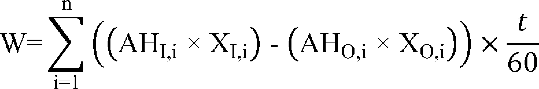
Where:
n = number of samples during the test period in section 4.1.1.2 of this appendix;
AHI,i = absolute humidity of the process air on the inlet side of the unit in pounds of water per cubic foot of dry air, as calculated for sample i in section 5.5.6 of this appendix;
XI,i = volumetric flow rate of the process air on the inlet side of the unit in cubic feet per minute, measured for sample i in section 4.1.1.2 of this appendix. Calculate the volumetric flow rate in accordance with Section 7.3, “Fan airflow rate at test conditions,” of ANSI/AMCA 210 (incorporated by reference, see § 430.3);
AHO,i = absolute humidity of the process air on the outlet side of the unit in pounds of water per cubic foot of dry air, as calculated for sample i in section 5.5.6 of this appendix;
XO,i = volumetric flow rate of the process air on the outlet side of the unit in cubic feet per minute, measured for sample i in section 4.1.1.2 of this appendix. Calculate the volumetric flow rate in accordance with Section 7.3, “Fan airflow rate at test conditions,” of ANSI/AMCA 210 (incorporated by reference, see § 430.3);
t = time interval in seconds between samples, with a maximum of 60; and
60 = conversion from minutes to seconds.
The capacity, Ct, expressed in pints/day, is:

Where:
24 = number of hours per day;
1.04 = density of water in pounds per pint; and
T = total test period time in hours.
Then correct the product capacity, Cr,wh, according to section 5.2 of this appendix.
5.7 Product case volume for whole-home dehumidifiers. The product case volume, V, in cubic feet, is:

Where:
DL = product case length in inches, measured in section 4.4 of this appendix;
DW = product case width in inches, measured in section 4.4 of this appendix;
DH = product case height in inches, measured in section 4.4 of this appendix; and
1,728 = conversion from cubic inches to cubic feet.
[80 FR 45826, July 31, 2015]
Appendix Y to Subpart B of Part 430 - Uniform Test Method for Measuring the Energy Consumption of Battery Chargers
Prior to November 16, 2016, manufacturers must make any representations regarding the energy consumption of battery chargers other than uninterruptible power supplies based upon results generated under this appendix or the previous version of this appendix as it appeared in the Code of Federal Regulations on January 1, 2016. On or after November 16, 2016, manufacturers must make any representations regarding the energy consumption of battery chargers other than uninterruptible power supplies based upon results generated under this appendix. On or after June 12, 2017, manufacturers must make any representations regarding the energy efficiency of uninterruptible power supplies based upon results generated under this appendix.
1. Scope
This appendix provides the test requirements used to measure the energy consumption of battery chargers operating at either DC or United States AC line voltage (115V at 60Hz). This appendix also provides the test requirements used to measure the energy efficiency of uninterruptible power supplies as defined in section 2 of this appendix that utilize the standardized National Electrical Manufacturer Association (NEMA) plug, 1-15P or 5-15P, as specified in ANSI/NEMA WD 6-2016 (incorporated by reference, see § 430.3) and have an AC output. This appendix does not provide a method for testing back-up battery chargers.
2. Definitions
The following definitions are for the purposes of explaining the terminology associated with the test method for measuring battery charger energy consumption.[1]
2.1. Active mode or charge mode is the state in which the battery charger system is connected to the main electricity supply, and the battery charger is delivering current, equalizing the cells, and performing other one-time or limited-time functions in order to bring the battery to a fully charged state.
2.2. Active power or real power (P) means the average power consumed by a unit. For a two terminal device with current and voltage waveforms i(t) and v(t), which are periodic with period T, the real or active power P is:

2.3. Ambient temperature is the temperature of the ambient air immediately surrounding the unit under test.
2.4. Apparent power (S) is the product of root-mean-square (RMS) voltage and RMS current in volt-amperes (VA).
2.5. Batch charger is a battery charger that charges two or more identical batteries simultaneously in a series, parallel, series-parallel, or parallel-series configuration. A batch charger does not have separate voltage or current regulation, nor does it have any separate indicators for each battery in the batch. When testing a batch charger, the term “battery” is understood to mean, collectively, all the batteries in the batch that are charged together. A charger can be both a batch charger and a multi-port charger or multi-voltage charger.
2.6. Battery or battery pack is an assembly of one or more rechargeable cells and any integral protective circuitry intended to provide electrical energy to a consumer product, and may be in one of the following forms:
(a) Detachable battery (a battery that is contained in a separate enclosure from the consumer product and is intended to be removed or disconnected from the consumer product for recharging); or
(b) integral battery (a battery that is contained within the consumer product and is not removed from the consumer product for charging purposes). The word “intended” in this context refers to the whether a battery has been designed in such a way as to permit its removal or disconnection from its associated consumer product.
2.7. Battery energy is the energy, in watt-hours, delivered by the battery under the specified discharge conditions in the test procedure.
2.8. Battery maintenance mode or maintenance mode is the mode of operation when the battery charger is connected to the main electricity supply and the battery is fully charged, but is still connected to the charger.
2.9. Battery rest period is a period of time between discharge and charge or between charge and discharge, during which the battery is resting in an open-circuit state in ambient air.
2.10. C-Rate (C) is the rate of charge or discharge, calculated by dividing the charge or discharge current by the nameplate battery charge capacity of the battery.
2.11. Cradle is an electrical interface between an integral battery product and the rest of the battery charger designed to hold the product between uses.
2.12. Energy storage system is a system consisting of single or multiple devices designed to provide power to the UPS inverter circuitry.
2.13. Equalization is a process whereby a battery is overcharged, beyond what would be considered “normal” charge return, so that cells can be balanced, electrolyte mixed, and plate sulfation removed.
2.14. Instructions or manufacturer's instructions means the documentation packaged with a product in printed or electronic form and any information about the product listed on a Web site maintained by the manufacturer and accessible by the general public at the time of the test. It also includes any information on the packaging or on the product itself. “Instructions” also includes any service manuals or data sheets that the manufacturer offers to independent service technicians, whether printed or in electronic form.
2.15. Measured charge capacity of a battery is the product of the discharge current in amperes and the time in decimal hours required to reach the specified end-of-discharge voltage.
2.16. Manual on-off switch is a switch activated by the user to control power reaching the battery charger. This term does not apply to any mechanical, optical, or electronic switches that automatically disconnect mains power from the battery charger when a battery is removed from a cradle or charging base, or for products with non-detachable batteries that control power to the product itself.
2.17. Multi-port charger means a battery charger that charges two or more batteries (which may be identical or different) simultaneously. The batteries are not connected in series or in parallel but with each port having separate voltage and/or current regulation. If the charger has status indicators, each port has its own indicator(s). A charger can be both a batch charger and a multi-port charger if it is capable of charging two or more batches of batteries simultaneously and each batch has separate regulation and/or indicator(s).
2.18. Multi-voltage charger is a battery charger that, by design, can charge a variety of batteries (or batches of batteries, if also a batch charger) that are of different nameplate battery voltages. A multi-voltage charger can also be a multi-port charger if it can charge two or more batteries simultaneously with independent voltages and/or current regulation.
2.19. Normal mode is a mode of operation for a UPS in which:
(1) The AC input supply is within required tolerances and supplies the UPS,
(2) The energy storage system is being maintained at full charge or is under recharge, and
(3) The load connected to the UPS is within the UPS's specified power rating.
2.20. Off mode is the condition, applicable only to units with manual on-off switches, in which the battery charger:
(1) Is connected to the main electricity supply;
(2) Is not connected to the battery; and
(3) All manual on-off switches are turned off.
2.21. Nameplate battery voltage is specified by the battery manufacturer and typically printed on the label of the battery itself. If there are multiple batteries that are connected in series, the nameplate battery voltage of the batteries is the total voltage of the series configuration - that is, the nameplate voltage of each battery multiplied by the number of batteries connected in series. Connecting multiple batteries in parallel does not affect the nameplate battery voltage.
2.22. Nameplate battery charge capacity is the capacity, claimed by the battery manufacturer on a label or in instructions, that the battery can store, usually given in ampere-hours (Ah) or milliampere-hours (mAh) and typically printed on the label of the battery itself. If there are multiple batteries that are connected in parallel, the nameplate battery charge capacity of the batteries is the total charge capacity of the parallel configuration, that is, the nameplate charge capacity of each battery multiplied by the number of batteries connected in parallel. Connecting multiple batteries in series does not affect the nameplate charge capacity.
2.23. Nameplate battery energy capacity means the product (in watts-hours (Wh)) of the nameplate battery voltage and the nameplate battery charge capacity.
2.24. Reference test load is a load or a condition with a power factor of greater than 0.99 in which the AC output socket of the UPS delivers the active power (W) for which the UPS is rated.
2.25. Standby mode or no-battery mode means the condition in which:
(1) The battery charger is connected to the main electricity supply;
(2) The battery is not connected to the charger; and
(3) For battery chargers with manual on-off switches, all such switches are turned on.
2.26. Total harmonic distortion (THD), expressed as a percent, is the root mean square (RMS) value of an AC signal after the fundamental component is removed and interharmonic components are ignored, divided by the RMS value of the fundamental component.
2.27. Uninterruptible power supply or UPS means a battery charger consisting of a combination of convertors, switches and energy storage devices (such as batteries), constituting a power system for maintaining continuity of load power in case of input power failure.
2.27.1. Voltage and frequency dependent UPS or VFD UPS means a UPS that produces an AC output where the output voltage and frequency are dependent on the input voltage and frequency. This UPS architecture does not provide corrective functions like those in voltage independent and voltage and frequency independent systems.
Note to 2.27.1: VFD input dependency may be verified by performing the AC input failure test in section 6.2.2.7 of IEC 62040-3 Ed. 2.0 (incorporated by reference, see § 430.3) and observing that, at a minimum, the UPS switches from normal mode of operation to battery power while the input is interrupted.
2.27.2. Voltage and frequency independent UPS or VFI UPS means a UPS where the device remains in normal mode producing an AC output voltage and frequency that is independent of input voltage and frequency variations and protects the load against adverse effects from such variations without depleting the stored energy source.
Note to 2.27.2: VFI input dependency may be verified by performing the steady state input voltage tolerance test and the input frequency tolerance test in sections 6.4.1.1 and 6.4.1.2 of IEC 62040-3 Ed. 2.0 (incorporated by reference, see § 430.3) respectively and observing that, at a minimum, the UPS produces an output voltage and frequency within the specified output range when the input voltage is varied by ±10% of the rated input voltage and the input frequency is varied by ±2% of the rated input frequency.
2.27.3. Voltage independent UPS or VI UPS means a UPS that produces an AC output within a specific tolerance band that is independent of under-voltage or over-voltage variations in the input voltage without depleting the stored energy source. The output frequency of a VI UPS is dependent on the input frequency, similar to a voltage and frequency dependent system.
Note to 2.27.3: VI input dependency may be verified by performing the steady state input voltage tolerance test in section 6.4.1.1 of IEC 62040-3 Ed. 2.0 (incorporated by reference, see § 430.3) and ensuring that the UPS remains in normal mode with the output voltage within the specified output range when the input voltage is varied by ±10% of the rated input voltage.
2.28. Unit under test (UUT) in this appendix refers to the combination of the battery charger and battery being tested.
3. Testing Requirements for all Battery Chargers Other Than Uninterruptible Power Supplies
3.1. Standard Test Conditions
3.1.1 General
The values that may be measured or calculated during the conduct of this test procedure have been summarized for easy reference in Table 3.1.1. of this appendix.
Table 3.1.1 - List of Measured or Calculated Values
| Name of measured or
calculated value |
Reference |
|---|---|
| 1. Duration of the charge and maintenance mode test | Section 3.3.2. |
| 2. Battery Discharge Energy | Section 3.3.8. |
| 3. Initial time and power (W) of the input current of connected battery | Section 3.3.6. |
| 4. Active and Maintenance Mode Energy Consumption | Section 3.3.6. |
| 5. Maintenance Mode Power | Section 3.3.9. |
| 6. 24 Hour Energy Consumption | Section 3.3.10. |
| 7. Standby Mode Power | Section 3.3.11. |
| 8. Off Mode Power | Section 3.3.12. |
| 9. Unit Energy Consumption, UEC (kWh/yr) | Section 3.3.13. |
3.1.2. Verifying Accuracy and Precision of Measuring Equipment
Any power measurement equipment utilized for testing must conform to the uncertainty and resolution requirements outlined in section 4, “General conditions for measurement”, as well as annexes B, “Notes on the measurement of low power modes”, and D, “Determination of uncertainty of measurement”, of IEC 62301 (incorporated by reference, see § 430.3).
3.1.3. Setting Up the Test Room
All tests, battery conditioning, and battery rest periods shall be carried out in a room with an air speed immediately surrounding the UUT of ≤0.5 m/s. The ambient temperature shall be maintained at 20 °C ± 5 °C throughout the test. There shall be no intentional cooling of the UUT such as by use of separately powered fans, air conditioners, or heat sinks. The UUT shall be conditioned, rested, and tested on a thermally non-conductive surface. When not undergoing active testing, batteries shall be stored at 20 °C ± 5 °C.
3.1.4. Verifying the UUT's Input Voltage and Input Frequency
(a) If the UUT is intended for operation on AC line-voltage input in the United States, it shall be tested at 115 V at 60 Hz. If the UUT is intended for operation on AC line-voltage input but cannot be operated at 115 V at 60 Hz, it shall not be tested.
(b) If a charger is powered by a low-voltage DC or AC input, and the manufacturer packages the charger with a wall adapter, sells, or recommends an optional wall adapter capable of providing that low voltage input, then the charger shall be tested using that wall adapter and the input reference source shall be 115 V at 60 Hz. If the wall adapter cannot be operated with AC input voltage at 115 V at 60 Hz, the charger shall not be tested.
(c) If the UUT is designed for operation only on DC input voltage and the provisions of section 3.1.4(b) of this appendix do not apply, it shall be tested with one of the following input voltages: 5.0 V DC for products drawing power from a computer USB port or the midpoint of the rated input voltage range for all other products. The input voltage shall be within ±1 percent of the above specified voltage.
(d) If the input voltage is AC, the input frequency shall be within ±1 percent of the specified frequency. The THD of the input voltage shall be ≤2 percent, up to and including the 13th harmonic. The crest factor of the input voltage shall be between 1.34 and 1.49.
(e) If the input voltage is DC, the AC ripple voltage (RMS) shall be:
(1) ≤0.2 V for DC voltages up to 10 V; or
(2) ≤2 percent of the DC voltage for DC voltages over 10 V.
3.2. Unit Under Test Setup Requirements
3.2.1. General Setup
(a) The battery charger system shall be prepared and set up in accordance with the manufacturer's instructions, except where those instructions conflict with the requirements of this test procedure. If no instructions are given, then factory or “default” settings shall be used, or where there are no indications of such settings, the UUT shall be tested in the condition as it would be supplied to an end user.
(b) If the battery charger has user controls to select from two or more charge rates (such as regular or fast charge) or different charge currents, the test shall be conducted at the fastest charge rate that is recommended by the manufacturer for everyday use, or, failing any explicit recommendation, the factory-default charge rate. If the charger has user controls for selecting special charge cycles that are recommended only for occasional use to preserve battery health, such as equalization charge, removing memory, or battery conditioning, these modes are not required to be tested. The settings of the controls shall be listed in the report for each test.
3.2.2. Selection and Treatment of the Battery Charger
The UUT, including the battery charger and its associated battery, shall be new products of the type and condition that would be sold to a customer. If the battery is lead-acid chemistry and the battery is to be stored for more than 24 hours between its initial acquisition and testing, the battery shall be charged before such storage.
3.2.3. Selection of Batteries To Use for Testing
(a) For chargers with integral batteries, the battery packaged with the charger shall be used for testing. For chargers with detachable batteries, the battery or batteries to be used for testing will vary depending on whether there are any batteries packaged with the battery charger.
(1) If batteries are packaged with the charger, batteries for testing shall be selected from the batteries packaged with the battery charger, according to the procedure in section 3.2.3(b) of this appendix.
(2) If no batteries are packaged with the charger, but the instructions specify or recommend batteries for use with the charger, batteries for testing shall be selected from those recommended or specified in the instructions, according to the procedure in section 3.2.3(b) of this appendix.
(3) If no batteries are packaged with the charger and the instructions do not specify or recommend batteries for use with the charger, batteries for testing shall be selected from any that are suitable for use with the charger, according to the procedure in section 3.2.3(b) of this appendix.
(b)
(1) From the detachable batteries specified above, use Table 3.2.1 of this appendix to select the batteries to be used for testing, depending on the type of battery charger being tested. The battery charger types represented by the rows in the table are mutually exclusive. Find the single applicable row for the UUT, and test according to those requirements. Select only the single battery configuration specified for the battery charger type in Table 3.2.1 of this appendix.
(2) If the battery selection criteria specified in Table 3.2.1 of this appendix results in two or more batteries or configurations of batteries of different chemistries, but with equal voltage and capacity ratings, determine the maintenance mode power, as specified in section 3.3.9 of this appendix, for each of the batteries or configurations of batteries, and select for testing the battery or configuration of batteries with the highest maintenance mode power.
(c) A charger is considered as:
(1) Single-capacity if all associated batteries have the same nameplate battery charge capacity (see definition) and, if it is a batch charger, all configurations of the batteries have the same nameplate battery charge capacity.
(2) Multi-capacity if there are associated batteries or configurations of batteries that have different nameplate battery charge capacities.
(d) The selected battery or batteries will be referred to as the “test battery” and will be used through the remainder of this test procedure.
Table 3.2.1 - Battery Selection for Testing
| Type of charger | Tests to perform | ||
|---|---|---|---|
| Multi-voltage | Multi-port | Multi-capacity | Battery selection
(from all configurations of all associated batteries) |
| No | No | No | Any associated battery. |
| No | No | Yes | Highest charge capacity battery. |
| No | Yes | Yes or No | Use all ports. Use the maximum number of identical batteries with the highest nameplate battery charge capacity that the charger can accommodate. |
| Yes | No | No | Highest voltage battery. |
| Yes | Yes to either or both | Use all ports. Use the battery or configuration of batteries with the highest individual voltage. If multiple batteries meet this criteria, then use the battery or configuration of batteries with the highest total nameplate battery charge capacity at the highest individual voltage. | |
3.2.4. Limiting Other Non-Battery-Charger Functions
(a) If the battery charger or product containing the battery charger does not have any additional functions unrelated to battery charging, this subsection may be skipped.
(b) Any optional functions controlled by the user and not associated with the battery charging process (e.g., the answering machine in a cordless telephone charging base) shall be switched off. If it is not possible to switch such functions off, they shall be set to their lowest power-consuming mode during the test.
(c) If the battery charger takes any physically separate connectors or cables not required for battery charging but associated with its other functionality (such as phone lines, serial or USB connections, Ethernet, cable TV lines, etc.), these connectors or cables shall be left disconnected during the testing.
(d) Any manual on-off switches specifically associated with the battery charging process shall be switched on for the duration of the charge, maintenance, and no-battery mode tests, and switched off for the off mode test.
3.2.5. Accessing the Battery for the Test
(a) The technician may need to disassemble the end-use product or battery charger to gain access to the battery terminals for the Battery Discharge Energy Test in section 3.3.8 of this appendix. If the battery terminals are not clearly labeled, the technician shall use a voltmeter to identify the positive and negative terminals. These terminals will be the ones that give the largest voltage difference and are able to deliver significant current (0.2 C or 1/hr) into a load.
(b) All conductors used for contacting the battery must be cleaned and burnished prior to connecting in order to decrease voltage drops and achieve consistent results.
(c) Manufacturer's instructions for disassembly shall be followed, except those instructions that:
(1) Lead to any permanent alteration of the battery charger circuitry or function;
(2) Could alter the energy consumption of the battery charger compared to that experienced by a user during typical use, e.g., due to changes in the airflow through the enclosure of the UUT; or
(3) Conflict requirements of this test procedure.
(d) Care shall be taken by the technician during disassembly to follow appropriate safety precautions. If the functionality of the device or its safety features is compromised, the product shall be discarded after testing.
(e) Some products may include protective circuitry between the battery cells and the remainder of the device. If the manufacturer provides a description for accessing the connections at the output of the protective circuitry, these connections shall be used to discharge the battery and measure the discharge energy. The energy consumed by the protective circuitry during discharge shall not be measured or credited as battery energy.
(f) If the technician, despite diligent effort and use of the manufacturer's instructions, encounters any of the following conditions noted immediately below, the Battery Discharge Energy and the Charging and Maintenance Mode Energy shall be reported as “Not Applicable”:
(1) Inability to access the battery terminals;
(2) Access to the battery terminals destroys charger functionality; or
(3) Inability to draw current from the test battery.
3.2.6. Determining Charge Capacity for Batteries With No Rating
(a) If there is no rating for the battery charge capacity on the battery or in the instructions, then the technician shall determine a discharge current that meets the following requirements. The battery shall be fully charged and then discharged at this constant-current rate until it reaches the end-of-discharge voltage specified in Table 3.3.2 of this appendix. The discharge time must be not less than 4.5 hours nor more than 5 hours. In addition, the discharge test (section 3.3.8 of this appendix) (which may not be starting with a fully-charged battery) shall reach the end-of-discharge voltage within 5 hours. The same discharge current shall be used for both the preparations step (section 3.3.4 of this appendix) and the discharge test (section 3.3.8 of this appendix). The test report shall include the discharge current used and the resulting discharge times for both a fully-charged battery and for the discharge test.
(b) For this section, the battery is considered as “fully charged” when either: it has been charged by the UUT until an indicator on the UUT shows that the charge is complete; or it has been charged by a battery analyzer at a current not greater than the discharge current until the battery analyzer indicates that the battery is fully charged.
(c) When there is no capacity rating, a suitable discharge current must generally be determined by trial and error. Since the conditioning step does not require constant-current discharges, the trials themselves may also be counted as part of battery conditioning.
3.3. Test Measurement
The test sequence to measure the battery charger energy consumption is summarized in Table 3.3.1 of this appendix, and explained in detail in this appendix. Measurements shall be made under test conditions and with the equipment specified in sections 3.1 and 3.2 of this appendix.
Table 3.3.1 - Test Sequence
| Step/Description | Data taken? | Equipment needed | ||||
|---|---|---|---|---|---|---|
| Test
battery |
Charger | Battery
analyzer or constant- current load |
AC power meter | Thermometer
(for flooded lead-acid battery chargers only) |
||
| 1. Record general data on UUT; Section 3.3.1 | Yes | X | X | |||
| 2. Determine test duration; Section 3.3.2 | No | |||||
| 3. Battery conditioning; Section 3.3.3 | No | X | X | X | ||
| 4. Prepare battery for charge test; Section 3.3.4 | No | X | X | |||
| 5. Battery rest period; Section 3.3.5 | No | X | X | |||
| 6. Conduct Charge Mode and Battery Maintenance Mode Test; Section 3.3.6 | Yes | X | X | X | ||
| 7. Battery Rest Period; Section 3.3.7 | No | X | X | |||
| 8. Battery Discharge Energy Test; Section 3.3.8 | Yes | X | X | |||
| 9. Determining the Maintenance Mode Power; Section 3.3.9 | Yes | X | X | X | ||
| 10. Calculating the 24-Hour Energy Consumption; Section 3.3.10 | No | |||||
| 11. Standby Mode Test; Section 3.3.11 | Yes | X | X | |||
| 12. Off Mode Test; Section 3.3.12 | Yes | X | X | |||
3.3.1. Recording General Data on the UUT
The technician shall record:
(a) The manufacturer and model of the battery charger;
(b) The presence and status of any additional functions unrelated to battery charging;
(c) The manufacturer, model, and number of batteries in the test battery;
(d) The nameplate battery voltage of the test battery;
(e) The nameplate battery charge capacity of the test battery; and
(f) The nameplate battery charge energy of the test battery.
(g) The settings of the controls, if battery charger has user controls to select from two or more charge rates.
3.3.2. Determining the Duration of the Charge and Maintenance Mode Test
(a) The charging and maintenance mode test, described in detail in section 3.3.6 of this appendix, shall be 24 hours in length or longer, as determined by the items below. Proceed in order until a test duration is determined.
(1) If the battery charger has an indicator to show that the battery is fully charged, that indicator shall be used as follows: If the indicator shows that the battery is charged after 19 hours of charging, the test shall be terminated at 24 hours. Conversely, if the full-charge indication is not yet present after 19 hours of charging, the test shall continue until 5 hours after the indication is present.
(2) If there is no indicator, but the manufacturer's instructions indicate that charging this battery or this capacity of battery should be complete within 19 hours, the test shall be for 24 hours. If the instructions indicate that charging may take longer than 19 hours, the test shall be run for the longest estimated charge time plus 5 hours.
(3) If there is no indicator and no time estimate in the instructions, but the charging current is stated on the charger or in the instructions, calculate the test duration as the longer of 24 hours or:

(b) If none of the above applies, the duration of the test shall be 24 hours.
3.3.3. Battery Conditioning
(a) No conditioning is to be done on lithium-ion batteries. The test technician shall proceed directly to battery preparation, section 3.3.4 of this appendix, when testing chargers for these batteries.
(b) Products with integral batteries will have to be disassembled per the instructions in section 3.2.5 of this appendix, and the battery disconnected from the charger for discharging.
(c) Batteries of other chemistries that have not been previously cycled are to be conditioned by performing two charges and two discharges, followed by a charge, as below. No data need be recorded during battery conditioning.
(1) The test battery shall be fully charged for the duration specified in section 3.3.2 of this appendix or longer using the UUT.
(2) The test battery shall then be fully discharged using either:
(i) A battery analyzer at a rate not to exceed 1 C, until its average cell voltage under load reaches the end-of-discharge voltage specified in Table 3.3.2 of this appendix for the relevant battery chemistry; or
(ii) The UUT, until the UUT ceases operation due to low battery voltage.
(3) The test battery shall again be fully charged as in step (c)(1) of this section.
(4) The test battery shall again be fully discharged as per step (c)(2) of this section.
(5) The test battery shall be again fully charged as in step (c)(1) of this section.
(d) Batteries of chemistries, other than lithium-ion, that are known to have been through at least two previous full charge/discharge cycles shall only be charged once per step (c)(5), of this section.
3.3.4. Preparing the Battery for Charge Testing
Following any conditioning prior to beginning the battery charge test (section 3.3.6 of this appendix), the test battery shall be fully discharged for the duration specified in section 3.3.2 of this appendix, or longer using a battery analyzer.
3.3.5. Resting the Battery
The test battery shall be rested between preparation and the battery charge test. The rest period shall be at least one hour and not exceed 24 hours. For batteries with flooded cells, the electrolyte temperature shall be less than 30 °C before charging, even if the rest period must be extended longer than 24 hours.
3.3.6. Testing Charge Mode and Battery Maintenance Mode
(a) The Charge and Battery Maintenance Mode test measures the energy consumed during charge mode and some time spent in the maintenance mode of the UUT. Functions required for battery conditioning that happen only with some user-selected switch or other control shall not be included in this measurement. (The technician shall manually turn off any battery conditioning cycle or setting.) Regularly occurring battery conditioning or maintenance functions that are not controlled by the user will, by default, be incorporated into this measurement.
(b) During the measurement period, input power values to the UUT shall be recorded at least once every minute.
(1) If possible, the technician shall set the data logging system to record the average power during the sample interval. The total energy is computed as the sum of power samples (in watts) multiplied by the sample interval (in hours).
(2) If this setting is not possible, then the power analyzer shall be set to integrate or accumulate the input power over the measurement period and this result shall be used as the total energy.
(c) The technician shall follow these steps:
(1) Ensure that the user-controllable device functionality not associated with battery charging and any battery conditioning cycle or setting are turned off, as instructed in section 3.2.4 of this appendix;
(2) Ensure that the test battery used in this test has been conditioned, prepared, discharged, and rested as described in sections 3.3.3 through 3.3.5 of this appendix;
(3) Connect the data logging equipment to the battery charger;
(4) Record the start time of the measurement period, and begin logging the input power;
(5) Connect the test battery to the battery charger within 3 minutes of beginning logging. For integral battery products, connect the product to a cradle or wall adapter within 3 minutes of beginning logging;
(6) After the test battery is connected, record the initial time and power (W) of the input current to the UUT. These measurements shall be taken within the first 10 minutes of active charging;
(7) Record the input power for the duration of the “Charging and Maintenance Mode Test” period, as determined by section 3.3.2 of this appendix. The actual time that power is connected to the UUT shall be within ±5 minutes of the specified period; and
(8) Disconnect power to the UUT, terminate data logging, and record the final time.
3.3.7. Resting the Battery
The test battery shall be rested between charging and discharging. The rest period shall be at least 1 hour and not more than 4 hours, with an exception for flooded cells. For batteries with flooded cells, the electrolyte temperature shall be less than 30 °C before charging, even if the rest period must be extended beyond 4 hours.
3.3.8. Battery Discharge Energy Test
(a) If multiple batteries were charged simultaneously, the discharge energy is the sum of the discharge energies of all the batteries.
(1) For a multi-port charger, batteries that were charged in separate ports shall be discharged independently.
(2) For a batch charger, batteries that were charged as a group may be discharged individually, as a group, or in sub-groups connected in series and/or parallel. The position of each battery with respect to the other batteries need not be maintained.
(b) During discharge, the battery voltage and discharge current shall be sampled and recorded at least once per minute. The values recorded may be average or instantaneous values.
(c) For this test, the technician shall follow these steps:
(1) Ensure that the test battery has been charged by the UUT and rested according to the procedures above.
(2) Set the battery analyzer for a constant discharge rate and the end-of-discharge voltage in Table 3.3.2 of this appendix for the relevant battery chemistry.
(3) Connect the test battery to the analyzer and begin recording the voltage, current, and wattage, if available from the battery analyzer. When the end-of-discharge voltage is reached or the UUT circuitry terminates the discharge, the test battery shall be returned to an open-circuit condition. If current continues to be drawn from the test battery after the end-of-discharge condition is first reached, this additional energy is not to be counted in the battery discharge energy.
(d) If not available from the battery analyzer, the battery discharge energy (in watt-hours) is calculated by multiplying the voltage (in volts), current (in amperes), and sample period (in hours) for each sample, and then summing over all sample periods until the end-of-discharge voltage is reached.
3.3.9. Determining the Maintenance Mode Power
After the measurement period is complete, the technician shall determine the average maintenance mode power consumption by examining the power-versus-time data from the charge and maintenance test and:
(a) If the maintenance mode power is cyclic or shows periodic pulses, compute the average power over a time period that spans a whole number of cycles and includes at least the last 4 hours.
(b) Otherwise, calculate the average power value over the last 4 hours.
3.3.10. Determining the 24-Hour Energy Consumption
The accumulated energy or the average input power, integrated over the test period from the charge and maintenance mode test, shall be used to calculate 24-hour energy consumption.
Table 3.3.2 - Required Battery Discharge Rates and End-of-Discharge Battery Voltages
| Battery chemistry | Discharge rate
(C) |
End-of-discharge voltage *
(volts per cell) |
|---|---|---|
| Valve-Regulated Lead Acid (VRLA) | 0.2 | 1.75 |
| Flooded Lead Acid | 0.2 | 1.70 |
| Nickel Cadmium (NiCd) | 0.2 | 1.0 |
| Nickel Metal Hydride (NiMH) | 0.2 | 1.0 |
| Lithium Ion (Li-Ion) | 0.2 | 2.5 |
| Lithium Polymer | 0.2 | 2.5 |
| Rechargeable Alkaline | 0.2 | 0.9 |
| Nanophosphate Lithium Ion | 0.2 | 2.0 |
| Silver Zinc | 0.2 | 1.2 |
3.3.11. Standby Mode Energy Consumption Measurement
The standby mode measurement depends on the configuration of the battery charger, as follows.
(a) Conduct a measurement of standby power consumption while the battery charger is connected to the power source. Disconnect the battery from the charger, allow the charger to operate for at least 30 minutes, and record the power (i.e., watts) consumed as the time series integral of the power consumed over a 10-minute test period, divided by the period of measurement. If the battery charger has manual on-off switches, all must be turned on for the duration of the standby mode test.
(b) Standby mode may also apply to products with integral batteries. If the product uses a cradle and/or adapter for power conversion and charging, then “disconnecting the battery from the charger” will require disconnection of the end-use product, which contains the batteries. The other enclosures of the battery charging system will remain connected to the main electricity supply, and standby mode power consumption will equal that of the cradle and/or adapter alone.
(c) If the product is powered through a detachable AC power cord and contains integrated power conversion and charging circuitry, then only the cord will remain connected to mains, and standby mode power consumption will equal that of the AC power cord (i.e., zero watts).
(d) Finally, if the product contains integrated power conversion and charging circuitry but is powered through a non-detachable AC power cord or plug blades, then no part of the system will remain connected to mains, and standby mode measurement is not applicable.
3.3.12. Off Mode Energy Consumption Measurement
The off mode measurement depends on the configuration of the battery charger, as follows.
(a) If the battery charger has manual on-off switches, record a measurement of off mode energy consumption while the battery charger is connected to the power source. Remove the battery from the charger, allow the charger to operate for at least 30 minutes, and record the power (i.e., watts) consumed as the time series integral of the power consumed over a 10-minute test period, divided by the period of measurement, with all manual on-off switches turned off. If the battery charger does not have manual on-off switches, record that the off mode measurement is not applicable to this product.
(b) Off mode may also apply to products with integral batteries. If the product uses a cradle and/or adapter for power conversion and charging, then “disconnecting the battery from the charger” will require disconnection of the end-use product, which contains the batteries. The other enclosures of the battery charging system will remain connected to the main electricity supply, and off mode power consumption will equal that of the cradle and/or adapter alone.
(c) If the product is powered through a detachable AC power cord and contains integrated power conversion and charging circuitry, then only the cord will remain connected to mains, and off mode power consumption will equal that of the AC power cord (i.e., zero watts).
(d) Finally, if the product contains integrated power conversion and charging circuitry but is powered through a non-detachable AC power cord or plug blades, then no part of the system will remain connected to mains, and off mode measurement is not applicable.
3.3.13. Unit Energy Consumption Calculation
Unit energy consumption (UEC) shall be calculated for a battery charger using one of the two equations (equation (i) or equation (ii)) listed in this section. If a battery charger is tested and its charge duration as determined in section 3.3.2 of this appendix minus 5 hours is greater than the threshold charge time listed in table 3.3.3 of this appendix (i.e. (tcd − 5) * n > ta&m), equation (ii) shall be used to calculate UEC; otherwise a battery charger's UEC shall be calculated using equation (i).

Where:
E24 = 24-hour energy as determined in section 3.3.10 of this appendix,
Ebatt = Measured battery energy as determined in section 3.3.8 of this appendix,
Pm = Maintenance mode power as determined in section 3.3.9 of this appendix,
Psb = Standby mode power as determined in section 3.3.11 of this appendix,
Poff = Off mode power as determined in section 3.3.12 of this appendix,
tcd = Charge test duration as determined in section 3.3.2 of this appendix, and
ta&m, n, tsb , and toff, are constants used depending upon a device's product class and found in the following table:
Table 3.3.3 - Battery Charger Usage Profiles
| Product class | Hours per day *** | Charges
(n) |
Threshold
charge time * |
|||||
|---|---|---|---|---|---|---|---|---|
| Number | Description | Rated battery
energy (ebatt) ** |
Special
characteristic or battery voltage |
Active +
maintenance (ta&m) |
Standby
(tsb) |
Off
(toff) |
Number
per day |
Hours |
| 1 | Low-Energy | ≤5 Wh | Inductive Connection **** | 20.66 | 0.10 | 0.00 | 0.15 | 137.73 |
| 2 | Low-Energy, Low-Voltage | <100 Wh | <4 V | 7.82 | 5.29 | 0.00 | 0.54 | 14.48 |
| 3 | Low-Energy, Medium-Voltage | 4-10 V | 6.42 | 0.30 | 0.00 | 0.10 | 64.20 | |
| 4 | Low-Energy, High-Voltage | >10 V | 16.84 | 0.91 | 0.00 | 0.50 | 33.68 | |
| 5 | Medium-Energy, Low-Voltage | 100-3000 Wh | <20 V | 6.52 | 1.16 | 0.00 | 0.11 | 59.27 |
| 6 | Medium-Energy, High-Voltage | ≥20 V | 17.15 | 6.85 | 0.00 | 0.34 | 50.44 | |
| 7 | High-Energy | >3000 Wh | 8.14 | 7.30 | 0.00 | 0.32 | 25.44 | |
4. Testing Requirements for Uninterruptible Power Supplies
4.1. Standard Test Conditions
4.1.1. Measuring Equipment
(a) The power or energy meter must provide true root mean square (r. m. s) measurements of the active input and output measurements, with an uncertainty at full rated load of less than or equal to 0.5% at the 95% confidence level notwithstanding that voltage and current waveforms can include harmonic components. The meter must measure input and output values simultaneously.
(b) All measurement equipment used to conduct the tests must be calibrated within the measurement equipment manufacturer specified calibration period by a standard traceable to International System of Units such that measurements meet the uncertainty requirements specified in section 4.1.1(a) of this appendix.
4.1.2. Test Room Requirements
All portions of the test must be carried out in a room with an air speed immediately surrounding the UUT of ≤0.5 m/s in all directions. Maintain the ambient temperature in the range of 20.0 °C to 30.0 °C, including all inaccuracies and uncertainties introduced by the temperature measurement equipment, throughout the test. No intentional cooling of the UUT, such as by use of separately powered fans, air conditioners, or heat sinks, is permitted. Test the UUT on a thermally non-conductive surface.
4.1.3. Input Voltage and Input Frequency
The AC input voltage and frequency to the UPS during testing must be within 3 percent of the highest rated voltage and within 1 percent of the highest rated frequency of the device.
4.2. Unit Under Test Setup Requirements
4.2.1. General Setup
Configure the UPS according to Annex J.2 of IEC 62040-3 Ed. 2.0 (incorporated by reference, see § 430.3) with the following additional requirements:
(a) UPS Operating Mode Conditions. If the UPS can operate in two or more distinct normal modes as more than one UPS architecture, conduct the test in its lowest input dependency as well as in its highest input dependency mode where VFD represents the lowest possible input dependency, followed by VI and then VFI.
(b) Energy Storage System. The UPS must not be modified or adjusted to disable energy storage charging features. Minimize the transfer of energy to and from the energy storage system by ensuring the energy storage system is fully charged (at the start of testing) as follows:
(1) If the UUT has a battery charge indicator, charge the battery for 5 hours after the UUT has indicated that it is fully charged.
(2) If the UUT does not have a battery charge indicator but the user manual shipped with the UUT specifies a time to reach full charge, charge the battery for 5 hours longer than the time specified.
(3) If the UUT does not have a battery charge indicator or user manual instructions, charge the battery for 24 hours.
(c) DC output port(s). All DC output port(s) of the UUT must remain unloaded during testing.
4.2.2. Additional Features
(a) Any feature unrelated to maintaining the energy storage system at full charge or delivery of load power (e.g., LCD display) shall be switched off. If it is not possible to switch such features off, they shall be set to their lowest power-consuming mode during the test.
(b) If the UPS takes any physically separate connectors or cables not required for maintaining the energy storage system at full charge or delivery of load power but associated with other features (such as serial or USB connections, Ethernet, etc.), these connectors or cables shall be left disconnected during the test.
(c) Any manual on-off switches specifically associated with maintaining the energy storage system at full charge or delivery of load power shall be switched on for the duration of the test.
4.3. Test Measurement and Calculation
Efficiency can be calculated from either average power or accumulated energy.
4.3.1. Average Power Calculations
If efficiency calculation are to be made using average power, calculate the average power consumption (Pavg) by sampling the power at a rate of at least 1 sample per second and computing the arithmetic mean of all samples over the time period specified for each test as follows:
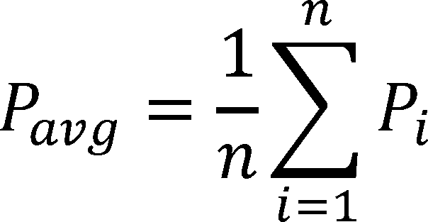
Where:
Pavg = average power
Pi = power measured during individual measurement (i)
n = total number of measurements
4.3.2. Steady State
Operate the UUT and the load for a sufficient length of time to reach steady state conditions. To determine if steady state conditions have been attained, perform the following steady state check, in which the difference between the two efficiency calculations must be less than 1 percent:
(a)
(1) Simultaneously measure the UUT's input and output power for at least 5 minutes, as specified in section 4.3.1 of this appendix, and record the average of each over the duration as Pavg_in and Pavg_out, respectively. Or,
(2) Simultaneously measure the UUT's input and output energy for at least 5 minutes and record the accumulation of each over the duration as Ein and Eout, respectively.
(b) Calculate the UUT's efficiency, Eff1, using one of the following two equations:

Where:
Eff is the UUT efficiency
Pavg_out is the average output power in watts
Pavg_in is the average input power in watts

Where:
Eff is the UUT efficiency
Eout is the accumulated output energy in watt-hours
Ein in the accumulated input energy in watt-hours
(c) Wait a minimum of 10 minutes.
(d) Repeat the steps listed in paragraphs (a) and (b) of section 4.3.2 of this appendix to calculate another efficiency value, Eff2.
(e) Determine if the product is at steady state using the following equation:
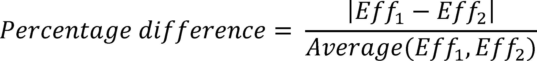
If the percentage difference of Eff1 and Eff2 as described in the equation, is less than 1 percent, the product is at steady state.
(f) If the percentage difference is greater than or equal to 1 percent, the product is not at steady state. Repeat the steps listed in paragraphs (c) to (e) of section 4.3.2 of this appendix until the product is at steady state.
4.3.3. Power Measurements and Efficiency Calculations
Measure input and output power of the UUT according to Section J.3 of Annex J of IEC 62040-3 Ed. 2.0 (incorporated by reference, see § 430.3), or measure the input and output energy of the UUT for efficiency calculations with the following exceptions:
(a) Test the UUT at the following reference test load conditions, in the following order: 100 percent, 75 percent, 50 percent, and 25 percent of the rated output power.
(b) Perform the test at each of the reference test loads by simultaneously measuring the UUT's input and output power in Watts (W), or input and output energy in Watt-Hours (Wh) over a 15 minute test period at a rate of at least 1 Hz. Calculate the efficiency for that reference load using one of the following two equations:

Where:
Effn% = the efficiency at reference test load n%
Pavg_out n% = the average output power at reference load n%
Pavg_in n% = the average input power at reference load n%

Where:
Effn% = the efficiency at reference test load n%
Eout n% = the accumulated output energy at reference load n%
Ein n% = the accumulated input energy at reference load n%
4.3.4. UUT Classification
Optional Test for determination of UPS architecture. Determine the UPS architecture by performing the tests specified in the definitions of VI, VFD, and VFI (sections 2.28.1 through 2.28.3 of this appendix).
4.3.5. Output Efficiency Calculation
(a) Use the load weightings from Table 4.3.1 to determine the average load adjusted efficiency as follows:

Where:
Effavg = the average load adjusted efficiency
tn% = the portion of time spent at reference test load n% as specified in Table 4.3.1
Eff |n% = the measured efficiency at reference test load n%
Table 4.3.1 - Load Weightings
| Rated output power
(W) |
UPS architecture | Portion of time spent at reference load | |||
|---|---|---|---|---|---|
| 25% | 50% | 75% | 100% | ||
| P ≤ 1500 W | VFD | 0.2 | 0.2 | 0.3 | 0.3 |
| VI or VFI | 0 * | 0.3 | 0.4 | 0.3 | |
| P > 1500 W | VFD, VI, or VFI | 0 * | 0.3 | 0.4 | 0.3 |
(b) Round the calculated efficiency value to one tenth of a percentage point.
[76 FR 31776, June 1, 2011, as amended at 81 FR 31842, May 20, 2016; 81 FR 42235, June 29, 2016; 81 FR 89822, Dec. 12, 2016]
Appendix Z to Subpart B of Part 430 - Uniform Test Method for Measuring the Energy Consumption of External Power Supplies
Starting on February 21, 2016, any representations made with respect to the energy use or efficiency of external power supplies must be made in accordance with the results of testing pursuant to this appendix. Prior to February 21, 2016, representations made with respect to the energy use or efficiency of external power supplies must be made in accordance with this appendix or Appendix Z as it appeared at 10 CFR part 430, subpart B, Appendix Z as contained in the 10 CFR parts 200 to 499 edition revised as of January 1, 2015. Because representations must be made in accordance with tests conducted pursuant to this appendix as of February 21, 2016, manufacturers may wish to begin using this test procedure as soon as possible.
1. Scope.
This appendix covers the test requirements used to measure the energy consumption of direct operation external power supplies and indirect operation Class A external power supplies subject to the energy conservation standards set forth at § 430.32(w)(1).
2. Definitions : The following definitions are for the purposes of understanding terminology associated with the test method for measuring external power supply energy consumption. For clarity on any other terminology used in the test method, please refer to IEC Standard 60050 or IEEE Standard 100. (Reference for guidance only, see § 430.4.)
a. Active mode means the mode of operation when the external power supply is connected to the main electricity supply and the output is (or “all outputs are” for a multiple-voltage external power supply) connected to a load (or “loads” for a multiple-voltage external power supply).
b. Active mode efficiency is the ratio, expressed as a percentage, of the total real output power produced by a power supply to the real input power required to produce it. (Reference for guidance only, see IEEE Standard 1515-2000, 4.3.1.1, § 430.4.)
c. Active power (P) (also real power) means the average power consumed by a unit. For a two terminal device with current and voltage waveforms i(t) and v(t) which are periodic with period T, the real or active power P is:

d. Ambient temperature means the temperature of the ambient air immediately surrounding the unit under test.
e. Apparent power (S) is the product of RMS voltage and RMS current (VA).
f. Average Active-Mode Efficiency means the average of the loading conditions (100 percent, 75 percent, 50 percent, and 25 percent of its nameplate output current) for which it can sustain the output current.
g. IEC 62301 means the test standard published by the International Electrotechnical Commission, titled “Household electrical appliances - Measurement of standby power,” Publication 62301 (Edition 2.0 2011-01) (incorporated by reference; see § 430.3).
h. Instantaneous power means the product of the instantaneous voltage and instantaneous current at a port (the terminal pair of a load).
i. Manual on-off switch is a switch activated by the user to control power reaching the device. This term does not apply to any mechanical, optical, or electronic switches that automatically disconnect mains power from the device when a load is disconnected from the device, or that control power to the load itself.
j. Minimum output current means the minimum current that must be drawn from an output bus for an external power supply to operate within its specifications.
k. Multiple-voltage external power supply means an external power supply that is designed to convert line voltage AC input into more than one simultaneous lower-voltage output.
l. Nameplate input frequency means the AC input frequency of the power supply as specified on the manufacturer's label on the power supply housing.
m. Nameplate input voltage means the AC input voltage of the power supply as specified on the manufacturer's label on the power supply housing.
n. Nameplate output current means the current output of the power supply as specified on the manufacturer's label on the power supply housing (either DC or AC) or, if absent from the housing, as provided by the manufacturer.
o. Nameplate output power means the power output of the power supply as specified on the manufacturer's label on the power supply housing or, if absent from the housing, as specified in documentation provided by the manufacturer.
p. Nameplate output voltage means the voltage output of the power supply as specified on the manufacturer's label on the power supply housing (either DC or AC).
q. No-load mode means the mode of operation when an external power supply is connected to the main electricity supply and the output is (or “all outputs are” for a multiple-voltage external power supply) not connected to a load (or “loads” for a multiple-voltage external power supply).
r. Off mode is the condition, applicable only to units with manual on-off switches, in which the external power supply is
(1) connected to the main electricity supply;
(2) the output is not connected to any load; and
(3) all manual on-off switches are turned off.
s. Output bus means any of the outputs of the power supply to which loads can be connected and from which power can be drawn, as opposed to signal connections used for communication.
t. Single-voltage external AC-AC power supply means an external power supply that is designed to convert line voltage AC input into lower voltage AC output and is able to convert to only one AC output voltage at a time.
u. Single-voltage external AC-DC power supply means an external power supply that is designed to convert line voltage AC input into lower-voltage DC output and is able to convert to only one DC output voltage at a time.
v. Standby mode means the condition in which the external power supply is in no-load mode and, for external power supplies with manual on-off switches, all such switches are turned on.
w. Switch-selectable single voltage external power supply means a single-voltage AC-AC or AC-DC power supply that allows users to choose from more than one output voltage.
x. Total harmonic distortion , expressed as a percentage, is the RMS value of an AC signal after the fundamental component is removed and interharmonic components are ignored, divided by the RMS value of the fundamental component. THD of current is defined as:

where In is the RMS value of the nth harmonic of the current signal.
y. True power factor (PF) is the ratio of the active power (P) consumed in watts to the apparent power (S), drawn in volt-amperes.

This definition of power factor includes the effect of both distortion and displacement.
z. Unit under test is the external power supply being tested.
3. Test Apparatus and General Instructions:
(a) Single-Voltage External Power Supply.
(i) Any power measurements recorded, as well as any power measurement equipment utilized for testing, shall conform to the uncertainty and resolution requirements outlined in Section 4, “General conditions for measurements,” as well as Annexes B, “Notes on the measurement of low power modes,” and D, “Determination of uncertainty of measurement,” of IEC 62301 (incorporated by reference; see § 430.3).
(ii) As is specified in IEC 62301 (incorporated by reference; see § 430.3), the tests shall be carried out in a room that has an air speed close to the unit under test (UUT) of ≤0.5 m/s. The ambient temperature shall be maintained at 20 ± 5 °C throughout the test. There shall be no intentional cooling of the UUT by use of separately powered fans, air conditioners, or heat sinks. The UUT shall be tested on a thermally non-conductive surface. Products intended for outdoor use may be tested at additional temperatures, provided those are in addition to the conditions specified above and are noted in a separate section on the test report.
(iii) If the UUT is intended for operation on AC line-voltage input in the United States, it shall be tested at 115 V at 60 Hz. If the UUT is intended for operation on AC line-voltage input but cannot be operated at 115 V at 60 Hz, it shall not be tested. The input voltage shall be within ±1 percent of the above specified voltage.
(iv) The input voltage source must be capable of delivering at least 10 times the nameplate input power of the UUT as is specified in IEEE 1515-2000 (Referenced for guidance only, see § 430.4). Regardless of the AC source type, the THD of the supply voltage when supplying the UUT in the specified mode must not exceed 2%, up to and including the 13th harmonic (as specified in IEC 62301). The peak value of the test voltage must be within 1.34 and 1.49 times its RMS value (as specified in IEC 62301 (incorporated by reference; see § 430.3)).
(v) Select all leads used in the test set-up as specified in Table B.2 - “Commonly used values for wire gages and related voltage drops” in IEEE 15152000.
(b) Multiple-Voltage External Power Supply. Unless otherwise specified, measurements shall be made under test conditions and with equipment specified below.
(i) Verifying Accuracy and Precision of Measuring Equipment
(A) Any power measurements recorded, as well as any power measurement equipment utilized for testing, must conform to the uncertainty and resolution requirements outlined in Section 4, “General conditions for measurements”, as well as Annexes B, “Notes on the measurement of low power modes”, and D, “Determination of uncertainty of measurement”, of IEC 62301 (incorporated by reference; see § 430.3).
(B) [Reserved]
(ii) Setting Up the Test Room
All tests shall be carried out in a room with an air speed immediately surrounding the UUT of ≤0.5 m/s. The ambient temperature shall be maintained at 20 °C ±5 °C throughout the test. There shall be no intentional cooling of the UUT such as by use of separately powered fans, air conditioners, or heat sinks. The UUT shall be conditioned, rested, and tested on a thermally non-conductive surface. A readily available material such as Styrofoam will be sufficient.
(iii) Verifying the UUT's Input Voltage and Input Frequency
(A) If the UUT is intended for operation on AC line-voltage input in the United States, it shall be tested at 115 V at 60 Hz. If the UUT is intended for operation on AC line-voltage input but cannot be operated at 115 V at 60 Hz, it shall not be tested. The input voltage shall be within ±1 percent of the above specified voltage.
(B) If the input voltage is AC, the input frequency shall be within ±1 percent of the specified frequency. The THD of the input voltage shall be ≤2 percent, up to and including the 13th harmonic. The crest factor of the input voltage shall be between 1.34 and 1.49.
4. Test Measurement:
(a) Single-Voltage External Power Supply
(i) Standby Mode and Active-Mode Measurement.
(A) Any built-in switch in the UUT controlling power flow to the AC input must be in the “on” position for this measurement, and note the existence of such a switch in the final test report. Test power supplies packaged for consumer use to power a product with the DC output cord supplied by the manufacturer. There are two options for connecting metering equipment to the output of this type of power supply: Cut the cord immediately adjacent to the DC output connector, or attach leads and measure the efficiency from the output connector itself. If the power supply is attached directly to the product that it is powering, cut the cord immediately adjacent to the powered product and connect DC measurement probes at that point. Any additional metering equipment such as voltmeters and/or ammeters used in conjunction with resistive or electronic loads must be connected directly to the end of the output cable of the UUT. If the product has more than two output wires, including those that are necessary for controlling the product, the manufacturer must supply a connection diagram or test fixture that will allow the testing laboratory to put the unit under test into active-mode. Figure 1 provides one illustration of how to set up an EPS for test; however, the actual test setup may vary pursuant to the requirements of this paragraph.

(B) External power supplies must be tested in their final, completed configuration in order to represent their measured efficiency on product labels or specification sheets. Although the same procedure may be used to test the efficiency of a bare circuit board power supply prior to its incorporation into a finished housing and the attachment of its DC output cord, the efficiency of the bare circuit board power supply may not be used to characterize the efficiency of the final product (once enclosed in a case and fitted with a DC output cord). For example, a power supply manufacturer or component manufacturer may wish to assess the efficiency of a design that it intends to provide to an OEM for incorporation into a finished external power supply, but these results may not be used to represent the efficiency of the finished external power supply.
(C) All single voltage external AC-DC power supplies have a nameplate output current. This is the value used to determine the four active-mode load conditions and the no load condition required by this test procedure. The UUT shall be tested at the following load conditions:
Table 1 - Loading Conditions for a Single-Voltage Unit Under Test
| Percentage of Nameplate Output Current | |
| Load Condition 1 | 100% of Nameplate Output Current ±2%. |
| Load Condition 2 | 75% of Nameplate Output Current ±2%. |
| Load Condition 3 | 50% of Nameplate Output Current ±2%. |
| Load Condition 4 | 25% of Nameplate Output Current ±2%. |
| Load Condition 5 | 0%. |
The 2% allowance is of nameplate output current, not of the calculated current value. For example, a UUT at Load Condition 3 may be tested in a range from 48% to 52% of rated output current. Additional load conditions may be selected at the technician's discretion, as described in IEEE 1515-2000 (Referenced for guidance only, see § 430.4), but are not required by this test procedure. For Loading Condition 5, place the UUT in no-load mode, disconnect any additional signal connections to the UUT, and measure input power.
1. Where the external power supply lists both an instantaneous and continuous output current, test the external power supply at the continuous condition only.
2. If an external power supply cannot sustain output at one or more of loading conditions 1-4 as specified in Table 1, test the external power supply only at the loading conditions for which it can sustain output. In these cases, the average active mode efficiency is the average of the loading conditions for which it can sustain the output.
(D) Test switch-selectable single-voltage external power supplies twice - once at the highest nameplate output voltage and once at the lowest.
(E) Test adaptive external power supplies twice - once at the highest achievable output voltage and once at the lowest.
(F) In order to load the power supply to produce all four active-mode load conditions, use a set of variable resistive or electronic loads. Although these loads may have different characteristics than the electronic loads power supplies are intended to power, they provide standardized and readily repeatable references for testing and product comparison. Note that resistive loads need not be measured precisely with an ohmmeter; simply adjust a variable resistor to the point where the ammeter confirms that the desired percentage of nameplate output current is flowing. For electronic loads, adjust the desired output current in constant current (CC) mode rather than adjusting the required output power in constant power (CP) mode.
(G) As noted in IEC 62301 (incorporated by reference; see § 430.3), instantaneous measurements are appropriate when power readings are stable in a particular load condition. Operate the UUT at 100% of nameplate current output for at least 30 minutes immediately prior to conducting efficiency measurements. After this warm-up period, monitor AC input power for a period of 5 minutes to assess the stability of the UUT. If the power level does not drift by more than 5% from the maximum value observed, the UUT is considered stable and the measurements should be recorded at the end of the 5-minute period. Measure subsequent load conditions under the same 5-minute stability parameters. Note that only one warm-up period of 30 minutes is required for each UUT at the beginning of the test procedure. If the AC input power is not stable over a 5-minute period, follow the guidelines established by IEC 62301 for measuring average power or accumulated energy over time for both AC input and DC output. Conduct efficiency measurements in sequence from Load Condition 1 to Load Condition 5 as indicated in Table 1. If testing of additional, optional load conditions is desired, that testing should be conducted in accordance with this test procedure and subsequent to completing the sequence described above.
(H) Calculate efficiency by dividing the UUT's measured DC output power at a given load condition by the true AC input power measured at that load condition. Calculate average efficiency as the arithmetic mean of the efficiency values calculated at Test Conditions 1, 2, 3, and 4 in Table 1, and record this value. Average efficiency for the UUT is a simple arithmetic average of active-mode efficiency values, and is not intended to represent weighted average efficiency, which would vary according to the duty cycle of the product powered by the UUT.
(I) Power consumption of the UUT at each Load Condition 1-4 is the difference between the DC output power (W) at that Load Condition and the AC input power (W) at that Load Condition. The power consumption of Load Condition 5 (no load) is equal to the AC input power (W) at that Load Condition.
(ii) Off-Mode Measurement - If the external power supply UUT incorporates manual on-off switches, place the UUT in off-mode, and measure and record its power consumption at “Load Condition 5” in Table 1. The measurement of the off-mode energy consumption must conform to the requirements specified in paragraph 4(a)(i) of this appendix, except that all manual on-off switches must be placed in the “off” position for the off-mode measurement. The UUT is considered stable if, over 5 minutes with samples taken at least once every second, the AC input power does not drift from the maximum value observed by more than 1 percent or 50 milliwatts, whichever is greater. Measure the off-mode power consumption of a switch-selectable single-voltage external power supply twice - once at the highest nameplate output voltage and once at the lowest.
(b) Multiple-Voltage External Power Supply - Power supplies must be tested with the output cord packaged with the unit for sale to the consumer, as it is considered part of the unit under test. There are two options for connecting metering equipment to the output of this type of power supply: cut the cord immediately adjacent to the output connector or attach leads and measure the efficiency from the output connector itself. If the power supply is attached directly to the product that it is powering, cut the cord immediately adjacent to the powered product and connect output measurement probes at that point. The tests should be conducted on the sets of output wires that constitute the output busses. If the product has additional wires, these should be left electrically disconnected unless they are necessary for controlling the product. In this case, the manufacturer shall supply a connection diagram or test fixture that will allow the testing laboratory to put the unit under test into active mode.
(i) Standby-Mode and Active-Mode Measurement - The measurement of the multiple-voltage external power supply standby mode (also no-load-mode) energy consumption and active-mode efficiency shall be as follows:
(A) Loading conditions and testing sequence.
(1) If the unit under test has on-off switches, all switches shall be placed in the “on” position. Loading criteria for multiple-voltage external power supplies shall be based on nameplate output current and not on nameplate output power because output voltage might not remain constant.
(2) The unit under test shall operate at 100 percent of nameplate current output for at least 30 minutes immediately before conducting efficiency measurements.
(3) After this warm-up period, the technician shall monitor AC input power for a period of 5 minutes to assess the stability of the unit under test. If the power level does not drift by more than 1 percent from the maximum value observed, the unit under test can be considered stable and measurements can be recorded at the end of the 5-minute period. Measurements at subsequent loading conditions, listed in Table 1, can then be conducted under the same 5-minute stability guidelines. Only one warm-up period of 30 minutes is required for each unit under test at the beginning of the test procedure.
(4) If AC input power is not stable over a 5-minute period, the technician shall follow the guidelines established by IEC Standard 62301 for measuring average power or accumulated energy over time for both input and output. (Reference for guidance only, see § 430.4).
(5) The unit under test shall be tested at the loading conditions listed in Table 1, derated per the proportional allocation method presented in the following section.
Table 1 - Loading Conditions for Unit Under Test
| Loading Condition 1 | 100% of Derated Nameplate Output Current ±2%. |
| Loading Condition 2 | 75% of Derated Nameplate Output Current ±2%. |
| Loading Condition 3 | 50% of Derated Nameplate Output Current ±2%. |
| Loading Condition 4 | 25% of Derated Nameplate Output Current ±2%. |
| Loading Condition 5 | 0%. |
(6) Input and output power measurements shall be conducted in sequence from Loading Condition 1 to Loading Condition 4, as indicated in Table 1. For Loading Condition 5, the unit under test shall be placed in no-load mode, any additional signal connections to the unit under test shall be disconnected, and input power shall be measured.
(B) Proportional allocation method for loading multiple-voltage external power supplies. For power supplies with multiple voltage busses, defining consistent loading criteria is difficult because each bus has its own nameplate output current. The sum of the power dissipated by each bus loaded to its nameplate output current may exceed the overall nameplate output power of the power supply. The following proportional allocation method must be used to provide consistent loading conditions for multiple-voltage external power supplies. For additional explanation, please refer to section 6.1.1 of the California Energy Commission's “Proposed Test Protocol for Calculating the Energy Efficiency of Internal Ac-Dc Power Supplies Revision 6.2,” November 2007.
(1) Consider a multiple-voltage power supply with N output busses, and nameplate output voltages V1, * * *, VN, corresponding output current ratings I1, * * *, IN, and a nameplate output power P. Calculate the derating factor D by dividing the power supply nameplate output power P by the sum of the nameplate output powers of the individual output busses, equal to the product of bus nameplate output voltage and current IiVi, as follows:

(2) If D ≥1, then loading every bus to its nameplate output current does not exceed the overall nameplate output power for the power supply. In this case, each output bus will simply be loaded to the percentages of its nameplate output current listed in Table 1. However, if D <1, it is an indication that loading each bus to its nameplate output current will exceed the overall nameplate output power for the power supply. In this case, and at each loading condition, each output bus will be loaded to the appropriate percentage of its nameplate output current listed in Table 1, multiplied by the derating factor D.
(C) Minimum output current requirements. Depending on their application, some multiple-voltage power supplies may require a minimum output current for each output bus of the power supply for correct operation. In these cases, ensure that the load current for each output at Loading Condition 4 in Table 1 is greater than the minimum output current requirement. Thus, if the test method's calculated load current for a given voltage bus is smaller than the minimum output current requirement, the minimum output current must be used to load the bus. This load current shall be properly recorded in any test report.
(D) Test loads. Active loads such as electronic loads or passive loads such as rheostats used for efficiency testing of the unit under test shall be able to maintain the required current loading set point for each output voltage within an accuracy of ±0.5 percent. If electronic load banks are used, their settings should be adjusted such that they provide a constant current load to the unit under test.
(E) Efficiency calculation. Efficiency shall be calculated by dividing the measured active output power of the unit under test at a given loading condition by the active AC input power measured at that loading condition. Efficiency shall be calculated at each Loading Condition (1, 2, 3, and 4, in Table 1) and be recorded separately.
(F) Power consumption calculation. Power consumption of the unit under test at Loading Conditions 1, 2, 3, and 4 is the difference between the active output power at that Loading Condition and the active AC input power at that Loading Condition. The power consumption of Loading Condition 5 (no-load) is equal to the AC active input power at that Loading Condition.
(ii) Off Mode Measurement - If the multiple-voltage external power supply unit under test incorporates any on-off switches, the unit under test shall be placed in off mode and its power consumption in off mode measured and recorded. The measurement of the off mode energy consumption shall conform to the requirements specified in paragraph (4)(b)(i) of this appendix. Note that the only loading condition that will be measured for off mode is “Loading Condition 5” in paragraph (A), “Loading conditions and testing sequence”, except that all manual on-off switches shall be placed in the off position for the measurement.
[71 FR 71366, Dec. 8, 2006, as amended at 74 FR 12066, Mar. 23, 2009; 74 FR 13334, Mar. 27, 2009; 76 FR 31782, June 1, 2011; 80 FR 51441, Aug. 25, 2015]
Appendix AA to Subpart B of Part 430—Uniform Test Method for Measuring the Energy Consumption of Furnace Fans
Any representation made after July 2, 2014 for energy consumption of furnace fans must be based upon results generated under this test procedure. Upon the compliance date(s) of any energy conservation standard(s) for furnace fans, use of the applicable provisions of this test procedure to demonstrate compliance with the energy conservation standard will also be required.
1. Scope. This appendix covers the test requirements used to measure the energy consumption of fans used in weatherized and non-weatherized gas furnaces, oil furnaces, electric furnaces, and modular blowers.
2. Definitions. Definitions include the definitions as specified in section 3 of ASHRAE 103-2007 (incorporated by reference, see § 430.3) and the following additional definitions, some of which supersede definitions found in ASHRAE 103-2007:
2.1. Active mode means the condition in which the product in which the furnace fan is integrated is connected to a power source and circulating air through ductwork.
2.2. Airflow-control settings are programmed or wired control system configurations that control a fan to achieve discrete, differing ranges of airflow—often designated for performing a specific function (e.g., cooling, heating, or constant circulation)—without manual adjustment other than interaction with a user-operable control such as a thermostat that meets the manufacturer specifications for installed-use. For the purposes of this appendix, manufacturer specifications for installed-use shall be found in the product literature shipped with the unit.
2.3. ASHRAE 103-2007 means ANSI/ASHRAE Standard 103-2007, published in 2007 by ASHRAE, approved by the American National Standards Institute (ANSI) on March 25, 2008, and entitled “Method of Testing for Annual Fuel Utilization Efficiency of Residential Central Furnaces and Boilers”. Only those sections of ASHRAE 103-2007 (incorporated by reference; see § 430.3) specifically referenced in this test procedure are part of this test procedure. In cases where there is a conflict, the language of the test procedure in this appendix takes precedence over ASHRAE 103-2007.
2.4. ANSI/ASHRAE Standard 41.1-1986 (RA 2006) means the test standard published in 1986, approved by ANSI on February 18, 1987, reaffirmed in 2006, and entitled “Standard Method for Temperature Measurement” (incorporated by reference; see § 430.3).
2.5. ASHRAE Standard 37-2009 means the test standard published in 2009 by ASHRAE entitled “Methods of Testing for Rating Unitary Air-Conditioning and Heat Pump Equipment” (incorporated by reference; see § 430.3).
2.6. Default airflow-control settings are the airflow-control settings specified for installed-use by the manufacturer. For the purposes of this appendix, manufacturer specifications for installed-use are those specifications provided for typical consumer installations in the product literature shipped with the product in which the furnace fan is installed. In instances where a manufacturer specifies multiple airflow-control settings for a given function to account for varying installation scenarios, the highest airflow-control setting specified for the given function shall be used for the procedures specified in this appendix.
2.7. External static pressure (ESP) means the difference between static pressures measured in the outlet duct and return air opening (or return air duct when used for testing) of the product in which the furnace fan is integrated.
2.8. Furnace fan means an electrically-powered device used in a consumer product for the purpose of circulating air through ductwork.
2.9. Modular blower means a product which only uses single-phase electric current, and which:
(a) Is designed to be the principal air circulation source for the living space of a residence;
(b) Is not contained within the same cabinet as a furnace or central air conditioner; and
(c) Is designed to be paired with HVAC products that have a heat input rate of less than 225,000 Btu per hour and cooling capacity less than 65,000 Btu per hour.
2.10. Off mode means the condition in which the product in which the furnace fan is integrated either is not connected to the power source or is connected to the power source but not energized.
2.11. Seasonal off switch means a switch on the product in which the furnace fan is integrated that, when activated, results in a measurable change in energy consumption between the standby and off modes.
2.12. Standby mode means the condition in which the product in which the furnace fan is integrated is connected to the power source, energized, but the furnace fan is not circulating air.
2.13. Thermal stack damper means a type of stack damper that opens only during the direct conversion of thermal energy of the stack gases.
3. Classifications. Classifications are as specified in section 4 of ASHRAE 103-2007 (incorporated by reference, see § 430.3).
4. Requirements. Requirements are as specified in section 5 of ASHRAE 103-2007 (incorporated by reference, see § 430.3). In addition, Fan Energy Rating (FER) of furnace fans shall be determined using test data and estimated national average operating hours pursuant to section 10.10 of this appendix.
5. Instruments. Instruments must be as specified in section 6, not including section 6.2, of ASHRAE 103-2007 (incorporated by reference, see § 430.3); and as specified in section 5.1 and 5.2 of this appendix.
5.1. Temperature. Temperature measuring instruments shall meet the provisions specified in section 5.1 of ASHRAE 37-2009 (incorporated by reference, see § 430.3) and shall be accurate to within 0.75 degree Fahrenheit (within 0.4 degrees Celsius).
5.1.1. Outlet Air Temperature Thermocouple Grid. Outlet air temperature shall be measured as described in section 8.2.1.5.5 of ASHRAE 103-2007 (incorporated by reference, see § 430.3) and illustrated in Figure 2 of ASHRAE 103-2007. Thermocouples shall be placed downstream of pressure taps used for external static pressure measurement.
5.2. Humidity. Air humidity shall be measured with a relative humidity sensor that is accurate to within 5% relative humidity. Air humidity shall be measured as close as possible to the inlet of the product in which the furnace fan is installed.
6. Apparatus. The apparatus used in conjunction with the furnace during the testing shall be as specified in section 7 of ASHRAE 103-2007 (incorporated by reference, see § 430.3) except for section 7.1, the second paragraph of section 7.2.2.2, section 7.2.2.5, and section 7.7, and as specified in sections 6.1, 6.2, 6.3,6.4, 6.5 and 6.6 of this appendix.
6.1. General. The product in which the furnace fan is integrated shall be installed in the test room in accordance with the product manufacturer's written instructions that are shipped with the product unless required otherwise by a specific provision of this appendix. The apparatus described in this section is used in conjunction with the product in which the furnace fan is integrated. Each piece of the apparatus shall conform to material and construction specifications and the reference standard cited. Test rooms containing equipment shall have suitable facilities for providing the utilities necessary for performance of the test and be able to maintain conditions within the limits specified.
6.2. Downflow furnaces. Install the internal section of vent pipe the same size as the flue collar for connecting the flue collar to the top of the unit, if not supplied by the manufacturer. Do not insulate the internal vent pipe during the jacket loss test (if conducted) described in section 8.6 of ASHRAE 103-2007 (incorporated by reference, see § 430.3) or the steady-state test described in section 9.1 of ASHRAE 103-2007. Do not insulate the internal vent pipe before the cool-down and heat-up tests described in sections 9.5 and 9.6, respectively, of ASHRAE 103-2007. If the vent pipe is surrounded by a metal jacket, do not insulate the metal jacket. Install a 5-ft test stack of the same cross sectional area or perimeter as the vent pipe above the top of the furnace. Tape or seal around the junction connecting the vent pipe and the 5-ft test stack. Insulate the 5-ft test stack with insulation having a minimum R-value of 7 and an outer layer of aluminum foil. (See Figure 3-E of ASHRAE 103-2007.)
6.3. Modular Blowers. A modular blower shall be equipped with the electric heat resistance kit that is likely to have the largest volume of retail sales with that particular basic model of modular blower.
6.4. Ducts and Plenums. Ducts and plenums shall be built to the geometrical specifications in section 7 of ASHRAE 103-2007. An apparatus for measuring external static pressure shall be integrated in the plenum and test duct as specified in sections 6.4, excluding specifications regarding the minimum length of the ducting and minimum distance between the external static pressure taps and product inlet and outlet, and 6.5 of ASHRAE 37-2009 (incorporated by reference, see § 430.3). External static pressure measuring instruments shall be placed between the furnace openings and any restrictions or elbows in the test plenums or ducts. For all test configurations, external static pressure taps shall be placed 18 inches from the outlet.
6.4.1. For tests conducted using a return air duct. Additional external static pressure taps shall be placed 12 inches from the product inlet. Pressure shall be directly measured as a differential pressure as depicted in Figure 8 of ASHRAE 37-2009 rather than determined by separately measuring inlet and outlet static pressure and subtracting the results.
6.4.2. For tests conducted without a return air duct. External static pressure shall be directly measured as the differential pressure between the outlet duct static pressure and the ambient static pressure as depicted in Figure 7a of ASHRAE 37-2009.
6.5. Air Filters. Air filters shall be removed.
6.6. Electrical Measurement. Only electrical input power to the furnace fan (and electric resistance heat kit for electric furnaces and modular blowers) shall be measured for the purposes of this appendix. Electrical input power to the furnace fan and electric resistance hate kit shall be sub-metered separately. Electrical input power to all other electricity-consuming components of the product in which the furnace fan is integrated shall not be included in the electrical input power measurements used in the FER calculation. If the procedures of this appendix are being conducted at the same time as another test that requires metering of components other than the furnace fan and electric resistance heat kit, the electrical input power to the furnace fan and electric resistance heat kit shall be sub-metered separately from one another and separately from other electrical input power measurements.
7. Test Conditions. The testing conditions shall be as specified in section 8, not including section 8.6.1.1, of ASHRAE 103-2007 (incorporated by reference, see § 430.3); and as specified in section 7.1 of this appendix.
7.1. Measurement of Jacket Surface Temperature (optional). The jacket of the furnace or boiler shall be subdivided into 6-inch squares when practical, and otherwise into 36-square-inch regions comprising 4 in. x 9 in. or 3 in. x 12 in. sections, and the surface temperature at the center of each square or section shall be determined with a surface thermocouple. The 36-square-inch areas shall be recorded in groups where the temperature differential of the 36-square-inch area is less than 10 °F for temperature up to 100 °F above room temperature and less than 20 °F for temperature more than 100 °F above room temperature. For forced air central furnaces, the circulating air blower compartment is considered as part of the duct system and no surface temperature measurement of the blower compartment needs to be recorded for the purpose of this test. For downflow furnaces, measure all cabinet surface temperatures of the heat exchanger and combustion section, including the bottom around the outlet duct, and the burner door, using the 36 square-inch thermocouple grid. The cabinet surface temperatures around the blower section do not need to be measured (see figure 3-E of ASHRAE 103-2007.)
8. Test Procedure. Testing and measurements shall be as specified in section 9 of ASHRAE 103-2007 (incorporated by reference, see § 430.3) except for sections 9.1.2.1, 9.3, 9.5.1.1, 9.5.1.2.1, 9.5.1.2.2, 9.5.2.1, and section 9.7.1; and as specified in sections 8.1 through 8.6 of this appendix.
8.1. Direct Measurement of Off-Cycle Losses Testing Method. [Reserved]
8.2. Measurement of Electrical Standby and Off Mode Power. [Reserved]
8.3. Steady-State Conditions for Gas and Oil Furnaces. Steady-state conditions are indicated by an external static pressure within the range shown in Table 1 and a temperature variation in three successive readings, taken 15 minutes apart, of not more than any of the following:
(a) 3 °F in the stack gas temperature for furnaces equipped with draft diverters;
(b) 5 °F in the stack gas temperature for furnaces equipped with either draft hoods, direct exhaust, or direct vent systems; and
(c) 1 °F in the flue gas temperature for condensing furnaces.
8.4. Steady-state Conditions for Electric Furnaces and Modular Blowers. Steady-state conditions are indicated by an external static pressure within the range shown in Table 1 and a temperature variation of not more than 5 °F in the outlet air temperature in four successive temperature readings taken 15 minutes apart.
8.5. Steady-State Conditions for Cold Flow Tests. For tests during which the burner or electric heating elements are turned off (i.e., cold flow tests), steady-state conditions are indicated by an external static pressure within the range shown in Table 1 and a variation in the difference between outlet temperature and ambient temperature of not more than 3 °F in three successive temperature readings taken 15 minutes apart.
8.6. Fan Energy Rating (FER) Test.
8.6.1. Initial FER test conditions and maximum airflow-control setting measurements. Measure the relative humidity (W) and dry bulb temperature (Tdb) of the test room.
8.6.1.1. Furnace fans for which the maximum airflow-control setting is not a default heating airflow-control setting. The main burner or electric heating elements shall be turned off. Adjust the external static pressure to within the range shown in Table 1 by symmetrically restricting the outlet of the test duct. Maintain these settings until steady-state conditions are attained as specified in section 8.3, 8.4, and 8.5 of this appendix. Measure furnace fan electrical input power (EMax), external static pressure (ESPMax), and outlet air temperature (TMax,Out).
8.6.1.2. Furnace fans for which the maximum airflow-control setting is a default heating airflow-control setting. Adjust the main burner or electric heating element controls to the default heat setting designated for the maximum airflow-control setting. Burner adjustments shall be made as specified by section 8.4.1 of ASHRAE 103-2007 (incorporated by reference, see § 430.3). Adjust the furnace fan controls to the maximum airflow-control setting. Adjust the external static to within the range shown in Table 1 by symmetrically restricting the outlet of the test duct. Maintain these settings until steady-state conditions are attained as specified in section 8.3, 8.4, and 8.5 of this appendix and the temperature rise (ΔTMax) is at least 18 °F. Measure furnace fan electrical input power (EMax), fuel or electric resistance heat kit input energy (QIN, Max), external static pressure (ESPMax), steady-state efficiency for this setting (EffySS, Max) as specified in sections 11.2 and 11.3 of ASHRAE 103-2007, outlet air temperature (TMax,Out), and temperature rise (ΔTMax)
Table 1—Required Minimum External Static Pressure in the Maximum Airflow-Control Setting by Installation Type
| Installation type | ESP (in. wc.) * |
|---|---|
| Units with an internal, factory-installed evaporator coil | 0.50-0.55 |
| Units designed to be paired with an evaporator coil, but without one installed | 0.65-0.70 |
| Mobile home | 0.30-0.35 |
Once the specified ESP has been achieved, the same outlet duct restrictions shall be used for the remainder of the furnace fan test.
8.6.2. Constant circulation airflow-control setting measurements. The main burner or electric heating elements shall be turned off. The furnace fan controls shall be adjusted to the default constant circulation airflow-control setting. If the manufacturer does not specify a constant circulation airflow-control setting, the lowest airflow-control setting shall be used. Maintain these settings until steady-state conditions are attained as specified in section 8.3, 8.4, and 8.5 of this appendix. Measure furnace fan electrical input power (ECirc) and external static pressure (ESPCirc).
8.6.3. Heating airflow-control setting measurements. For single-stage gas and oil furnaces, the burner shall be fired at the maximum heat input rate. For single-stage electric furnaces, the electric heating elements shall be energized at the maximum heat input rate. For multi-stage and modulating furnaces the reduced heat input rate settings shall be used. Burner adjustments shall be made as specified by section 8.4.1 of ASHRAE 103-2007 (incorporated by reference, see § 430.3). After the burner is activated and adjusted or the electric heating elements are energized, the furnace fan controls shall be adjusted to operate the fan in the default heat airflow-control setting. In instances where a manufacturer specifies multiple airflow-control settings for a given function to account for varying installation scenarios, the highest airflow-control setting specified for the given function shall be used. High heat and reduced heat shall be considered different functions for multi-stage heating units. Maintain these settings until steady-state conditions are attained as specified in section 8.3, 8.4, and 8.5 of this appendix and the temperature rise (ΔTHeat) is at least 18 °F. Measure furnace fan electrical input power (EHeat), external static pressure (ESPHeat), steady-state efficiency for this setting (EffySS) as specified in sections 11.2 and 11.3 of ASHRAE 103-2007, outlet air temperature (THeat, Out) and temperature rise (ΔTHeat).
9. Nomenclature. Nomenclature shall include the nomenclature specified in section 10 of ASHRAE 103-2007 (incorporated by reference, see § 430.3) and the following additional variables:
CH = annual furnace fan cooling hours
CCH = annual furnace fan constant-circulation hours
ECirc = furnace fan electrical consumption at the default constant-circulation airflow-control setting (or minimum airflow-control setting operating point if a default constant-circulation airflow-control setting is not specified), in watts
EHeat = furnace fan electrical consumption in the default heat airflow-control setting for single-stage heating products or the default low-heat setting for multi-stage heating products, in watts
EMax = furnace fan electrical consumption in the maximum airflow-control setting, in watts
ESPi = external static pressure, in inches water column, at time of the electrical power measurement in airflow-control setting i, where i can be “Circ” to represent constant-circulation (or minimum airflow) mode, “Heat” to represent heating mode, or “Max” to represent cooling (or maximum airflow) mode.
FER = fan energy rating, in watts/1000 cfm
HH = annual furnace fan heating operating hours
HCR = heating capacity ratio (nameplate reduced heat input capacity divided by nameplate maximum input heat capacity)
kref = physical descriptor characterizing the reference system
Tdb = dry bulb temperature of the test room, in °F
Ti, In = inlet air temperature at time of the electrical power measurement, in °F, in airflow-control setting i, where i can be “Circ” to represent constant-circulation (or minimum airflow) mode, “Heat” to represent heating mode, or “Max” to represent maximum airflow (typically designated for cooling) mode
Ti, Out = average outlet air temperature as measured by the outlet thermocouple grid at time of the electrical power measurement, in °F, in airflow-control setting i, where i can be “Circ” to represent constant-circulation (or minimum airflow) mode, “Heat” to represent heating mode, or “Max” to represent maximum airflow (typically designated for cooling) mode
ΔTi = Ti, Out minus Ti, In, which is the air throughput temperature rise in setting i, in °F
Qi = airflow in airflow-control setting i, in cubic feet per minute (CFM)
QIN,i = for electric furnaces and modular blowers, the measured electrical input power to the electric resistance heat kit at specified operating conditions i in kW. For gas and oil furnaces, measured fuel energy input rate, in Btu/h, at specified operating conditions i based on the fuel's high heating value determined as required in section 8.2.1.3 or 8.2.2.3 of ASHRAE 103-2007, where i can be “Max” for the maximum heat setting or “R” for the reduced heat setting.
W = humidity ratio in pounds water vapor per pounds dry air
vair = specific volume of dry air at specified operating conditions per the equations in the psychrometric chapter in 2001 ASHRAE Handbook—Fundamentals in lb/ft3
10. Calculation of derived results from test measurements for a single unit. Calculations shall be as specified in section 11 of ASHRAE 103-2007 (incorporated by reference, see § 430.3), except for appendices B and C; and as specified in sections 10.1 through 10.10 and Figure 1 of this appendix.
10.1. Fan Energy Rating (FER)

Where:
Qmax = Qheat for products for which the maximum airflow-control setting is a default heat setting, or

for products for which the maximum airflow control setting is only designated for cooling; and

The estimated national average operating hours presented in Table IV.2 shall be used to calculate FER.
Table IV.2—Estimated National Average Operating Hour Values for Calculating FER
| Operating mode | Variable | Single-stage
(hours) |
Multi-stage or
modulating (hours) |
|---|---|---|---|
| Heating | HH | 830 | 830/HCR. |
| Cooling | CH | 640 | 640. |
| Constant Circulation | CCH | 400 | 400. |
Where:

[79 FR 521, Jan. 3, 2014]
Appendix BB to Subpart B of Part 430—Uniform Test Method for Measuring the Input Power, Lumen Output, Lamp Efficacy, Correlated Color Temperature (CCT), Color Rendering Index (CRI), Power Factor, Time to Failure, and Standby Mode Power of Integrated Light-Emitting Diode (LED) Lamps
On or after March 20, 2019, any representations made with respect to the energy use or efficiency of integrated light-emitting diode lamps must be made in accordance with the results of testing pursuant to this appendix.
1. Scope: This appendix specifies the test methods required to measure input power, lumen output, lamp efficacy, CCT, CRI, power factor, time to failure, and standby mode power for integrated LED lamps.
2. Definitions
2.1. The definitions specified in section 1.3 of IES LM-79-08 except section 1.3(f) (incorporated by reference; see § 430.3) apply.
2.2. Initial lumen output means the measured lumen output after the lamp is initially energized and stabilized using the stabilization procedures in section 3 of this appendix.
2.3. Interval lumen output means the measured lumen output at constant intervals after the initial lumen output measurement in accordance with section 4 of this appendix.
2.4. Rated input voltage means the voltage(s) marked on the lamp as the intended operating voltage. If not marked on the lamp, assume 120 V.
2.5. Test duration means the operating time of the LED lamp after the initial lumen output measurement and before, during, and including the final lumen output measurement, in units of hours.
2.6. Time to failure means the time elapsed between the initial lumen output measurement and the point at which the lamp reaches 70 percent lumen maintenance as measured in section 4 of this appendix.
3. Active Mode Test Method for Determining Lumen Output, Input Power, CCT, CRI, Power Factor, and Lamp Efficacy
In cases where there is a conflict, the language of the test procedure in this appendix takes precedence over IES LM-79-08 (incorporated by reference; see § 430.3).
3.1. Test Conditions and Setup
3.1.1. Establish the ambient conditions, power supply, electrical settings, and instrumentation in accordance with the specifications in sections 2.0, 3.0, 7.0, and 8.0 of IES LM-79-08 (incorporated by reference; see § 430.3), respectively.
3.1.2. Position an equal number of integrated LED lamps in the base-up and base-down orientations throughout testing; if the position is restricted by the manufacturer, test units in the manufacturer-specified position.
3.1.3. Operate the integrated LED lamp at the rated voltage throughout testing. For an integrated LED lamp with multiple rated voltages including 120 volts, operate the lamp at 120 volts. If an integrated LED lamp with multiple rated voltages is not rated for 120 volts, operate the lamp at the highest rated input voltage. Additional tests may be conducted at other rated voltages.
3.1.4. Operate the lamp at the maximum input power. If multiple modes occur at the same maximum input power (such as variable CCT or CRI), the manufacturer can select any of these modes for testing; however, all measurements described in sections 3 and 4 of this appendix must be taken at the same selected mode. The test report must indicate which mode was selected for testing and include detail such that another laboratory could operate the lamp in the same mode.
3.2. Test Method, Measurements, and Calculations
3.2.1. The test conditions and setup described in section 3.1 of this appendix apply to this section 3.2.
3.2.2. Stabilize the integrated LED lamp prior to measurement as specified in section 5.0 of IES LM-79-08 (incorporated by reference; see § 430.3). Calculate the stabilization variation as [(maximum—minimum)/minimum] of at least three readings of the input power and lumen output over a period of 30 minutes, taken 15 minutes apart.
3.2.3. Measure the input power in watts as specified in section 8.0 of IES LM-79-08.
3.2.4. Measure the input voltage in volts as specified in section 8.0 of IES LM-79-08.
3.2.5. Measure the input current in amps as specified in section 8.0 of IES LM-79-08.
3.2.6. Measure lumen output as specified in section 9.1 and 9.2 of IES LM-79-08. Do not use goniophotometers.
3.2.7. Determine CCT according to the method specified in section 12.0 of IES LM-79-08 with the exclusion of section 12.2 and 12.5 of IES LM-79-08. Do not use goniophotometers.
3.2.8. Determine CRI according to the method specified in section 12.0 of IES LM-79-08 with the exclusion of section 12.2 and 12.5 of IES LM-79-08. Do not use goniophotometers.
3.2.9. Determine lamp efficacy by dividing measured initial lumen output by the measured input power.
3.2.10. Determine power factor for AC-input lamps by dividing measured input power by the product of the measured input voltage and measured input current.
4. Active Mode Test Method to Measure Time to Failure
In cases where there is a conflict, the language of the test procedure in this appendix takes precedence over IES LM-84 (incorporated by reference; see § 430.3) and IES TM-28 (incorporated by reference; see § 430.3).
4.1. Lamp Handling, Tracking, and Time Recording
4.1.1. Handle, transport, and store the integrated LED lamp as described in section 7.2 of IES LM-84 (incorporated by reference; see § 430.3).
4.1.2. Mark and track the integrated LED lamp as specified in section 7.3 of IES LM-84.
4.1.3. Measure elapsed operating time and calibrate all equipment as described in section 7.5 of IES LM-84.
4.1.4. Check the integrated LED lamps regularly for failure as specified in section 7.8 of IES LM-84.
4.2. Measure Initial Lumen Output. Measure the initial lumen output according to section 3 of this appendix.
4.3. Test Duration. Operate the integrated LED lamp for a period of time (the test duration) after the initial lumen output measurement and before, during, and including the final lumen output measurement.
4.3.1. There is no minimum test duration requirement for the integrated LED lamp. The test duration is selected by the manufacturer. See section 4.6 of this appendix for instruction on the maximum time to failure.
4.3.2. The test duration only includes time when the integrated LED lamp is energized and operating.
4.4. Operating Conditions and Setup Between Lumen Output Measurements
4.4.1. Electrical settings must be as described in section 5.1 of IES LM-84 (incorporated by reference; see § 430.3).
4.4.2. LED lamps must be handled and cleaned as described in section 4.1 of IES LM-84.
4.4.3. Vibration around each lamp must be as described in section 4.3 of IES LM-84.
4.4.4. Ambient temperature conditions must be as described in section 4.4 of IES LM-84. Maintain the ambient temperature at 25 °C ± 5 °C or at a manufacturer-selected temperature higher than 25 °C with the same ±5 °C tolerance.
4.4.5. Humidity in the testing environment must be as described in section 4.5 of IES LM-84.
4.4.6. Air movement around each lamp must be as described in section 4.6 of IES LM-84.
4.4.7. Position a lamp in either the base-up and base-down orientation throughout testing. An equal number of lamps in the sample must be tested in the base-up and base-down orientations, except that, if the manufacturer restricts the position, test all of the units in the sample in the manufacturer-specified position.
4.4.8. Operate the lamp at the rated input voltage as described in section 3.1.3 of this appendix for the entire test duration.
4.4.9. Operate the lamp at the maximum input power as described in section 3.1.4 of this appendix for the entire test duration.
4.4.10. Line voltage waveshape must be as described in section 5.2 of IES LM-84.
4.4.11. Monitor and regulate rated input voltage as described in section 5.4 of IES LM-84.
4.4.12. Wiring of test racks must be as specified in section 5.5 of IES LM-84.
4.4.13. Operate the integrated LED lamp continuously.
4.5. Measure Interval Lumen Output. Measure interval lumen output according to section 3 of this appendix.
4.5.1. Record interval lumen output and elapsed operating time as described in section 4.2 of IES TM-28 (incorporated by reference; see § 430.3).
4.5.1.1. For test duration values greater than or equal to 3,000 hours and less than 6,000 hours, measure lumen maintenance of the integrated LED lamp at an interval in accordance with section 4.2.2 of IES TM-28.
4.5.1.2. For test duration values greater than or equal to 6,000 hours, measure lumen maintenance at an interval in accordance with section 4.2.1 of IES TM-28.
4.6. Calculate Lumen Maintenance and Time to Failure
4.6.1. Calculate the lumen maintenance of the lamp at each interval by dividing the interval lumen output “xt” by the initial lumen output “x0”. Measure initial and interval lumen output in accordance with sections 4.2 and 4.5 of this appendix, respectively.
4.6.2. For lumen maintenance values less than 0.7, including lamp failures that result in complete loss of light output, time to failure is equal to the previously recorded lumen output measurement (at a shorter test duration) where the lumen maintenance is greater than or equal to 0.7.
4.6.3. For lumen maintenance values equal to 0.7, time to failure is equal to the test duration.
4.6.4. For lumen maintenance values greater than 0.7, use the following method:
4.6.4.1. For test duration values less than 3,000 hours, do not project time to failure. Time to failure equals the test duration.
4.6.4.2. For test duration values greater than or equal to 3,000 hours but less than 6,000 hours, time to failure is equal to the lesser of the projected time to failure calculated according to section 4.6.4.2.1 of this appendix or the test duration multiplied by the limiting multiplier calculated in section 4.6.4.2.2 of this appendix.
4.6.4.2.1. Project time to failure using the projection method described in section 5.1.4 of IES TM-28 (incorporated by reference; see § 430.3). Project time to failure for each individual LED lamp. Do not use data obtained prior to a test duration value of 1,000 hours.
4.6.4.2.2. Calculate the limiting multiplier from the following equation:

4.6.4.3. For test duration values greater than 6,000 hours, time to failure is equal to the lesser of the projected time to failure calculated according to section 4.6.4.3.1 or the test duration multiplied by six.
4.6.4.3.1. Project time to failure using the projection method described in section 5.1.4 of IES TM-28 (incorporated by reference; see § 430.3). Project time to failure for each individual LED lamp. Data used for the time to failure projection method must be as specified in section 5.1.3 of IES TM-28.
5. Standby Mode Test Method for Determining Standby Mode Power
Measure standby mode power consumption for integrated LED lamps capable of operating in standby mode. The standby mode test method in this section 5 may be completed before or after the active mode test method for determining lumen output, input power, CCT, CRI, power factor, and lamp efficacy in section 3 of this appendix. The standby mode test method in this section 5 must be completed before the active mode test method for determining time to failure in section 4 of this appendix. In cases where there is a conflict, the language of the test procedure in this appendix takes precedence over IES LM-79 (incorporated by reference; see § 430.3) and IEC 62301 (incorporated by reference; see § 430.3).
5.1. Test Conditions and Setup
5.1.1. Establish the ambient conditions, power supply, electrical settings, and instrumentation in accordance with the specifications in sections 2.0, 3.0, 7.0, and 8.0 of IES LM-79 (incorporated by reference; see § 430.3), respectively. Maintain the ambient temperature at 25 °C ± 1 °C.
5.1.2. Position a lamp in either the base-up and base-down orientation throughout testing. An equal number of lamps in the sample must be tested in the base-up and base-down orientations.
5.1.3. Operate the integrated LED lamp at the rated voltage throughout testing. For an integrated LED lamp with multiple rated voltages, operate the integrated LED lamp at 120 volts. If an integrated LED lamp with multiple rated voltages is not rated for 120 volts, operate the integrated LED lamp at the highest rated input voltage.
5.2. Test Method, Measurements, and Calculations
5.2.1. The test conditions and setup described in section 3.1 of this appendix apply to this section.
5.2.2. Connect the integrated LED lamp to the manufacturer-specified wireless control network (if applicable) and configure the integrated LED lamp in standby mode by sending a signal to the integrated LED lamp instructing it to have zero light output. Lamp must remain connected to the network throughout the duration of the test.
5.2.3. Stabilize the integrated LED lamp as specified in section 5 of IEC 62301 (incorporated by reference; see § 430.3) prior to measurement.
5.2.4. Measure the standby mode power in watts as specified in section 5 of IEC 62301.
[81 FR 43427, July 1, 2016, as amended at 83 FR 47812, Sept. 21, 2018]
Appendix CC to Subpart B of Part 430 - Uniform Test Method for Measuring the Energy Consumption of Portable Air Conditioners
1. Scope
This appendix covers the test requirements used to measure the energy performance of single-duct and dual-duct portable air conditioners, as defined at 10 CFR 430.2.
2. Definitions
2.1 ANSI/AHAM PAC-1-2015 means the test standard published by the Association of Home Appliance Manufacturers, titled “Portable Air Conditioners,” ANSI/AHAM PAC-1-2015 (incorporated by reference; see § 430.3).
2.2 ASHRAE Standard 37-2009 means the test standard published by the American National Standards Institute and American Society of Heating, Refrigerating and Air-Conditioning Engineers and, titled “Methods of Testing for Rating Electrically Driven Unitary Air-Conditioning and Heat Pump Equipment,” ASHRAE Standard 37-2009 (incorporated by reference; see § 430.3).
2.3 Combined energy efficiency ratio is the energy efficiency of a portable air conditioner as measured in accordance with this test procedure in Btu per watt-hours (Btu/Wh) and determined in section 5.4.
2.4 Cooling mode means a mode in which a portable air conditioner has activated the main cooling function according to the thermostat or temperature sensor signal, including activating the refrigeration system, or activating the fan or blower without activation of the refrigeration system.
2.5 IEC 62301 means the test standard published by the International Electrotechnical Commission, titled “Household electrical appliances-Measurement of standby power,” Publication 62301 (Edition 2.0 2011-01) (incorporated by reference; see § 430.3).
2.6 Inactive mode means a standby mode that facilitates the activation of an active mode or off-cycle mode by remote switch (including remote control), internal sensor, or timer, or that provides continuous status display.
2.7 Off-cycle mode means a mode in which a portable air conditioner:
(1) Has cycled off its main cooling or heating function by thermostat or temperature sensor signal;
(2) May or may not operate its fan or blower; and
(3) Will reactivate the main function according to the thermostat or temperature sensor signal.
2.8 Off mode means a mode in which a portable air conditioner is connected to a mains power source and is not providing any active mode, off-cycle mode, or standby mode function, and where the mode may persist for an indefinite time. An indicator that only shows the user that the portable air conditioner is in the off position is included within the classification of an off mode.
2.9 Seasonally adjusted cooling capacity means the amount of cooling, measured in Btu/h, provided to the indoor conditioned space, measured under the specified ambient conditions.
2.10 Standby mode means any mode where a portable air conditioner is connected to a mains power source and offers one or more of the following user-oriented or protective functions which may persist for an indefinite time:
(1) To facilitate the activation of other modes (including activation or deactivation of cooling mode) by remote switch (including remote control), internal sensor, or timer; or
(2) Continuous functions, including information or status displays (including clocks) or sensor-based functions. A timer is a continuous clock function (which may or may not be associated with a display) that provides regular scheduled tasks (e.g., switching) and that operates on a continuous basis.
3. Test Apparatus and General Instructions
3.1 Active mode.
3.1.1 Test conduct. The test apparatus and instructions for testing portable air conditioners in cooling mode and off-cycle mode must conform to the requirements specified in Section 4, “Definitions” and Section 7, “Tests,” of ANSI/AHAM PAC-1-2015 (incorporated by reference; see § 430.3), except as otherwise specified in this appendix. Where applicable, measure duct heat transfer and infiltration air heat transfer according to section 4.1.1.1 and section 4.1.1.2 of this appendix, respectively. Note that if a product is able to operate as both a single-duct and dual-duct portable AC as distributed in commerce by the manufacturer, it must be tested and rated for both duct configurations.
3.1.1.1 Duct setup. Use ducting components provided by the manufacturer, including, where provided by the manufacturer, ducts, connectors for attaching the duct(s) to the test unit, sealing, insulation, and window mounting fixtures. Do not apply additional sealing or insulation.
3.1.1.2 Single-duct evaporator inlet test conditions. When testing single-duct portable air conditioners, maintain the evaporator inlet dry-bulb temperature within a range of 1.0 °F with an average difference within 0.3 °F.
3.1.1.3 Condensate Removal. Set up the test unit in accordance with manufacturer instructions. If the unit has an auto-evaporative feature, keep any provided drain plug installed as shipped and do not provide other means of condensate removal. If the internal condensate collection bucket fills during the test, halt the test, remove the drain plug, install a gravity drain line, and start the test from the beginning. If no auto-evaporative feature is available, remove the drain plug and install a gravity drain line. If no auto-evaporative feature or gravity drain is available and a condensate pump is included, or if the manufacturer specifies the use of an included condensate pump during cooling mode operation, then test the portable air conditioner with the condensate pump enabled. For units tested with a condensate pump, apply the provisions in Section 7.1.2 of ANSI/AHAM PAC-1-2015 (incorporated by reference; see § 430.3) if the pump cycles on and off.
3.1.1.4 Unit Placement. There shall be no less than 3 feet between any test chamber wall surface and any surface on the portable air conditioner, except the surface or surfaces of the portable air conditioner that include a duct attachment. The distance between the test chamber wall and a surface with one or more duct attachments is prescribed by the test setup requirements in Section 7.3.7 of ANSI/AHAM PAC-1-2015 (incorporated by reference; see § 430.3).
3.1.1.5 Electrical supply. Maintain the input standard voltage at 115 V ±1 percent. Test at the rated frequency, maintained within ±1 percent.
3.1.1.6 Duct temperature measurements. Install any insulation and sealing provided by the manufacturer. Then adhere four equally spaced thermocouples per duct to the outer surface of the entire length of the duct. Measure the surface temperatures of each duct. Temperature measurements must have an error no greater than ±0.5 °F over the range being measured.
3.1.2 Control settings. Set the controls to the lowest available temperature setpoint for cooling mode. If the portable air conditioner has a user-adjustable fan speed, select the maximum fan speed setting. If the portable air conditioner has an automatic louver oscillation feature, disable that feature throughout testing. If the louver oscillation feature is included but there is no option to disable it, test with the louver oscillation enabled. If the portable air conditioner has adjustable louvers, position the louvers parallel with the air flow to maximize air flow and minimize static pressure loss.
3.1.3 Measurement resolution. Record measurements at the resolution of the test instrumentation.
3.2 Standby mode and off mode.
3.2.1 Installation requirements. For the standby mode and off mode testing, install the portable air conditioner in accordance with Section 5, Paragraph 5.2 of IEC 62301 (incorporated by reference; see § 430.3), disregarding the provisions regarding batteries and the determination, classification, and testing of relevant modes.
3.2.2 Electrical energy supply.
3.2.2.1 Electrical supply. For the standby mode and off mode testing, maintain the input standard voltage at 115 V ±1 percent. Maintain the electrical supply at the rated frequency ±1 percent.
3.2.2.2 Supply voltage waveform. For the standby mode and off mode testing, maintain the electrical supply voltage waveform indicated in Section 4, Paragraph 4.3.2 of IEC 62301 (incorporated by reference; see § 430.3).
3.2.3 Standby mode and off mode wattmeter. The wattmeter used to measure standby mode and off mode power consumption must meet the requirements specified in Section 4, Paragraph 4.4 of IEC 62301 (incorporated by reference; see § 430.3).
3.2.4 Standby mode and off mode ambient temperature. For standby mode and off mode testing, maintain room ambient air temperature conditions as specified in Section 4, Paragraph 4.2 of IEC 62301 (incorporated by reference; see § 430.3).
4. Test Measurement
4.1 Cooling mode. Measure the indoor room cooling capacity and overall power input in cooling mode in accordance with Section 7.1.b and 7.1.c of ANSI/AHAM PAC-1-2015 (incorporated by reference; see § 430.3), respectively. Determine the test duration in accordance with Section 8.7 of ASHRAE Standard 37-2009 (incorporated by reference; § 430.3). Apply the test conditions for single-duct and dual-duct portable air conditioners presented in Table 1 of this appendix instead of the test conditions in Table 3 of ANSI/AHAM PAC-1-2015. For single-duct units, measure the indoor room cooling capacity, CapacitySD, and overall power input in cooling mode, PSD, in accordance with the ambient conditions for test configuration 5, presented in Table 1 of this appendix. For dual-duct units, measure the indoor room cooling capacity and overall power input in accordance with ambient conditions for test configuration 3, condition A (Capacity95, P95), and then measure the indoor room cooling capacity and overall power input a second time in accordance with the ambient conditions for test configuration 3, condition B (Capacity83, P83), presented in Table 1 of this appendix. Note that for the purposes of this cooling mode test procedure, evaporator inlet air is considered the “indoor air” of the conditioned space and condenser inlet air is considered the “outdoor air” outside of the conditioned space.
Table 1 - Evaporator (Indoor) and Condenser (Outdoor) Inlet Test Conditions
| Test configuration | Evaporator inlet air,
°F ( °C) |
Condenser inlet air,
°F ( °C) |
||
|---|---|---|---|---|
| Dry bulb | Wet bulb | Dry bulb | Wet bulb | |
| 3 (Dual-Duct, Condition A) | 80 (26.7) | 67 (19.4) | 95 (35.0) | 75 (23.9) |
| 3 (Dual-Duct, Condition B) | 80 (26.7) | 67 (19.4) | 83 (28.3) | 67.5 (19.7) |
| 5 (Single-Duct) | 80 (26.7) | 67 (19.4) | 80 (26.7) | 67 (19.4) |
4.1.1. Duct Heat Transfer. Measure the surface temperature of the condenser exhaust duct and condenser inlet duct, where applicable, throughout the cooling mode test. Calculate the average temperature at each individual location, and then calculate the average surface temperature of each duct by averaging the four average temperature measurements taken on that duct. Calculate the surface area (Aduct_j) of each duct according to:
Aduct_j = π × dj × Lj
Where:
dj = the outer diameter of duct “j”, including any manufacturer-supplied insulation.
Lj = the extended length of duct “j” while under test.
j represents the condenser exhaust duct and, for dual-duct units, the condenser exhaust duct and the condenser inlet duct.
Calculate the total heat transferred from the surface of the duct(s) to the indoor conditioned space while operating in cooling mode for the outdoor test conditions in Table 1 of this appendix, as follows. For single-duct portable air conditioners:
Qduct_SD = h × Aduct_j × (Tduct_SD_j−Tei)
For dual-duct portable air conditioners:
Qduct_95 = ∑j{h × Aduct_j × (Tduct_95_j−Tei)}
Qduct_83 = ∑j{h × Aduct_j × (Tduct_83_j−Tei)}
Where:
Qduct_SD = for single-duct portable air conditioners, the total heat transferred from the duct to the indoor conditioned space in cooling mode when tested according to the test conditions in Table 1 of this appendix, in Btu/h.
Qduct_95 and Qduct_83 = for dual-duct portable air conditioners, the total heat transferred from the ducts to the indoor conditioned space in cooling mode, in Btu/h, when tested according to the 95 °F dry-bulb and 83 °F dry-bulb outdoor test conditions in Table 1 of this appendix, respectively.
h = convection coefficient, 3 Btu/h per square foot per °F.
Aduct_j = surface area of duct “j”, in square feet.
Tduct_SD_j = average surface temperature for the condenser exhaust duct of single-duct portable air conditioners, as measured during testing according to the test condition in Table 1 of this appendix, in °F.
Tduct_95_j and Tduct_83_j = average surface temperature for duct “j” of dual-duct portable air conditioners, as measured during testing according to the two outdoor test conditions in Table 1 of this appendix, in °F.
j represents the condenser exhaust duct and, for dual-duct units, the condenser exhaust duct and the condenser inlet duct.
Tei = average evaporator inlet air dry-bulb temperature, in °F.
4.1.2. Infiltration Air Heat Transfer. Measure the heat contribution from infiltration air for single-duct portable air conditioners and dual-duct portable air conditioners that draw at least part of the condenser air from the conditioned space. Calculate the heat contribution from infiltration air for single-duct and dual-duct portable air conditioners for both cooling mode outdoor test conditions, as described in this section. Calculate the dry air mass flow rate of infiltration air according to the following equations:

For dual-duct portable air conditioners:

Where:
ṁSD = dry air mass flow rate of infiltration air for single-duct portable air conditioners, in pounds per minute (lb/m).
ṁ95 and ṁ83 = dry air mass flow rate of infiltration air for dual-duct portable air conditioners, as calculated based on testing according to the test conditions in Table 1 of this appendix, in lb/m.
Vco__SD, Vco__95, and Vco__83 = average volumetric flow rate of the condenser outlet air during cooling mode testing for single-duct portable air conditioners; and at the 95 °F and 83 °F dry-bulb outdoor conditions for dual-duct portable air conditioners, respectively, in cubic feet per minute (cfm).
Vci__95 and Vci__83 = average volumetric flow rate of the condenser inlet air during cooling mode testing at the 95 °F and 83 °F dry-bulb outdoor conditions for dual-duct portable air conditioners, respectively, in cfm.
ρco__SD, ρco__95, and ρco__83 = average density of the condenser outlet air during cooling mode testing for single-duct portable air conditioners, and at the 95 °F and 83 °F dry-bulb outdoor conditions for dual-duct portable air conditioners, respectively, in pounds mass per cubic foot (lbm/ft3).
ρci__95 and ρci__83 = average density of the condenser inlet air during cooling mode testing at the 95 °F and 83 °F dry-bulb outdoor conditions for dual-duct portable air conditioners, respectively, in lbm/ft3.
ωco__SD, ωco__95, and ωco__83 = average humidity ratio of condenser outlet air during cooling mode testing for single-duct portable air conditioners, and at the 95 °F and 83 °F dry-bulb outdoor conditions for dual-duct portable air conditioners, respectively, in pounds mass of water vapor per pounds mass of dry air (lbw/lbda).
ωci__95 and ωci__83 = average humidity ratio of condenser inlet air during cooling mode testing at the 95 °F and 83 °F dry-bulb outdoor conditions for dual-duct portable air conditioners, respectively, in lbw/lbda.
For single-duct and dual-duct portable air conditioners, calculate the sensible component of infiltration air heat contribution according to:
Qs__95 = ṁ × 60 × [(cp__da × (Tia__95−Tindoor)) + (cp__wv × (ωia__95 × Tia__95−ωindoor × Tindoor))]
Qs__83 = ṁ × 60 × [(cp__da × (Tia__83−Tindoor)) + (cp__wv × (ωia__83 × Tia__83−ωindoor × Tindoor))]
Where:
Qs__95 and Qs__83 = sensible heat added to the room by infiltration air, calculated at the 95 °F and 83 °F dry-bulb outdoor conditions in Table 1 of this appendix, in Btu/h.
ṁ = dry air mass flow rate of infiltration air, ṁSD or ṁ95 when calculating Qs__95 and ṁSD or ṁ83 when calculating Qs__83, in lb/m.
cp__da = specific heat of dry air, 0.24 Btu/lbm- °F.
cp__wv = specific heat of water vapor, 0.444 Btu/lbm- °F.
Tindoor = indoor chamber dry-bulb temperature, 80 °F.
Tia__95 and Tia__83 = infiltration air dry-bulb temperatures for the two test conditions in Table 1 of this appendix, 95 °F and 83 °F, respectively.
ωia__95 and ωia__83 = humidity ratios of the 95 °F and 83 °F dry-bulb infiltration air, 0.0141 and 0.01086 lbw/lbda, respectively.
ωindoor = humidity ratio of the indoor chamber air, 0.0112 lbw/lbda.
60 = conversion factor from minutes to hours.
Calculate the latent heat contribution of the infiltration air according to:
Ql__95 = ṁ × 60 × Hfg × (ωia__95−ωindoor)
Ql__83 = ṁ × 60 × Hfg × (ωia__83−ωindoor)
Where:
Ql__95 and Ql__83 = latent heat added to the room by infiltration air, calculated at the 95 °F and 83 °F dry-bulb outdoor conditions in Table 1 of this appendix, in Btu/h.
ṁ = mass flow rate of infiltration air, ṁSD or ṁ95 when calculating Ql__95 and ṁSD or ṁ83 when calculating Ql__83, in lb/m.
Hfg = latent heat of vaporization for water vapor, 1061 Btu/lbm.
ωia__95 and ωia__83 = humidity ratios of the 95 °F and 83 °F dry-bulb infiltration air, 0.0141 and 0.01086 lbw/lbda, respectively.
ωindoor = humidity ratio of the indoor chamber air, 0.0112 lbw/lbda.
60 = conversion factor from minutes to hours.
The total heat contribution of the infiltration air is the sum of the sensible and latent heat:
Qinfiltration__95 = Qs__95 + Ql__95
Qinfiltration__83 = Qs__83 + Ql__83
Where:
Qinfiltration__95 and Qinfiltration__83 = total infiltration air heat in cooling mode, calculated at the 95 °F and 83 °F dry-bulb outdoor conditions in Table 1 of this appendix, in Btu/h.
Qs__95 and Qs__83 = sensible heat added to the room by infiltration air, calculated at the 95 °F and 83 °F dry-bulb outdoor conditions in Table 1 of this appendix, in Btu/h.
Ql__95 and Ql__83 = latent heat added to the room by infiltration air, calculated at the 95 °F and 83 °F dry-bulb outdoor conditions in Table 1 of this appendix, in Btu/h.
4.2 Off-cycle mode. Establish the test conditions specified in section 3.1.1 of this appendix for off-cycle mode and use the wattmeter specified in section 3.2.3 of this appendix (but do not use the duct measurements in section 3.1.1.6). Begin the off-cycle mode test period 5 minutes following the cooling mode test period. Adjust the setpoint higher than the ambient temperature to ensure the product will not enter cooling mode and begin the test 5 minutes after the compressor cycles off due to the change in setpoint. Do not change any other control settings between the end of the cooling mode test period and the start of the off-cycle mode test period. The off-cycle mode test period must be 2 hours in duration, during which period, record the power consumption at the same intervals as recorded for cooling mode testing. Measure and record the average off-cycle mode power of the portable air conditioner, Poc, in watts.
4.3 Standby mode and off mode. Establish the testing conditions set forth in section 3.2 of this appendix, ensuring that the portable air conditioner does not enter any active modes during the test. For portable air conditioners that take some time to enter a stable state from a higher power state as discussed in Section 5, Paragraph 5.1, Note 1 of IEC 62301, (incorporated by reference; see § 430.3), allow sufficient time for the portable air conditioner to reach the lowest power state before proceeding with the test measurement. Follow the test procedure specified in Section 5, Paragraph 5.3.2 of IEC 62301 for testing in each possible mode as described in sections 4.3.1 and 4.3.2 of this appendix.
4.3.1 If the portable air conditioner has an inactive mode, as defined in section 2.6 of this appendix, but not an off mode, as defined in section 2.8 of this appendix, measure and record the average inactive mode power of the portable air conditioner, Pia, in watts.
4.3.2 If the portable air conditioner has an off mode, as defined in section 2.8 of this appendix, measure and record the average off mode power of the portable air conditioner, Pom, in watts.
5. Calculation of Derived Results From Test Measurements
5.1 Adjusted Cooling Capacity. Calculate the adjusted cooling capacities for portable air conditioners, ACC95 and ACC83, expressed in Btu/h, according to the following equations. For single-duct portable air conditioners:
ACC95 = CapacitySD − Qduct_SD − Qinfiltration_95
ACC83 = CapacitySD − Qduct_SD − Qinfiltration_83
For dual-duct portable air conditioners:
ACC95 = Capacity95 − Qduct_95 − Qinfiltration_95
ACC83 = Capacity83 − Qduct_83 − Qinfiltration_83
Where:
CapacitySD, Capacity95, and Capacity83 = cooling capacity measured in section 4.1.1 of this appendix.
Qduct_SD, Qduct_95, and Qduct_83 = duct heat transfer while operating in cooling mode, calculated in section 4.1.1.1 of this appendix.
Qinfiltration_95 and Qinfiltration_83 = total infiltration air heat transfer in cooling mode, calculated in section 4.1.1.2 of this appendix.
5.2 Seasonally Adjusted Cooling Capacity. Calculate the seasonally adjusted cooling capacity for portable air conditioners, SACC, expressed in Btu/h, according to:
SACC = ACC95 × 0.2 + ACC83 × 0.8
Where:
ACC95 and ACC83 = adjusted cooling capacity, in Btu/h, calculated in section 5.1 of this appendix.
0.2 = weighting factor for ACC95.
0.8 = weighting factor for ACC83.
5.3 Annual Energy Consumption. Calculate the annual energy consumption in each operating mode, AECm, expressed in kilowatt-hours per year (kWh/year). Use the following annual hours of operation for each mode:
| Operating mode | Annual
operating hours |
|---|---|
| Cooling Mode, Dual-Duct 95 °F1 | 750 |
| Cooling Mode, Dual-Duct 83 °F1 | 750 |
| Cooling Mode, Single-Duct | 750 |
| Off-Cycle | 880 |
| Inactive or Off | 1,355 |
AECm = Pm × tm × k
Where:
AECm = annual energy consumption in each mode, in kWh/year.
Pm = average power in each mode, in watts.
m represents the operating mode (“95” and “83” cooling mode at the 95 °F and 83 °F dry-bulb outdoor conditions, respectively for dual-duct portable air conditioners, “SD” cooling mode for single-duct portable air conditioners, “oc” off-cycle, and “ia” inactive or “om” off mode).
t = number of annual operating time in each mode, in hours.
k = 0.001 kWh/Wh conversion factor from watt-hours to kilowatt-hours.
Total annual energy consumption in all modes except cooling, is calculated according to:

Where:
AECT = total annual energy consumption attributed to all modes except cooling, in kWh/year;
AECm = total annual energy consumption in each mode, in kWh/year.
m represents the operating modes included in AECT (“oc” off-cycle, and “im” inactive or “om” off mode).
5.4 Combined Energy Efficiency Ratio. Using the annual operating hours, as outlined in section 5.3 of this appendix, calculate the combined energy efficiency ratio, CEER, expressed in Btu/Wh, according to the following:


Where:
CEERSD and CEERDD = combined energy efficiency ratio for single-duct and dual-duct portable air conditioners, respectively, in Btu/Wh.
ACC95 and ACC83 = adjusted cooling capacity, tested at the 95 °F and 83 °F dry-bulb outdoor conditions in Table 1 of this appendix, in Btu/h, calculated in section 5.1 of this appendix.
AECSD = annual energy consumption in cooling mode for single-duct portable air conditioners, in kWh/year, calculated in section 5.3 of this appendix.
AEC95 and AEC83 = annual energy consumption for the two cooling mode test conditions in Table 1 of this appendix for dual-duct portable air conditioners, in kWh/year, calculated in section 5.3 of this appendix.
AECT = total annual energy consumption attributed to all modes except cooling, in kWh/year, calculated in section 5.3 of this appendix.
t = number of cooling mode hours per year, 750.
k = 0.001 kWh/Wh conversion factor for watt-hours to kilowatt-hours.
0.2 = weighting factor for the 95 °F dry-bulb outdoor condition test.
0.8 = weighting factor for the 83 °F dry-bulb outdoor condition test.
[81 FR 35265, June 1, 2016, as amended at 81 FR 70923, Oct. 14, 2016; 85 FR 21746, Apr. 20, 2020]
Appendix DD to Subpart B of Part 430—Uniform Test Method for Measuring the Energy Consumption and Energy Efficiency of General Service Lamps That Are Not General Service Incandescent Lamps, Compact Fluorescent Lamps, or Integrated LED Lamps
On or after April 19, 2017, any representations, including certifications of compliance (if required), made with respect to the energy use or efficiency of general service lamps that are not general service incandescent lamps, compact fluorescent lamps, or integrated LED lamps must be made in accordance with the results of testing pursuant to this appendix DD.
1. Scope: This appendix DD specifies the test methods required to measure the initial lumen output, input power, lamp efficacy, power factor, and standby mode energy consumption of general service lamps that are not general service incandescent lamps, compact fluorescent lamps, or integrated LED lamps.
2. Definitions:
Measured initial input power means the input power to the lamp, measured after the lamp is stabilized and seasoned (if applicable), and expressed in watts (W).
Measured initial lumen output means the lumen output of the lamp, measured after the lamp is stabilized and seasoned (if applicable), and expressed in lumens (lm).
Power factor means the measured initial input power (watts) divided by the product of the input voltage (volts) and the input current (amps) measured at the same time as the initial input power.
3. Active Mode Test Procedures
3.1. Take measurements at full light output.
3.2. Do not use a goniophotometer.
3.3. For single base OLED and non-integrated LED lamps, position a lamp in either the base-up and base-down orientation throughout testing. Test an equal number of lamps in the sample in the base-up and base-down orientations, except that, if the manufacturer restricts the orientation, test all of the units in the sample in the manufacturer-specified orientation. For double base OLED and non-integrated LED lamps, test all units in the horizontal orientation except that, if the manufacturer restricts the orientation, test all of the units in the sample in the manufacturer-specified orientation.
3.4. Operate the lamp at the rated voltage throughout testing. For lamps with multiple rated voltages including 120 volts, operate the lamp at 120 volts. If a lamp is not rated for 120 volts, operate the lamp at the highest rated input voltage. For non-integrated LED lamps, operate the lamp at the manufacturer-declared input voltage and current.
3.5. Operate the lamp at the maximum input power. If multiple modes occur at the same maximum input power (such as variable CCT or CRI), the manufacturer may select any of these modes for testing; however, all measurements must be taken at the same selected mode. The manufacturer must indicate in the test report which mode was selected for testing and include detail such that another laboratory could operate the lamp in the same mode.
3.6. To measure initial lumen output, input power, input voltage, and input current use the test procedures in the table in this section.
Table 3.1—References to Industry Standard Test Procedures
| Lamp type | Referenced test procedure |
|---|---|
| General service incandescent lamps | Appendix R to subpart B of 10 CFR part 430. |
| Compact fluorescent lamps | Appendix W to subpart B of 10 CFR part 430. |
| Integrated LED lamps | Appendix BB to subpart B of 10 CFR part 430. |
| Other incandescent lamps that are not reflector lamps | IES LM-45-15, sections 4-6, and section 7.1.* |
| Other incandescent lamps that are reflector lamps | IES LM-20-13, sections 4-6, and section 8.* |
| Other fluorescent lamps | IES LM-9-09-DD, sections 4-6, and section 7.5.* |
| OLED lamps | IES LM-79-08-DD, sections 1.3 (except 1.3f), 2.0, 3.0, 5.0, 7.0, 8.0, 9.1 and 9.2.* |
| Non-integrated LED lamps | IES LM-79-08-DD, sections 1.3 (except 1.3f), 2.0, 3.0, 5.0, 7.0, 8.0, 9.1 and 9.2.* |
3.7. Determine initial lamp efficacy by dividing the measured initial lumen output (lumens) by the measured initial input power (watts).
3.8. Determine power factor by dividing the measured initial input power (watts) by the product of the measured input voltage (volts) and measured input current (amps).
4. Standby Mode Test Procedure
4.1. Measure standby mode power only for lamps that are capable of standby mode operation.
4.2. Maintain lamp orientation as specified in section 3.3 of this appendix.
4.3. Connect the lamp to the manufacturer-specified wireless control network (if applicable) and configure the lamp in standby mode by sending a signal to the lamp instructing it to have zero light output. Lamp must remain connected to the network throughout testing.
4.4. Operate the lamp at the rated voltage throughout testing. For lamps with multiple rated voltages including 120 volts, operate the lamp at 120 volts. If a lamp is not rated for 120 volts, operate the lamp at the highest rated input voltage.
4.5. Stabilize the lamp prior to measurement as specified in section 5 of IEC 62301-DD (incorporated by reference; see § 430.3).
4.6. Measure the standby mode power in watts as specified in section 5 of IEC 62301-DD (incorporated by reference; see § 430.3).
[81 FR 72504, Oct. 20, 2016]
Subpart C - Energy and Water Conservation Standards
§ 430.31 Purpose and scope.
This subpart contains energy conservation standards and water conservation standards (in the case of faucets, showerheads, water closets, and urinals) for classes of covered products that are required to be administered by the Department of Energy pursuant to the Energy Conservation Program for Consumer Products Other Than Automobiles under the Energy Policy and Conservation Act, as amended (42 U.S.C. 6291 et seq.).
[63 FR 13317, Mar. 18, 1998, as amended at 78 FR 62993, Oct. 23, 2013]
§ 430.32 Energy and water conservation standards and their compliance dates.
The energy and water (in the case of faucets, showerheads, water closets, and urinals) conservation standards for the covered product classes are:
(a) Refrigerators/refrigerator-freezers/freezers. These standards do not apply to refrigerators and refrigerator-freezers with total refrigerated volume exceeding 39 cubic feet (1104 liters) or freezers with total refrigerated volume exceeding 30 cubic feet (850 liters). The energy standards as determined by the equations of the following table(s) shall be rounded off to the nearest kWh per year. If the equation calculation is halfway between the nearest two kWh per year values, the standard shall be rounded up to the higher of these values.
The following standards remain in effect from July 1, 2001 until September 15, 2014:
| Product class | Energy standard equations for maximum energy use
(kWh/yr) |
|---|---|
| 1. Refrigerators and refrigerator-freezers with manual defrost | 8.82AV + 248.4
0.31av + 248.4 |
| 2. Refrigerator-freezers - partial automatic defrost | 8.82AV + 248.4
0.31av + 248.4 |
| 3. Refrigerator-freezers - automatic defrost with top-mounted freezer without through-the-door ice service and all-refrigerator - automatic defrost | 9.80AV + 276.0
0.35av + 276.0 |
| 4. Refrigerator-freezers - automatic defrost with side-mounted freezer without through-the-door ice service | 4.91AV + 507.5
0.17av + 507.5 |
| 5. Refrigerator-freezers - automatic defrost with bottom-mounted freezer without through-the-door ice service | 4.60AV + 459.0
0.16av + 459.0 |
| 6. Refrigerator-freezers - automatic defrost with top-mounted freezer with through-the-door ice service | 10.20AV + 356.0
0.36av + 356.0 |
| 7. Refrigerator-freezers - automatic defrost with side-mounted freezer with through-the-door ice service | 10.10AV + 406.0
0.36av + 406.0 |
| 8. Upright freezers with manual defrost | 7.55AV + 258.3
0.27av + 258.3 |
| 9. Upright freezers with automatic defrost | 12.43AV + 326.1
0.44av + 326.1 |
| 10. Chest freezers and all other freezers except compact freezers | 9.88AV + 143.7
0.35av + 143.7 |
| 11. Compact refrigerators and refrigerator-freezers with manual defrost | 10.70AV + 299.0
0.38av + 299.0 |
| 12. Compact refrigerator-freezer - partial automatic defrost | 7.00AV + 398.0
0.25av + 398.0 |
| 13. Compact refrigerator-freezers - automatic defrost with top-mounted freezer and compact all-refrigerator - automatic defrost | 12.70AV + 355.0
0.45av + 355.0 |
| 14. Compact refrigerator-freezers - automatic defrost with side-mounted freezer | 7.60AV + 501.0
0.27av + 501.0 |
| 15. Compact refrigerator-freezers - automatic defrost with bottom-mounted freezer | 13.10AV + 367.0
0.46av + 367.0 |
| 16. Compact upright freezers with manual defrost | 9.78AV + 250.8
0.35av + 250.8 |
| 17. Compact upright freezers with automatic defrost | 11.40AV + 391.0
0.40av + 391.0 |
| 18. Compact chest freezers | 10.45AV + 152.0
0.37av + 152.0 |
The following standards apply to products manufactured starting on September 15, 2014:
|
Product class |
Equations for maximum energy use
(kWh/yr) |
|
|---|---|---|
| Based on AV (ft3) | Based on av (L) | |
| 1. Refrigerator-freezers and refrigerators other than all-refrigerators with manual defrost | 7.99AV + 225.0 | 0.282av + 225.0 |
| 1A. All-refrigerators - manual defrost | 6.79AV + 193.6 | 0.240av + 193.6 |
| 2. Refrigerator-freezers - partial automatic defrost | 7.99AV + 225.0 | 0.282av + 225.0 |
| 3. Refrigerator-freezers - automatic defrost with top-mounted freezer without an automatic icemaker | 8.07AV + 233.7 | 0.285av + 233.7 |
| 3-BI. Built-in refrigerator-freezer - automatic defrost with top-mounted freezer without an automatic icemaker | 9.15AV + 264.9 | 0.323av + 264.9 |
| 3I. Refrigerator-freezers - automatic defrost with top-mounted freezer with an automatic icemaker without through-the-door ice service | 8.07AV + 317.7 | 0.285av + 317.7 |
| 3I-BI. Built-in refrigerator-freezers - automatic defrost with top-mounted freezer with an automatic icemaker without through-the-door ice service | 9.15AV + 348.9 | 0.323av + 348.9 |
| 3A. All-refrigerators - automatic defrost | 7.07AV + 201.6 | 0.250av + 201.6 |
| 3A-BI. Built-in All-refrigerators - automatic defrost | 8.02AV + 228.5 | 0.283av + 228.5 |
| 4. Refrigerator-freezers - automatic defrost with side-mounted freezer without an automatic icemaker | 8.51AV + 297.8 | 0.301av + 297.8 |
| 4-BI. Built-In Refrigerator-freezers - automatic defrost with side-mounted freezer without an automatic icemaker | 10.22AV + 357.4 | 0.361av + 357.4 |
| 4I. Refrigerator-freezers - automatic defrost with side-mounted freezer with an automatic icemaker without through-the-door ice service | 8.51AV + 381.8 | 0.301av + 381.8 |
| 4I-BI. Built-In Refrigerator-freezers - automatic defrost with side-mounted freezer with an automatic icemaker without through-the-door ice service | 10.22AV + 441.4 | 0.361av + 441.4 |
| 5. Refrigerator-freezers - automatic defrost with bottom-mounted freezer without an automatic icemaker | 8.85AV + 317.0 | 0.312av + 317.0 |
| 5-BI. Built-In Refrigerator-freezers - automatic defrost with bottom-mounted freezer without an automatic icemaker | 9.40AV + 336.9 | 0.332av + 336.9 |
| 5I. Refrigerator-freezers - automatic defrost with bottom-mounted freezer with an automatic icemaker without through-the-door ice service | 8.85AV + 401.0 | 0.312av + 401.0 |
| 5I-BI. Built-In Refrigerator-freezers - automatic defrost with bottom-mounted freezer with an automatic icemaker without through-the-door ice service | 9.40AV + 420.9 | 0.332av + 420.9 |
| 5A. Refrigerator-freezer - automatic defrost with bottom-mounted freezer with through-the-door ice service | 9.25AV + 475.4 | 0.327av + 475.4 |
| 5A-BI. Built-in refrigerator-freezer - automatic defrost with bottom-mounted freezer with through-the-door ice service | 9.83AV + 499.9 | 0.347av + 499.9 |
| 6. Refrigerator-freezers - automatic defrost with top-mounted freezer with through-the-door ice service | 8.40AV + 385.4 | 0.297av + 385.4 |
| 7. Refrigerator-freezers - automatic defrost with side-mounted freezer with through-the-door ice service | 8.54AV + 432.8 | 0.302av + 432.8 |
| 7-BI. Built-In Refrigerator-freezers - automatic defrost with side-mounted freezer with through-the-door ice service | 10.25AV + 502.6 | 0.362av + 502.6 |
| 8. Upright freezers with manual defrost | 5.57AV + 193.7 | 0.197av + 193.7 |
| 9. Upright freezers with automatic defrost without an automatic icemaker | 8.62AV + 228.3 | 0.305av + 228.3 |
| 9I. Upright freezers with automatic defrost with an automatic icemaker | 8.62AV + 312.3 | 0.305av + 312.3 |
| 9-BI. Built-In Upright freezers with automatic defrost without an automatic icemaker | 9.86AV + 260.9 | 0.348av + 260.9 |
| 9I-BI. Built-in upright freezers with automatic defrost with an automatic icemaker | 9.86AV + 344.9 | 0.348av + 344.9 |
| 10. Chest freezers and all other freezers except compact freezers | 7.29AV + 107.8 | 0.257av + 107.8 |
| 10A. Chest freezers with automatic defrost | 10.24AV + 148.1 | 0.362av + 148.1 |
| 11. Compact refrigerator-freezers and refrigerators other than all-refrigerators with manual defrost | 9.03AV + 252.3 | 0.319av + 252.3 |
| 11A.Compact all-refrigerators - manual defrost | 7.84AV + 219.1 | 0.277av + 219.1 |
| 12. Compact refrigerator-freezers - partial automatic defrost | 5.91AV + 335.8 | 0.209av + 335.8 |
| 13. Compact refrigerator-freezers - automatic defrost with top-mounted freezer | 11.80AV + 339.2 | 0.417av + 339.2 |
| 13I. Compact refrigerator-freezers - automatic defrost with top-mounted freezer with an automatic icemaker | 11.80AV + 423.2 | 0.417av + 423.2 |
| 13A. Compact all-refrigerators - automatic defrost | 9.17AV + 259.3 | 0.324av + 259.3 |
| 14. Compact refrigerator-freezers - automatic defrost with side-mounted freezer | 6.82AV + 456.9 | 0.241av + 456.9 |
| 14I. Compact refrigerator-freezers - automatic defrost with side-mounted freezer with an automatic icemaker | 6.82AV + 540.9 | 0.241av + 540.9 |
| 15. Compact refrigerator-freezers - automatic defrost with bottom-mounted freezer | 11.80AV + 339.2 | 0.417av + 339.2 |
| 15I. Compact refrigerator-freezers - automatic defrost with bottom-mounted freezer with an automatic icemaker | 11.80AV + 423.2 | 0.417av + 423.2 |
| 16. Compact upright freezers with manual defrost | 8.65AV + 225.7 | 0.306av + 225.7 |
| 17. Compact upright freezers with automatic defrost | 10.17AV + 351.9 | 0.359av + 351.9 |
| 18. Compact chest freezers | 9.25AV + 136.8 | 0.327av + 136.8 |
(b) Room air conditioners.
| Product class | Energy efficiency ratio, effective from Oct. 1, 2000 to
May 31, 2014 |
Combined energy
efficiency ratio, effective as of June 1, 2014 |
|---|---|---|
| 1. Without reverse cycle, with louvered sides, and less than 6,000 Btu/h | 9.7 | 11.0 |
| 2. Without reverse cycle, with louvered sides, and 6,000 to 7,999 Btu/h | 9.7 | 11.0 |
| 3. Without reverse cycle, with louvered sides, and 8,000 to 13,999 Btu/h | 9.8 | 10.9 |
| 4. Without reverse cycle, with louvered sides, and 14,000 to 19,999 Btu/h | 9.7 | 10.7 |
| 5a. Without reverse cycle, with louvered sides, and 20,000 to 27,999 Btu/h | 8.5 | 9.4 |
| 5b. Without reverse cycle, with louvered sides, and 28,000 Btu/h or more | 8.5 | 9.0 |
| 6. Without reverse cycle, without louvered sides, and less than 6,000 Btu/h | 9.0 | 10.0 |
| 7. Without reverse cycle, without louvered sides, and 6,000 to 7,999 Btu/h | 9.0 | 10.0 |
| 8a. Without reverse cycle, without louvered sides, and 8,000 to 10,999 Btu/h | 8.5 | 9.6 |
| 8b. Without reverse cycle, without louvered sides, and 11,000 to 13,999 Btu/h | 8.5 | 9.5 |
| 9. Without reverse cycle, without louvered sides, and 14,000 to 19,999 Btu/h | 8.5 | 9.3 |
| 10. Without reverse cycle, without louvered sides, and 20,000 Btu/h or more | 8.5 | 9.4 |
| 11. With reverse cycle, with louvered sides, and less than 20,000 Btu/h | 9.0 | 9.8 |
| 12. With reverse cycle, without louvered sides, and less than 14,000 Btu/h | 8.5 | 9.3 |
| 13. With reverse cycle, with louvered sides, and 20,000 Btu/h or more | 8.5 | 9.3 |
| 14. With reverse cycle, without louvered sides, and 14,000 Btu/h or more | 8.0 | 8.7 |
| 15. Casement-Only | 8.7 | 9.5 |
| 16. Casement-Slider | 9.5 | 10.4 |
(c) Central air conditioners and heat pumps. The energy conservation standards defined in terms of the heating seasonal performance factor are based on Region IV, the minimum standardized design heating requirement, and the provisions of 10 CFR 429.16.
(1) Central air conditioners and central air conditioning heat pumps manufactured on or after January 1, 2015, and before January 1, 2023, must have Seasonal Energy Efficiency Ratio and Heating Seasonal Performance Factor not less than:
| Product class | Seasonal
energy efficiency ratio (SEER) |
Heating
seasonal performance factor (HSPF) |
|---|---|---|
| (i) Split systems - air conditioners | 13 | |
| (ii) Split systems - heat pumps | 14 | 8.2 |
| (iii) Single package units - air conditioners | 14 | |
| (iv) Single package units - heat pumps | 14 | 8.0 |
| (v) Small-duct, high-velocity systems | 12 | 7.2 |
| (vi)(A) Space-constrained products - air conditioners | 12 | |
| (vi)(B) Space-constrained products - heat pumps | 12 | 7.4 |
(2) In addition to meeting the applicable requirements in paragraph (c)(1) of this section, products in product class (i) of paragraph (c)(1) of this section (i.e., split-systems - air conditioners) that are installed on or after January 1, 2015, and before January 1, 2023, in the States of Alabama, Arkansas, Delaware, Florida, Georgia, Hawaii, Kentucky, Louisiana, Maryland, Mississippi, North Carolina, Oklahoma, South Carolina, Tennessee, Texas, or Virginia, or in the District of Columbia, must have a Seasonal Energy Efficiency Ratio (SEER) of 14 or higher. Any outdoor unit model that has a certified combination with a rating below 14 SEER cannot be installed in these States. The least efficient combination of each basic model must comply with this standard.
(3)
(i) In addition to meeting the applicable requirements in paragraph (c)(1) of this section, products in product classes (i) and (iii) of paragraph (c)(1) of this section (i.e., split systems - air conditioners and single-package units - air conditioners) that are installed on or after January 1, 2015, and before January 1, 2023, in the States of Arizona, California, Nevada, or New Mexico must have a Seasonal Energy Efficiency Ratio (SEER) of 14 or higher and have an Energy Efficiency Ratio (EER) (at a standard rating of 95 °F dry bulb outdoor temperature) not less than the following:
| Product class | Energy
efficiency ratio (EER) |
|---|---|
| (i) Split systems - air conditioners with rated cooling capacity less than 45,000 Btu/hr | 12.2 |
| (ii) Split systems - air conditioners with rated cooling capacity equal to or greater than 45,000 Btu/hr | 11.7 |
| (iii) Single-package units - air conditioners | 11.0 |
(ii) Any outdoor unit model that has a certified combination with a rating below 14 SEER or the applicable EER cannot be installed in this region. The least-efficient combination of each basic model must comply with this standard.
(4) Each basic model of single-package central air conditioners and central air conditioning heat pumps and each individual combination of split-system central air conditioners and central air conditioning heat pumps manufactured on or after January 1, 2015, shall have an average off mode electrical power consumption not more than the following:
| Product class | Average off mode power
consumption PW,OFF (watts) |
|---|---|
| (i) Split-system air conditioners | 30 |
| (ii) Split-system heat pumps | 33 |
| (iii) Single-package air conditioners | 30 |
| (iv) Single-package heat pumps | 33 |
| (v) Small-duct, high-velocity systems | 30 |
| (vi) Space-constrained air conditioners | 30 |
| (vii) Space-constrained heat pumps | 33 |
(5) Central air conditioners and central air conditioning heat pumps manufactured on or after January 1, 2023, must have a Seasonal Energy Efficiency Ratio 2 and a Heating Seasonal Performance Factor 2 not less than:
| Product class | Seasonal
energy efficiency ratio 2 (SEER2) |
Heating
seasonal performance factor 2 (HSPF2) |
|---|---|---|
| (i)(A) Split systems - air conditioners with a certified cooling capacity less than 45,000 Btu/hr | 13.4 | |
| (i)(B) Split systems - air conditioners with a certified cooling capacity equal to or greater than 45,000 Btu/hr | 13.4 | |
| (ii) Split systems - heat pumps | 14.3 | 7.5 |
| (iii) Single-package units - air conditioners | 13.4 | |
| (iv) Single-package units - heat pumps | 13.4 | 6.7 |
| (v) Small-duct, high-velocity systems | 12 | 6.1 |
| (vi)(A) Space-constrained products - air conditioners | 11.7 | |
| (vi)(B) Space-constrained products - heat pumps | 11.9 | 6.3 |
(6)
(i) In addition to meeting the applicable requirements in paragraph (c)(5) of this section, products in product classes (i) and (iii) of paragraph (c)(5) of this section (i.e., split systems - air conditioners and single-package units - air conditioners) that are installed on or after January 1, 2023, in the southeast or southwest must have a Seasonal Energy Efficiency Ratio 2 and a Energy Efficiency Ratio 2 not less than:
| Product class | Southeast * | Southwest ** | |
|---|---|---|---|
| SEER2 | SEER2 | EER2 *** | |
| (i)(A) Split-systems - air conditioners with a certified cooling capacity less than 45,000 Btu/hr | 14.3 | 14.3 | 11.7/9.8 † |
| (i)(B) Split-systems - air conditioners with a certified cooling capacity equal to or greater than 45,000 Btu/hr | 13.8 | 13.8 | 11.2/9.8 †† |
| (iii) Single-package units - air conditioners | 10.6 | ||
(ii) Any outdoor unit model that has a certified combination with a rating below the applicable standard level(s) for a region cannot be installed in that region. The least-efficient combination of each basic model must comply with this standard.
(d) Water heaters. The uniform energy factor of water heaters shall not be less than the following:
| Product class | Rated storage volume
and input rating (if applicable) |
Draw pattern | Uniform energy factor |
|---|---|---|---|
| Gas-fired Storage Water Heater | ≥20 gal and ≤55 gal | Very Small | 0.3456 − (0.0020 × Vr) |
| Low | 0.5982 − (0.0019 × Vr) | ||
| Medium | 0.6483 − (0.0017 × Vr) | ||
| High | 0.6920 − (0.0013 × Vr) | ||
| >55 gal and ≤100 gal | Very Small | 0.6470 − (0.0006 × Vr) | |
| Low | 0.7689 − (0.0005 × Vr) | ||
| Medium | 0.7897 − (0.0004 × Vr) | ||
| High | 0.8072 − (0.0003 × Vr) | ||
| Oil-fired Storage Water Heater | ≤50 gal | Very Small | 0.2509 − (0.0012 × Vr) |
| Low | 0.5330 − (0.0016 × Vr) | ||
| Medium | 0.6078 − (0.0016 × Vr) | ||
| High | 0.6815 − (0.0014 × Vr) | ||
| Electric Storage Water Heaters | ≥20 gal and ≤55 gal | Very Small | 0.8808 − (0.0008 × Vr) |
| Low | 0.9254 − (0.0003 × Vr) | ||
| Medium | 0.9307 − (0.0002 × Vr) | ||
| High | 0.9349 − (0.0001 × Vr) | ||
| >55 gal and ≤120 gal | Very Small | 1.9236 − (0.0011 × Vr) | |
| Low | 2.0440 − (0.0011 × Vr) | ||
| Medium | 2.1171 − (0.0011 × Vr) | ||
| High | 2.2418 − (0.0011 × Vr) | ||
| Tabletop Water Heater | ≥20 gal and ≤120 gal | Very Small | 0.6323 − (0.0058 × Vr) |
| Low | 0.9188 − (0.0031 × Vr) | ||
| Medium | 0.9577 − (0.0023 × Vr) | ||
| High | 0.9884 − (0.0016 × Vr) | ||
| Instantaneous Gas-fired Water Heater | <2 gal and >50,000 Btu/h | Very Small
Low |
0.80
0.81 |
| Medium | 0.81 | ||
| High | 0.81 | ||
| Instantaneous Electric Water Heater | <2 gal | Very Small | 0.91 |
| Low | 0.91 | ||
| Medium | 0.91 | ||
| High | 0.92 | ||
| Grid-Enabled Water Heater | >75 gal | Very Small | 1.0136 − (0.0028 × Vr) |
| Low | 0.9984 − (0.0014 × Vr) | ||
| Medium | 0.9853 − (0.0010 × Vr) | ||
| High | 0.9720 − (0.0007 × Vr) |
(e) Furnaces and boilers -
(1) Furnaces.
(i) The Annual Fuel Utilization Efficiency (AFUE) of residential furnaces shall not be less than the following for non-weatherized gas furnaces manufactured before November 19, 2015, non-weatherized oil furnaces manufactured before May 1, 2013, and weatherized furnaces manufactured before January 1, 2015:
| Product class | AFUE
(percent)1 |
|---|---|
| (A) Furnaces (excluding classes noted below) | 78 |
| (B) Mobile Home furnaces | 75 |
| (C) Small furnaces (other than those designed solely for installation in mobile homes) having an input rate of less than 45,000 Btu/hr | |
| (1) Weatherized (outdoor) | 78 |
| (2) Non-weatherized (indoor) | 78 |
(ii) The AFUE of residential furnaces shall not be less than the following starting on the compliance date indicated in the table below:
| Product class | AFUE
(percent)1 |
Compliance date |
|---|---|---|
| (A) Non-weatherized gas furnaces (not including mobile home furnaces) | 80 | November 19, 2015. |
| (B) Mobile Home gas furnaces | 80 | November 19, 2015. |
| (C) Non-weatherized oil-fired furnaces (not including mobile home furnaces) | 83 | May 1, 2013. |
| (D) Mobile Home oil-fired furnaces | 75 | September 1, 1990. |
| (E) Weatherized gas furnaces | 81 | January 1, 2015. |
| (F) Weatherized oil-fired furnaces | 78 | January 1, 1992. |
| (G) Electric furnaces | 78 | January 1, 1992. |
(iii) Furnaces manufactured on or after May 1, 2013, shall have an electrical standby mode power consumption (PW,SB) and electrical off mode power consumption (PW,OFF) not more than the following:
| Product class | Maximum standby mode electrical power consumption, PW,SB (watts) | Maximum off mode electrical power consumption, PW,OFF (watts) |
|---|---|---|
| (A) Non-weatherized oil-fired furnaces (including mobile home furnaces) | 11 | 11 |
| (B) Electric furnaces | 10 | 10 |
(2) Boilers.
(i) The AFUE of residential boilers manufactured before September 1, 2012, shall not be less than the following:
| Product class | AFUE1 (percent) |
|---|---|
| (A) Boilers (excluding gas steam) | 80 |
| (B) Gas steam boilers | 75 |
(ii) Except as provided in paragraph (e)(2)(iv) of this section, the AFUE of residential boilers, manufactured on or after September 1, 2012, and before January 15, 2021, shall not be less than the following and must comply with the design requirements as follows:
| Product class | AFUE1
(percent) |
Design requirements |
|---|---|---|
| (A) Gas-fired hot water boiler | 82 | Constant burning pilot not permitted.
Automatic means for adjusting water temperature required (except for boilers equipped with tankless domestic water heating coils). |
| (B) Gas-fired steam boiler | 80 | Constant burning pilot not permitted. |
| (C) Oil-fired hot water boiler | 84 | Automatic means for adjusting temperature required (except for boilers equipped with tankless domestic water heating coils). |
| (D) Oil-fired steam boiler | 82 | None. |
| (E) Electric hot water boiler | None | Automatic means for adjusting temperature required (except for boilers equipped with tankless domestic water heating coils). |
(iii)
(A) Except as provided in paragraph (e)(2)(v) of this section, the AFUE of residential boilers, manufactured on and after January 15, 2021, shall not be less than the following and must comply with the design requirements as follows:
| Product class | AFUE1
(percent) |
Design requirements |
|---|---|---|
| (1) Gas-fired hot water boiler | 84 | Constant-burning pilot not permitted. Automatic means for adjusting water temperature required (except for boilers equipped with tankless domestic water heating coils). |
| (2) Gas-fired steam boiler | 82 | Constant-burning pilot not permitted. |
| (3) Oil-fired hot water boiler | 86 | Automatic means for adjusting temperature required (except for boilers equipped with tankless domestic water heating coils). |
| (4) Oil-fired steam boiler | 85 | None. |
| (5) Electric hot water boiler | None | Automatic means for adjusting temperature required (except for boilers equipped with tankless domestic water heating coils). |
| (6) Electric steam boiler | None | None. |
(B) Except as provided in paragraph (e)(2)(v) of this section, the standby mode power consumption (PW,SB) and off mode power consumption (PW,OFF) of residential boilers, manufactured on and after January 15, 2021, shall not be more than the following:
| Product class | PW,SB
(watts) |
PW,OFF
(watts) |
|---|---|---|
| (1) Gas-fired hot water boiler | 9 | 9 |
| (2) Gas-fired steam boiler | 8 | 8 |
| (3) Oil-fired hot water boiler | 11 | 11 |
| (4) Oil-fired steam boiler | 11 | 11 |
| (5) Electric hot water boiler | 8 | 8 |
| (6) Electric steam boiler | 8 | 8 |
(iv) Automatic means for adjusting water temperature.
(A) The automatic means for adjusting water temperature as required under paragraph (e)(2)(ii) of this section must automatically adjust the temperature of the water supplied by the boiler to ensure that an incremental change in inferred heat load produces a corresponding incremental change in the temperature of water supplied.
(B) For boilers that fire at a single input rate, the automatic means for adjusting water temperature requirement may be satisfied by providing an automatic means that allows the burner or heating element to fire only when the means has determined that the inferred heat load cannot be met by the residual heat of the water in the system.
(C) When there is no inferred heat load with respect to a hot water boiler, the automatic means described in this paragraph shall limit the temperature of the water in the boiler to not more than 140 degrees Fahrenheit.
(D) A boiler for which an automatic means for adjusting water temperature is required shall be operable only when the automatic means is installed.
(v) A boiler that is manufactured to operate without any need for electricity or any electric connection, electric gauges, electric pumps, electric wires, or electric devices is not required to meet the AFUE or design requirements applicable to the boiler requirements of paragraph (e)(2)(ii) of this section, but must meet the requirements of paragraph (e)(2)(i) of this section, as applicable.
(f) Dishwashers.
(1) All dishwashers manufactured on or after May 30, 2013, shall meet the following standard -
(i) Standard size dishwashers shall not exceed 307 kwh/year and 5.0 gallons per cycle. Standard size dishwashers have a capacity equal to or greater than eight place settings plus six serving pieces as specified in ANSI/AHAM DW-1-2010 (incorporated by reference, see § 430.3) using the test load specified in section 2.7 of appendix C1 in subpart B of this part.
(ii) Compact size dishwashers shall not exceed 222 kwh/year and 3.5 gallons per cycle. Compact size dishwashers have a capacity less than eight place settings plus six serving pieces as specified in ANSI/AHAM DW-1-2010 (incorporated by reference, see § 430.3) using the test load specified in section 2.7 of appendix C1 in subpart B of this part.
(iii) Standard size dishwashers with a “normal cycle”, as defined in section 1.12 of appendix C1 in subpart B of this part, of 60 minutes or less are not currently subject to energy or water conservation standards. Standard size dishwashers have a capacity equal to or greater than eight place settings plus six serving pieces as specified in ANSI/AHAM DW-1-2010 (incorporated by reference, see § 430.3) using the test load specified in section 2.7 of appendix C1 in subpart B of this part.
(2) [Reserved]
(g) Clothes washers.
(1) Clothes washers manufactured on or after January 1, 2007 shall have a Modified Energy Factor no less than:
| Product class | Modified energy factor
(cu.ft./kWh/cycle) |
|---|---|
| i. Top-loading, Compact (less than 1.6 ft3 capacity) | 0.65. |
| ii. Top-loading, Standard (1.6 ft3 or greater capacity) | 1.26. |
| iii. Top-Loading, Semi-Automatic | Not Applicable.1 |
| iv. Front-loading | 1.26. |
| v. Suds-saving | Not Applicable.1 |
(2) All top-loading or front-loading standard-size residential clothes washers manufactured on or after January 1, 2011, and before March 7, 2015, shall meet the following standard -
(i) A Modified Energy Factor of at least 1.26; and
(ii) A Water Factor of not more than 9.5.
(3) Clothes washers manufactured on or after March 7, 2015, and before January 1, 2018, shall have an Integrated Modified Energy Factor no less than, and an Integrated Water Factor no greater than:
| Product class | Integrated modified energy factor
(cu.ft./kWh/cycle) |
Integrated water
factor (gal/cycle/cu.ft.) |
|---|---|---|
| i. Top-loading, Compact (less than 1.6 ft3 capacity) | 0.86 | 14.4 |
| ii. Top-loading, Standard (1.6 ft3 or greater capacity) | 1.29 | 8.4 |
| iii. Front-loading, Compact (less than 1.6 ft3 capacity) | 1.13 | 8.3 |
| iv. Front-loading, Standard (1.6 ft3 or greater capacity) | 1.84 | 4.7 |
(4)
(i) Except as provided in paragraph (g)(4)(ii) of this section, clothes washers manufactured on or after January 1, 2018, shall have an Integrated Modified Energy Factor no less than, and an Integrated Water Factor no greater than:
| Product class | Integrated
modified energy factor (cu.ft./kWh/cycle) |
Integrated water
factor (gal/cycle/cu.ft.) |
|---|---|---|
| (A) Top-loading, Compact (less than 1.6 ft3 capacity) | 1.15 | 12.0 |
| (B) Top-loading, Standard (1.6 ft3 or greater capacity) | 1.57 | 6.5 |
| (C) Front-loading, Compact (less than 1.6 ft3 capacity) | 1.13 | 8.3 |
| (D) Front-loading, Standard (1.6 ft3 or greater capacity) | 1.84 | 4.7 |
(ii) Top-loading, standard clothes washers with an average cycle time of less than 30 minutes and front-loading, standard clothes washers with an average cycle time of less than 45 minutes are not currently subject to energy or water conservation standards.
(h) Clothes dryers.
(1) Gas clothes dryers manufactured after January 1, 1988 shall not be equipped with a constant burning pilot.
(2) Clothes dryers manufactured on or after May 14, 1994 and before January 1, 2015, shall have an energy factor no less than:
| Product class | Energy
factor (lbs/kWh) |
|---|---|
| i. Electric, Standard (4.4 ft3 or greater capacity) | 3.01 |
| ii. Electric, Compact (120V) (less than 4.4 ft3 capacity) | 3.13 |
| iii. Electric, Compact (240V) (less than 4.4 ft3 capacity) | 2.90 |
| iv. Gas | 2.67 |
(3)
(i) Except as provided in paragraph (h)(3)(ii) of this section, clothes dryers manufactured on or after January 1, 2015, shall have a combined energy factor no less than:
| Product class | Combined
energy factor (lbs/kWh) |
|---|---|
| (A) Vented Electric, Standard (4.4 ft3 or greater capacity) | 3.73 |
| (B) Vented Electric, Compact (120V) (less than 4.4 ft3 capacity) | 3.61 |
| (C) Vented Electric, Compact (240V) (less than 4.4 ft3 capacity) | 3.27 |
| (D) Vented Gas | 3.30 |
| (E) Ventless Electric, Compact (240V) (less than 4.4 ft3 capacity) | 2.55 |
| (F) Ventless Electric, Combination Washer-Dryer | 2.08 |
(ii) Vented, electric standard clothes dryers and vented gas clothes dryers with a cycle time of less than 30 minutes, when tested according to appendix D2 in subpart B of this part, are not currently subject to energy conservation standards.
(i) Direct heating equipment.
(1) Vented home heating equipment manufactured on or after January 1, 1990 and before April 16, 2013, shall have an annual fuel utilization efficiency no less than:
| Product class | Annual fuel utilization efficiency, Jan. 1, 1990 (percent) |
|---|---|
| 1. Gas wall fan type up to 42,000 Btu/h | 73 |
| 2. Gas wall fan type over 42,000 Btu/h | 74 |
| 3. Gas wall gravity type up to 10,000 Btu/h | 59 |
| 4. Gas wall gravity type over 10,000 Btu/h up to 12, 000 Btu/h | 60 |
| 5. Gas wall gravity type over 12,000 Btu/h up to 15,000 Btu/h | 61 |
| 6. Gas wall gravity type over 15,000 Btu/h up to 19,000 Btu/h | 62 |
| 7. Gas wall gravity type over 19,000 Btu/h and up to 27,000 Btu/h | 63 |
| 8. Gas wall gravity type over 27,000 Btu/h and up to 46,000 Btu/h | 64 |
| 9. Gas wall gravity type over 46,000 Btu/h | 65 |
| 10. Gas floor up to 37,000 Btu/h | 56 |
| 11. Gas floor over 37,000 Btu/h | 57 |
| 12. Gas room up to 18,000 Btu/h | 57 |
| 13. Gas room over 18,000 Btu/h up to 20,000 Btu/h | 58 |
| 14. Gas room over 20,000 Btu/h up to 27,000 Btu/h | 63 |
| 15. Gas room over 27,000 Btu/h up to 46,000 Btu/h | 64 |
| 16. Gas room over 46,000 Btu/h | 65 |
(2) Vented home heating equipment manufactured on or after April 16, 2013, shall have an annual fuel utilization efficiency no less than:
| Product class | Annual fuel utilization efficiency, April 16, 2013 (percent) |
|---|---|
| Gas wall fan type up to 42,000 Btu/h | 75 |
| Gas wall fan type over 42,000 Btu/h | 76 |
| Gas wall gravity type up to 27,000 Btu/h | 65 |
| Gas wall gravity type over 27,000 Btu/h up to 46,000 Btu/h | 66 |
| Gas wall gravity type over 46,000 Btu/h | 67 |
| Gas floor up to 37,000 Btu/h | 57 |
| Gas floor over 37,000 Btu/h | 58 |
| Gas room up to 20,000 Btu/h | 61 |
| Gas room over 20,000 Btu/h up to 27,000 Btu/h | 66 |
| Gas room over 27,000 Btu/h up to 46,000 Btu/h | 67 |
| Gas room over 46,000 Btu/h | 68 |
(j) Cooking Products
(1) Gas cooking products with an electrical supply cord manufactured on or after January 1, 1990, shall not be equipped with a constant burning pilot light.
(2) Gas cooking products without an electrical supply cord manufactured on or after April 9, 2012, shall not be equipped with a constant burning pilot light.
(3) Microwave-only ovens and countertop convection microwave ovens manufactured on or after June 17, 2016 shall have an average standby power not more than 1.0 watt. Built-in and over-the-range convection microwave ovens manufactured on or after June 17, 2016 shall have an average standby power not more than 2.2 watts.
(k) Pool heaters.
(1) Gas-fired pool heaters manufactured on or after January 1, 1990 and before April 16, 2013, shall have a thermal efficiency not less than 78%.
(2) Gas-fired pool heaters manufactured on or after April 16, 2013, shall have a thermal efficiency not less than 82%.
(l) Television sets. [Reserved]
(m) Fluorescent lamp ballasts -
(1) Standards for fluorescent lamp ballasts (other than dimming ballasts). Except as provided in paragraphs (m)(2) and (3) of this section, each fluorescent lamp ballast manufactured on or after November 14, 2014,
(i) Designed and marketed -
(A) To operate at nominal input voltages at or between 120 and 277 volts;
(B) To operate with an input current frequency of 60 Hertz; and
(C) For use in connection with fluorescent lamps (as defined in § 430.2)
(ii) Must have -
(A) A power factor of:
(1) 0.9 or greater for ballasts that are not residential ballasts; or
(2) 0.5 or greater for residential ballasts; and
(B) A ballast luminous efficiency not less than the following:
| BLE = A/(1 + B × average total lamp arc power ^ −C) Where A, B, and C are as follows: | |||
|---|---|---|---|
| Description | A | B | C |
| Instant start and rapid start ballasts (not classified as residential ballasts) that are designed and marketed to operate: | |||
| 4-foot medium bipin lamps; | 0.993 | 0.27 | 0.25 |
| 2-foot U-shaped lamps; or | |||
| 8-foot slimline lamps. | |||
| Programmed start ballasts (not classified as residential ballasts) that are designed and marketed to operate: | |||
| 4-foot medium bipin lamps; | 0.993 | 0.51 | 0.37 |
| 2-foot U-shaped lamps; | |||
| 4-foot miniature bipin standard output lamps; or | |||
| 4-foot miniature bipin high output lamps. | |||
| Instant start and rapid start ballasts (not classified as sign ballasts) that are designed and marketed to operate 8-foot high output lamps | 0.993 | 0.38 | 0.25 |
| Programmed start ballasts (not classified as sign ballasts) that are designed and marketed to operate 8-foot high output lamps | 0.973 | 0.70 | 0.37 |
| Sign ballasts that are designed and marketed to operate 8-foot high output lamps | 0.993 | 0.47 | 0.25 |
| Instant start and rapid start residential ballasts that are designed and marketed to operate: | |||
| 4-foot medium bipin lamps; | 0.993 | 0.41 | 0.25 |
| 2-foot U-shaped lamps; or | |||
| 8-foot slimline lamps. | |||
| Programmed start residential ballasts that are designed and marketed to operate: | |||
| 4-foot medium bipin lamps or | 0.973 | 0.71 | 0.37 |
| 2-foot U-shaped lamps. | |||
(2) Standards for certain dimming ballasts. Except as provided in paragraph (m)(3) of this section, each dimming ballast manufactured on or after November 14, 2014; designed and marketed to operate one F34T12, two F34T12, two F96T12/ES, or two F96T12HO/ES lamps; and
(i) Designed and marketed -
(A) To operate at nominal input voltages at or between 120 and 277 volts;
(B) To operate with an input current frequency of 60 Hertz; and
(C) For use in connection with fluorescent lamps (as defined in § 430.2)
(ii) Must have -
(A) A power factor of:
(1) 0.9 or greater for ballasts that are not residential ballasts; or
(2) 0.5 or greater for residential ballasts; and
(B) A ballast luminous efficiency not less than the following:
| Designed and marketed for operation of a maximum of | Nominal input
voltage |
Total nominal lamp watts | Ballast luminous efficiency | |
|---|---|---|---|---|
| Low frequency ballasts | High frequency ballasts | |||
| One F34T12 lamp | 120/277 | 34 | 0.777 | 0.778 |
| Two F34T12 lamps | 120/277 | 68 | 0.804 | 0.805 |
| Two F96T12/ES lamps | 120/277 | 120 | 0.876 | 0.884 |
| Two F96T12HO/ES lamps | 120/277 | 190 | 0.711 | 0.713 |
(3) Exemptions. The power factor and ballast luminous efficiency standards described in paragraph (m)(1)(ii) and (m)(2)(ii) of this section do not apply to:
(i) A dimming ballast designed and marketed to operate exclusively lamp types other than one F34T12, two F34T12, two F96T12/ES, or two F96T12HO/ES lamps;
(ii) A low frequency ballast that is designed and marketed to operate T8 diameter lamps; is designed and marketed for use in electromagnetic-interference-sensitive-environments only; and is shipped by the manufacturer in packages containing 10 or fewer ballasts; or
(iii) A programmed start ballast that operates 4-foot medium bipin T8 lamps and delivers on average less than 140 milliamperes to each lamp.
(4) For the purposes of this paragraph (m), the definitions found in appendix Q of subpart B of this part apply.
(n) General service fluorescent lamps and incandescent reflector lamps.
(1) Except as provided in paragraphs (n)(2), (n)(3), and (n)(4) of this section, each of the following general service fluorescent lamps manufactured after the effective dates specified in the table shall meet or exceed the following lamp efficacy and CRI standards:
| Lamp type | Nominal
lamp wattage |
Minimum
CRI |
Minimum
average lamp efficacy lm/W |
Effective date |
|---|---|---|---|---|
| 4-foot medium bipin | >35 W
≤35 W |
69
45 |
75.0
75.0 |
Nov. 1, 1995.
Nov. 1, 1995. |
| 2-foot U-shaped | >35 W
≤ 35 W |
69
45 |
68.0
64.0 |
Nov. 1, 1995.
Nov. 1, 1995. |
| 8-foot slimline | >65 W
≤65 W |
69
45 |
80.0
80.0 |
May 1, 1994.
May 1, 1994. |
| 8-foot high output | >100 W
≤100 W |
69
45 |
80.0
80.0 |
May 1, 1994.
May 1, 1994. |
(2) The standards described in paragraph (n)(1) of this section do not apply to:
(i) Any 4-foot medium bipin lamp or 2-foot U-shaped lamp with a rated wattage less than 28 watts;
(ii) Any 8-foot high output lamp not defined in ANSI C78.81 (incorporated by reference; see § 430.3) or related supplements, or not 0.800 nominal amperes; or
(iii) Any 8-foot slimline lamp not defined in ANSI C78.3 (incorporated by reference; see § 430.3).
(3) Except as provided in paragraph (n)(4) of this section, each of the following general service fluorescent lamps manufactured after July 14, 2012, shall meet or exceed the following lamp efficacy standards shown in the table:
| Lamp type | Correlated color
temperature |
Minimum
average lamp efficacy lm/W |
|---|---|---|
| 4-foot medium bipin | ≤4,500K
>4,500K and ≤7,000K |
89
88 |
| 2-foot U-shaped | ≤4,500K
>4,500K and ≤7,000K |
84
81 |
| 8-foot slimline | ≤4,500K
>4,500K and ≤7,000K |
97
93 |
| 8-foot high output | ≤4,500K
>4,500K and ≤7,000K |
92
88 |
| 4-foot miniature bipin standard output | ≤4,500K
>4,500K and ≤7,000K |
86
81 |
| 4-foot miniature bipin high output | ≤4,500K
>4,500K and ≤7,000K |
76
72 |
(4) Each of the following general service fluorescent lamps manufactured on or after January 26, 2018, shall meet or exceed the following lamp efficacy standards shown in the table:
| Lamp type | Correlated color
temperature |
Minimum
average lamp efficacy lm/W |
|---|---|---|
| 4-foot medium bipin | ≤4,500K
>4,500K and ≤7,000K |
92.4
88.7 |
| 2-foot U-shaped | ≤4,500K
>4,500K and ≤7,000K |
85.0
83.3 |
| 8-foot slimline | ≤4,500K
>4,500K and ≤7,000K |
97.0
93.0 |
| 8-foot high output | ≤4,500K
>4,500K and ≤7,000K |
92.0
88.0 |
| 4-foot miniature bipin standard output | ≤4,500K
>4,500K and ≤7,000K |
95.0
89.3 |
| 4-foot miniature bipin high output | ≤4,500K
>4,500K and ≤7,000K |
82.7
76.9 |
(5) Except as provided in paragraph (n)(6) of this section, each of the following incandescent reflector lamps manufactured after November 1, 1995, shall meet or exceed the lamp efficacy standards shown in the table:
| Nominal lamp wattage | Minimum
average lamp efficacy lm/W |
|---|---|
| 40-50 | 10.5 |
| 51-66 | 11.0 |
| 67-85 | 12.5 |
| 86-115 | 14.0 |
| 116-155 | 14.5 |
| 156-205 | 15.0 |
(6) Each of the following incandescent reflector lamps manufactured after July 14, 2012, shall meet or exceed the lamp efficacy standards shown in the table:
| Rated lamp wattage | Lamp spectrum | Lamp diameter
inches |
Rated voltage | Minimum
average lamp efficacy lm/W |
|---|---|---|---|---|
| 40-205 | Standard Spectrum | >2.5 | ≥125 V
<125 V |
6.8*P0.27
5.9*P0.27 |
| ≤2.5 | ≥125 V
<125 V |
5.7*P0.27
5.0*P0.27 |
||
| 40-205 | Modified Spectrum | >2.5 | ≥125 V
<125 V |
5.8*P0.27
5.0*P0.27 |
| ≤2.5 | ≥125 V
<125 V |
4.9*P0.27
4.2*P0.27 |
(7)
(i)
(A) Subject to the exclusions in paragraph (n)(7)(ii) of this section, the standards specified in this section shall apply to ER incandescent reflector lamps, BR incandescent reflector lamps, BPAR incandescent reflector lamps, and similar bulb shapes on and after January 1, 2008.
(B) Subject to the exclusions in paragraph (n)(7)(ii) of this section, the standards specified in this section shall apply to incandescent reflector lamps with a diameter of more than 2.25 inches, but not more than 2.75 inches, on and after June 15, 2008.
(ii) The standards specified in this section shall not apply to the following types of incandescent reflector lamps:
(A) Lamps rated at 50 watts or less that are ER30, BR30, BR40, or ER40 lamps;
(B) Lamps rated at 65 watts that are BR30, BR40, or ER40 lamps; or
(C) R20 incandescent reflector lamps rated 45 watts or less.
(o) Faucets. The maximum water use allowed for any of the following faucets manufactured after January 1, 1994, when measured at a flowing water pressure of 60 pounds per square inch (414 kilopascals), shall be as follows:
| Faucet type | Maximum flow rate
(gpm (L/min)) or (gal/cycle (L/cycle)) |
|---|---|
| Lavatory faucets | 2.2 gpm (8.3 L/min)1 2 |
| Lavatory replacement aerators | 2.2 gpm (8.3 L/min) |
| Kitchen faucets | 2.2 gpm (8.3 L/min) |
| Kitchen replacement aerators | 2.2 gpm (8.3 L/min) |
| Metering faucets | 0.25 gal/cycle (0.95 L/cycle)3 4 |
(p) Showerheads. The maximum water use allowed for any showerheads manufactured after January 1, 1994, shall be 2.5 gallons per minute (9.5 liters per minute) when measured at a flowing pressure of 80 pounds per square inch gage (552 kilopascals). When used as a component of any such showerhead, the flow-restricting insert shall be mechanically retained at the point of manufacture such that a force of 8.0 pounds force (36 Newtons) or more is required to remove the flow-restricting insert, except that this requirement shall not apply to showerheads for which removal of the flow-restricting insert would cause water to leak significantly from areas other than the spray face.
(q) Water closets.
(1) The maximum water use allowed in gallons per flush for any of the following water closets manufactured after January 1, 1994, shall be as follows:
| Water closet type | Maximum flush rate
(gpf (Lpf)) |
|---|---|
| Gravity tank-type toilets | 1.6 (6.0) |
| Flushometer tank toilets | 1.6 (6.0) |
| Electromechanical hydraulic toilets | 1.6 (6.0) |
| Blowout toilets | 3.5 (13.2) |
(2) The maximum water use allowed for flushometer valve toilets, other than blowout toilets, manufactured after January 1, 1997, shall be 1.6 gallons per flush (6.0 liters per flush).
(r) Urinals. The maximum water use allowed for any urinals manufactured after January 1, 1994, shall be 1.0 gallons per flush (3.8 liters per flush). The maximum water use allowed for a trough-type urinal shall be the product of:
(1) The maximum flow rate for a urinal and
(2) The length of the trough-type urinal in inches (millimeter) divided by 16 inches (406 millimeters).
(s) Ceiling fans and ceiling fan light kits.
(1) All ceiling fans manufactured on or after January 1, 2007, shall have the following features:
(i) Fan speed controls separate from any lighting controls;
(ii) Adjustable speed controls (either more than 1 speed or variable speed);
(iii) The capability of reversible fan action, except for -
(A) Fans sold for industrial applications;
(B) Fans sold for outdoor applications; and
(C) Cases in which safety standards would be violated by the use of the reversible mode.
(2)
(i) Ceiling fans manufactured on or after January 21, 2020, shall meet the requirements shows in the table:
| Product class as
defined in Appendix U |
Minimum
efficiency (CFM/W)1 |
|---|---|
| Very small-diameter (VSD) | D ≤ 12 in.: 21. |
| D > 12 in.: 3.16 D-17.04. | |
| Standard | 0.65 D + 38.03. |
| Hugger | 0.29 D + 34.46. |
| High-speed small-diameter (HSSD) | 4.16 D + 0.02. |
(ii) Large-diameter ceiling fans manufactured on or after January 21, 2020, shall have a CFEI greater than or equal to -
(A) 1.00 at high speed; and
(B) 1.31 at 40 percent speed or the nearest speed that is not less than 40 percent speed.
(iii) The provisions in this appendix apply to ceiling fans except:
(A) Ceiling fans where the plane of rotation of a ceiling fan's blades is not less than or equal to 45 degrees from horizontal, or cannot be adjusted based on the manufacturer's specifications to be less than or equal to 45 degrees from horizontal;
(B) Centrifugal ceiling fans, as defined in Appendix U of this part;
(C) Belt-driven ceiling fans, as defined in Appendix U of this part;
(D) Oscillating ceiling fans, as defined in Appendix U of this part; and
(E) Highly-decorative ceiling fans, as defined in Appendix U of this part.
(3) Ceiling fan light kits manufactured on or after January 1, 2007, and prior to January 21, 2020, with medium screw base sockets must be packaged with medium screw base lamps to fill all sockets. These medium screw base lamps must -
(i) Be compact fluorescent lamps that meet or exceed the following requirements or be as described in paragraph (s)(3)(ii) of this section:
| Factor | Requirements |
|---|---|
| Rated Wattage (Watts) & Configuration1 | Minimum Initial Lamp Efficacy (lumens per watt)2 |
| Bare Lamp: | |
| Lamp Power <15 | 45.0 |
| Lamp Power ≥15 | 60.0 |
| Covered Lamp (no reflector): | |
| Lamp Power <15 | 40.0 |
| 15≤Lamp Power <19 | 48.0 |
| 19≤Lamp Power <25 | 50.0 |
| Lamp Power ≥25 | 55.0 |
| With Reflector: | |
| Lamp Power <20 | 33.0 |
| Lamp Power ≥20 | 40.0 |
| Lumen Maintenance at 1,000 hours | ≥ 90.0% |
| Lumen Maintenance at 40 Percent of Lifetime | ≥ 80.0% |
| Rapid Cycle Stress Test | Each lamp must be cycled once for every 2 hours of lifetime. At least 5 lamps must meet or exceed the minimum number of cycles. |
| Lifetime | ≥ 6,000 hours for the sample of lamps. |
(ii) Be light sources other than compact fluorescent lamps that have lumens per watt performance at least equivalent to comparably configured compact fluorescent lamps meeting the energy conservation standards in paragraph (s)(3)(i) of this section.
(4) Ceiling fan light kits manufactured on or after January 1, 2007, and prior January 21, 2020, with pin-based sockets for fluorescent lamps must use an electronic ballast and be packaged with lamps to fill all sockets. These lamp ballast platforms must meet the following requirements:
| Factor | Requirement |
|---|---|
| System Efficacy Per Lamp Ballast Platform in Lumens Per Watt (lm/w) | ≥50 lm/w for all lamps below 30 total listed lamp watts. |
| ≥60 lm/w for all lamps that are ≤ 24 inches and | |
| ≥30 total listed lamp watts. | |
| ≥70 lm/w for all lamps that are > 24 inches and | |
| ≥30 total listed lamp watts. |
(5) Ceiling fan light kits manufactured on or after January 1, 2009, and prior to January 21, 2020, with socket types other than those covered in paragraph (s)(3) or (4) of this section, including candelabra screw base sockets, must be packaged with lamps to fill all sockets and must not be capable of operating with lamps that total more than 190 watts.
(6) Ceiling fan light kits manufactured on or after January 21, 2020 must be packaged with lamps to fill all sockets, and each basic model of lamp packaged with the basic model of CFLK and each basic model of integrated SSL in the CFLK basic model shall meet the requirements shown in the table:
| Lumens1 | Minimum required efficacy
(lm/W) |
|---|---|
| <120 | 50 |
| ≥120 | (74.0−29.42 × 0.9983lumens) |
(i) Ceiling fan light kits with medium screw base sockets manufactured on or after January 21, 2020 and packaged with compact fluorescent lamps must include lamps that also meet the following requirements:
| Lumen Maintenance at 1,000 hours | ≥90.0%. |
| Lumen Maintenance at 40 Percent of Lifetime | ≥80.0%. |
| Rapid Cycle Stress Test | Each lamp must be cycled once for every 2 hours of lifetime of compact fluorescent lamp as defined in § 430.2. At least 5 lamps must meet or exceed the minimum number of cycles. |
| Lifetime | ≥6,000 hours for the sample of lamps. |
(ii) Ceiling fan light kits with pin based sockets for fluorescent lamps, manufactured on or after January 21, 2020, must also use an electronic ballast.
(t) Torchieres. A torchiere manufactured on or after January 1, 2006 shall:
(1) Consume not more than 190 watts of power; and
(2) Not be capable of operating with lamps that total more than 190 watts.
(u) Compact fluorescent lamps.
(1) Medium Base Compact Fluorescent Lamps. A bare or covered (no reflector) medium base compact fluorescent lamp manufactured on or after January 1, 2006, must meet the following requirements:
| Factor | Requirements |
|---|---|
| Labeled Wattage (Watts) & Configuration * | Measured initial lamp efficacy (lumens per watt) must be at least: |
| Bare Lamp: | |
| Labeled Wattage < 15 | 45.0. |
| Labeled Wattage ≥ 15 | 60.0. |
| Covered Lamp (no reflector): | |
| Labeled Wattage < 15 | 40.0. |
| 15 ≤ Labeled Wattage < 19 | 48.0. |
| 19 ≤ Labeled Wattage < 25 | 50.0. |
| Labeled Wattage ≥ 25 | 55.0. |
| Lumen Maintenance at 1,000 Hours | ≥90.0%. |
| Lumen Maintenance at 40 Percent of Lifetime ** | ≥80.0%. |
| Rapid Cycle Stress Test | Each lamp must be cycled once for every 2 hours of lifetime.** At least 5 lamps must meet or exceed the minimum number of cycles. |
| Lifetime ** | ≥6,000 hours. |
(2) [Reserved].
(v) Dehumidifiers.
(1) Dehumidifiers manufactured on or after October 1, 2012, shall have an energy factor that meets or exceeds the following values:
| Product capacity (pints/day) | Minimum energy factor (liters/kWh) |
|---|---|
| Up to 35.00 | 1.35 |
| 35.01-45.00 | 1.50 |
| 45.01-54.00 | 1.60 |
| 54.01-75.00 | 1.70 |
| 75.01 or more | 2.5 |
(2) Dehumidifiers manufactured on or after June 13, 2019, shall have an integrated energy factor that meets or exceeds the following values:
| Portable dehumidifier product capacity
(pints/day) |
Minimum
integrated energy factor (liters/kWh) |
|---|---|
| 25.00 or less | 1.30 |
| 25.01-50.00 | 1.60 |
| 50.01 or more | 2.80 |
| Whole-home dehumidifier product case volume (cubic feet) | |
| 8.0 or less | 1.77 |
| More than 8.0 | 2.41 |
(w) External power supplies.
(1)
(i) Except as provided in paragraphs (w)(2) and (5) of this section, all class A external power supplies manufactured on or after July 1, 2008, shall meet the following standards:
| Active mode | |
|---|---|
| Nameplate output | Required efficiency (decimal equivalent of a percentage) |
| Less than 1 watt | 0.5 times the Nameplate output. |
| From 1 watt to not more than 51 watts | The sum of 0.09 times the Natural Logarithm of the Nameplate Output and 0.5. |
| Greater than 51 watts | 0.85. |
| No-load mode | |
| Nameplate output | Maximum consumption |
| Not more than 250 watts | 0.5 watts. |
(ii) Except as provided in paragraphs (w)(5), (w)(6), and (w)(7) of this section, all direct operation external power supplies manufactured on or after February 10, 2016, shall meet the following standards:
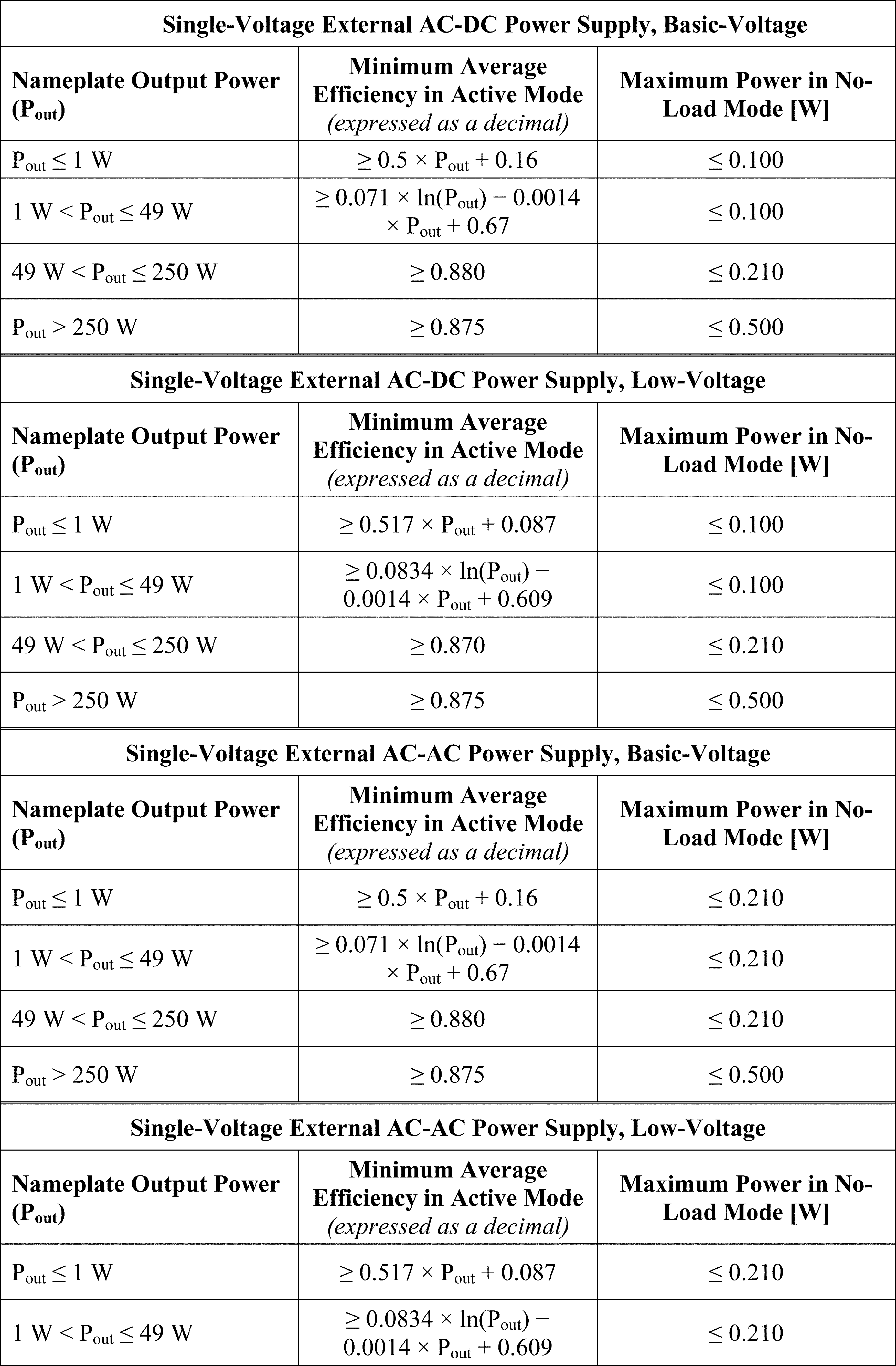

(iii) Except as provided in paragraphs (w)(5), (w)(6), and (w)(7) of this section, all external power supplies manufactured on or after February 10, 2016, shall meet the following standards:
| Class A EPS | Non-Class A EPS | |
|---|---|---|
| Direct Operation EPS | Level VI: 10 CFR 430.32(w)(1)(ii) | Level VI: 10 CFR 430.32(w)(1)(ii). |
| Indirect Operation EPS | Level IV: 10 CFR 430.32(w)(1)(i) | No Standards. |
(2) A basic model of external power supply is not subject to the energy conservation standards of paragraph (w)(1)(ii) of this section if the external power supply -
(i) Is manufactured during the period beginning on February 10, 2016, and ending on February 10, 2020;
(ii) Is marked in accordance with the External Power Supply International Efficiency Marking Protocol, as in effect on February 10, 2016;
(iii) Meets, where applicable, the standards under paragraph (w)(1)(i) of this section, and has been certified to the Secretary as meeting those standards; and
(iv) Is made available by the manufacturer only as a service part or a spare part for an end-use product that -
(A) Constitutes the primary load; and
(B) Was manufactured before February 10, 2016.
(3) The standards described in paragraph (w)(1) of this section shall not constitute an energy conservation standard for the separate end-use product to which the external power supply is connected.
(4) Any external power supply subject to the standards in paragraph (w)(1) of this section shall be clearly and permanently marked in accordance with the International Efficiency Marking Protocol for External Power Supplies (incorporated by reference; see § 430.3), published by the U.S. Department of Energy.
(5) Non-application of no-load mode requirements. The no-load mode energy efficiency standards established in paragraph (w)(1) of this section shall not apply to an external power supply that -
(i) Is an AC-to-AC external power supply;
(ii) Has a nameplate output of 20 watts or more;
(iii) Is certified to the Secretary as being designed to be connected to a security or life safety alarm or surveillance system component; and
(iv) On establishment within the External Power Supply International Efficiency Marking Protocol, as referenced in the “Energy Star Program Requirements for Single Voltage External Ac-Dc and Ac-Ac Power Supplies” (incorporated by reference, see § 430.3), published by the Environmental Protection Agency, of a distinguishing mark for products described in this clause, is permanently marked with the distinguishing mark.
(6) An external power supply shall not be subject to the standards in paragraph (w)(1) of this section if it is a device that requires Federal Food and Drug Administration (FDA) listing and approval as a medical device in accordance with section 513 of the Federal Food, Drug, and Cosmetic Act (21 U.S.C. 360(c)).
(7) A direct operation, AC-DC external power supply with nameplate output voltage less than 3 volts and nameplate output current greater than or equal to 1,000 milliamps that charges the battery of a product that is fully or primarily motor operated shall not be subject to the standards in paragraph (w)(1)(ii) of this section.
(x) General service incandescent lamps, intermediate base incandescent lamps and candelabra base incandescent lamps.
(1) The energy conservation standards in this paragraph apply to general service incandescent lamps:
(i) Intended for a general service or general illumination application (whether incandescent or not);
(ii) Has a medium screw base or any other screw base not defined in ANSI C81.61 (incorporated by reference; see § 430.3); and
(iii) Is capable of being operated at a voltage at least partially within the range of 110 to 130 volts.
(A) General service incandescent lamps manufactured after the effective dates specified in the tables below, except as described in paragraph (x)(1)(B) of this section, shall have a color rendering index greater than or equal to 80 and shall have rated wattage no greater than and rated lifetime no less than the values shown in the table below:
General Service Incandescent Lamps
| Rated lumen ranges | Maximum rate wattage | Minimum rate life-time | Effective date |
|---|---|---|---|
| 1490-2600 | 72 | 1,000 hrs | 1/1/2012 |
| 1050-1489 | 53 | 1,000 hrs | 1/1/2013 |
| 750-1049 | 43 | 1,000 hrs | 1/1/2014 |
| 310-749 | 29 | 1,000 hrs | 1/1/2014 |
(B) Modified spectrum general service incandescent lamps manufactured after the effective dates specified shall have a color rendering index greater than or equal to 75 and shall have a rated wattage no greater than and rated lifetime no less than the values shown in the table below:
Modified Spectrum General Service Incandescent Lamps
| Rated lumen ranges | Maximum rate wattage | Minimum rate life-time | Effective date |
|---|---|---|---|
| 1118-1950 | 72 | 1,000 hrs | 1/1/2012 |
| 788-1117 | 53 | 1,000 hrs | 1/1/2013 |
| 563-787 | 43 | 1,000 hrs | 1/1/2014 |
| 232-562 | 29 | 1,000 hrs | 1/1/2014 |
(2) Each candelabra base incandescent lamp shall not exceed 60 rated watts.
(3) Each intermediate base incandescent lamp shall not exceed 40 rated watts.
(y) Residential furnace fans. Residential furnace fans incorporated in the products listed in Table 1 of this paragraph and manufactured on and after July 3, 2019, shall have a fan energy rating (FER) value that meets or is less than the following values:
Table 1 - Energy Conservation Standards for Covered Residential Furnace Fans*
| Product class | FER ** (Watts/1000 cfm) |
|---|---|
| Non-Weatherized, Non-Condensing Gas Furnace Fan (NWG-NC) | FER = 0.044 × QMax + 182 |
| Non-Weatherized, Condensing Gas Furnace Fan (NWG-C) | FER = 0.044 × QMax + 195 |
| Weatherized Non-Condensing Gas Furnace Fan (WG-NC) | FER = 0.044 × QMax + 199 |
| Non-Weatherized, Non-Condensing Oil Furnace Fan (NWO-NC) | FER = 0.071 × QMax + 382 |
| Non-Weatherized Electric Furnace/Modular Blower Fan (NWEF/NWMB) | FER = 0.044 × QMax + 165 |
| Mobile Home Non-Weatherized, Non-Condensing Gas Furnace Fan (MH-NWG-NC) | FER = 0.071 × QMax + 222 |
| Mobile Home Non-Weatherized, Condensing Gas Furnace Fan (MH-NWG-C) | FER = 0.071 × QMax + 240 |
| Mobile Home Electric Furnace/Modular Blower Fan (MH-EF/MB) | FER = 0.044 × QMax + 101 |
| Mobile Home Non-Weatherized Oil Furnace Fan (MH-NWO) | Reserved |
| Mobile Home Weatherized Gas Furnace Fan (MH-WG) ** | Reserved |
(z) Battery chargers.
(1) Battery chargers manufactured on or after June 13, 2018, must have a unit energy consumption (UEC) less than or equal to the prescribed “Maximum UEC” standard when using the equations for the appropriate product class and corresponding rated battery energy as shown in the following table:
| Product class | Product class description | Rated battery energy (Ebatt **) | Special characteristic or battery voltage | Maximum UEC (kWh/yr)
(as a function of Ebatt **) |
|---|---|---|---|---|
| 1 | Low-Energy | ≤5 Wh | Inductive Connection * | 3.04 |
| 2 | Low-Energy, Low-Voltage | <100 Wh | <4 V | 0.1440 * Ebatt + 2.95 |
| 3 | Low-Energy, Medium-Voltage | 4-10 V | For Ebatt <10 Wh,
1.42 kWh/y Ebatt ≥10 Wh, 0.0255 * Ebatt + 1.16 |
|
| 4 | Low-Energy, High-Voltage | >10 V | 0.11 * Ebatt + 3.18 | |
| 5 | Medium-Energy, Low-Voltage | 100-3000 Wh | <20 V | 0.0257 * Ebatt + .815 |
| 6 | Medium-Energy, High-Voltage | ≥20 V | 0.0778 * Ebatt + 2.4 | |
| 7 | High-Energy | >3000 Wh | 0.0502 * Ebatt + 4.53 |
(2) A battery charger shall not be subject to the standards in paragraph (z)(1) of this section if it is a device that requires Federal Food and Drug Administration (FDA) listing and approval as a life-sustaining or life-supporting device in accordance with section 513 of the Federal Food, Drug, and Cosmetic Act (21 U.S.C. 360(c)).
(3) All uninterruptible power supplies (UPS) manufactured on and after January 10, 2022, that utilize a NEMA 1-15P or 5-15P input plug and have an AC output shall have an average load adjusted efficiency that meets or exceeds the values shown in the table in this paragraph (z)(3) based on the rated output power (Prated) of the UPS.
| Battery charger product class | Rated output power | Minimum efficiency |
|---|---|---|
| 10a (VFD UPSs) | 0 W < Prated ≤ 300W | −1.20E-06 * P 2rated + 7.17E-04 *Prated + 0.862. |
| 300 W < Prated ≤ 700W | −7.85E-08 * P 2rated + 1.01E-04 *Prated + 0.946. | |
| Prated > 700W | −7.23E-09 * P 2rated + 7.52E-06 *Prated + 0.977. | |
| 10b (VI UPSs) | 0 W < Prated ≤ 300W | −1.20E-06 * P 2rated + 7.19E-04 *Prated + 0.863. |
| 300 W < Prated ≤ 700W | −7.67E-08 * P 2rated + 1.05E-04 *Prated + 0.947. | |
| Prated > 700W | −4.62E-09 * P 2rated + 8.54E-06 *Prated + 0.979. | |
| 10c (VFI UPSs) | 0 W < Prated ≤ 300W | −3.13E-06 * P 2rated + 1.96E-03 *Prated + 0.543. |
| 300 W < Prated ≤ 700W | −2.60E-07 * P 2rated + 3.65E-04 *Prated + 0.764. | |
| Prated > 700W | −1.70E-08 * P 2rated + 3.85E-05 *Prated + 0.876. |
(aa) Miscellaneous refrigeration products. The energy standards as determined by the equations of the following table(s) shall be rounded off to the nearest kWh per year. If the equation calculation is halfway between the nearest two kWh per year values, the standard shall be rounded up to the higher of these values.
(1) Coolers manufactured starting on October 28, 2019 shall have Annual Energy Use (AEU) no more than:
| Product class | AEU (kWh/yr) |
|---|---|
| 1. Built-in compact | 7.88AV + 155.8 |
| 2. Built-in | |
| 3. Freestanding compact | |
| 4. Freestanding |
(2) Combination cooler refrigeration products manufactured starting on October 28, 2019 shall have Annual Energy Use (AEU) no more than:
| Product class | AEU (kWh/yr) |
|---|---|
| C-3A. Cooler with all-refrigerator - automatic defrost | 4.57AV + 130.4 |
| C-3A-BI. Built-in cooler with all-refrigerator - automatic defrost | 5.19AV + 147.8 |
| C-9. Cooler with upright freezers with automatic defrost without an automatic icemaker | 5.58AV + 147.7 |
| C-9-BI. Built-in cooler with upright freezer with automatic defrost without an automatic icemaker | 6.38AV + 168.8 |
| C-9I. Cooler with upright freezer with automatic defrost with an automatic icemaker | 5.58AV + 231.7 |
| C-9I-BI. Built-in cooler with upright freezer with automatic defrost with an automatic icemaker | 6.38AV + 252.8 |
| C-13A. Compact cooler with all-refrigerator - automatic defrost | 5.93AV + 193.7 |
| C-13A-BI. Built-in compact cooler with all-refrigerator - automatic defrost | 6.52AV + 213.1 |
(bb) Rough service lamps and vibration service lamps.
(1) Rough service lamps manufactured on or after January 25, 2018 must:
(i) Have a shatter-proof coating or equivalent technology that is compliant with NSF/ANSI 51 (incorporated by reference; see § 430.3) and is designed to contain the glass if the glass envelope of the lamp is broken and to provide effective containment over the life of the lamp;
(ii) Have a rated wattage not greater than 40 watts; and
(iii) Be sold at retail only in a package containing one lamp.
(2) Vibration service lamps manufactured on or after January 25, 2018 must:
(i) Have a rated wattage no greater than 40 watts; and
(ii) Be sold at retail only in a package containing one lamp.
(cc) Portable air conditioners. Single-duct portable air conditioners and dual-duct portable air conditioners manufactured on or after January 10, 2025 must have a combined energy efficiency ratio (CEER) in Btu/Wh no less than SACC: Seasonally adjusted cooling capacity in Btu/h, as determined in appendix CC of subpart B of this part.
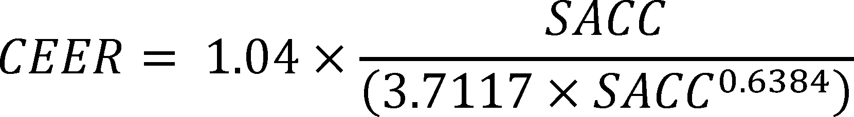
[54 FR 6077, Feb. 7, 1989]
§ 430.33 Preemption of State regulations.
(a) Any State regulation providing for any energy conservation standard, or water conservation standard (in the case of faucets, showerheads, water closets, and urinals), or other requirement with respect to the energy efficiency, energy use, or water use (in the case of faucets, showerheads, water closets, or urinals) of a covered product that is not identical to a Federal standard in effect under this subpart is preempted by that standard, except as provided for in sections 325(i)(6)(A)(vi), 327(b) and (c) of the Act.
(b) No State regulation, or revision thereof, concerning the energy efficiency, energy use, or water use of the covered product shall be effective with respect to such covered product, unless the State regulation or revision in the case of any portion of any regulation that establishes requirements for general service incandescent lamps, intermediate base incandescent lamps, or candelabra base lamps, was enacted or adopted by the State of California or Nevada before December 4, 2007, except that—
(1) The regulation adopted by the California Energy Commission with an effective date of January 1, 2008, shall only be effective until the effective date of the Federal standard for the applicable lamp category under paragraphs (A), (B), and (C) of section 325(i)(1) of EPCA; and
(2) The States of California and Nevada may, at any time, modify or adopt a State standard for general service lamps to conform with Federal standards with effective dates no earlier than 12 months prior to the Federal effective dates prescribed under paragraphs (A), (B), and (C) of section 325(i)(1) of EPCA, at which time any prior regulations adopted by the State of California or Nevada shall no longer be effective.
[63 FR 13318, Mar. 18, 1998, as amended at 74 FR 12070, Mar. 23, 2009; 78 FR 62993, Oct. 23, 2013]
§ 430.34 Energy and water conservation standards amendments
The Department of Energy may not prescribe any amended standard which increases the maximum allowable energy use or, in the case of showerheads, faucets, water closets or urinals, the maximum allowable water use, or which decreases the minimum required energy efficiency of a covered product.
[67 FR 36406, May 23, 2002]
§ 430.35 Petitions with respect to general service lamps.
(a) Any person may petition the Secretary for an exemption for a type of general service lamp from the requirements of this subpart. The Secretary may grant an exemption only to the extent that the Secretary finds, after a hearing and opportunity for public comment, that it is not technically feasible to serve a specialized lighting application (such as a military, medical, public safety or certified historic lighting application) using a lamp that meets the requirements of this subpart. To grant an exemption for a product under this paragraph, the Secretary shall include, as an additional criterion, that the exempted product is unlikely to be used in a general service lighting application.
(b) Any person may petition the Secretary to establish standards for lamp shapes or bases that are excluded from the definition of general service lamps. The petition shall include evidence that the availability or sales of exempted lamps have increased significantly since December 19, 2007. The Secretary shall grant a petition if the Secretary finds that:
(1) The petition presents evidence that demonstrates that commercial availability or sales of exempted incandescent lamp types have increased significantly since December 19, 2007 and are being widely used in general lighting applications; and
(2) Significant energy savings could be achieved by covering exempted products, as determined by the Secretary based on sales data provided to the Secretary from manufacturers and importers.
[74 FR 12070, Mar. 23, 2009]
Appendix A to Subpart C of Part 430 - Procedures, Interpretations, and Policies for Consideration of New or Revised Energy Conservation Standards and Test Procedures for Consumer Products and Certain Commercial/Industrial Equipment
1. Objectives
2. Scope
3. Mandatory Application of the Process Rule
4. Setting Priorities for Rulemaking Activity
5. Coverage Determination Rulemakings
6. Process for Developing Energy Conservation Standards
7. Policies on Selection of Standards
8. Test Procedures
9. ASHRAE Equipment
10. Direct Final Rules
11. Negotiated Rulemaking Process
12. Principles for Distinguishing Between Effective and Compliance Dates
13. Principles for the Conduct of the Engineering Analysis
14. Principles for the Analysis of Impacts on Manufacturers
15. Principles for the Analysis of Impacts on Consumers
16. Consideration of Non-Regulatory Approaches
17. Cross-cutting Analytical Assumptions
1. Objectives
This appendix establishes procedures, interpretations, and policies that DOE will follow in the consideration and promulgation of new or revised appliance energy conservation standards and test procedures under the Energy Policy and Conservation Act (EPCA). This appendix applies to both covered consumer products and covered commercial/industrial equipment. The Department's objectives in establishing these procedures include:
(a) Provide for early input from stakeholders. The Department seeks to provide opportunities for public input early in the rulemaking process so that the initiation and direction of rulemakings is informed by comment from interested parties. Under the procedures established by this appendix, DOE will seek early input from interested parties in determining whether establishing new or amending existing energy conservation standards will result in significant savings of energy and is economically justified and technologically feasible. In the context of test procedure rulemakings, DOE will seek early input from interested parties in determining whether -
(1) Establishing a new or amending an existing test procedure will better measure the energy efficiency, energy use, water use (as specified in EPCA), or estimated annual operating cost of a covered product/equipment during a representative average use cycle or period of use (for consumer products); and
(2) Will not be unduly burdensome to conduct.
(b) Increase predictability of the rulemaking timetable. The Department seeks to make informed, strategic decisions about how to deploy its resources on the range of possible standards and test procedure development activities, and to announce these prioritization decisions so that all interested parties have a common expectation about the timing of different rulemaking activities. Further, DOE will offer the opportunity to provide input on the prioritization of rulemakings through a request for comment as DOE begins preparation of its Regulatory Agenda each spring.
(c) Eliminate problematic design options early in the process. The Department seeks to eliminate from consideration, early in the process, any design options that present unacceptable problems with respect to manufacturability, consumer utility, or safety, so that the detailed analysis can focus only on viable design options. Under the procedures in this appendix, DOE will eliminate from consideration design options if it concludes that manufacture, installation or service of the design will be impractical, or that the design option will have a material adverse impact on the utility of the product, or if the design option will have a material adverse impact on safety or health. DOE will also eliminate from consideration proprietary design options that represent a unique pathway to achieving a given efficiency level. This screening will be done at the outset of a rulemaking.
(d) Fully consider non-regulatory approaches. The Department seeks to understand the effects of market forces and voluntary programs on encouraging the purchase of energy efficient products so that the incremental impacts of a new or revised standard can be accurately assessed and the Department can make informed decisions about where standards and voluntary programs can be used most effectively. DOE will continue to support voluntary efforts by manufacturers, retailers, utilities, and others to increase product/equipment efficiency.
(e) Conduct thorough analysis of impacts. In addition to understanding the aggregate social and private costs and benefits of standards, the Department seeks to understand the distribution of those costs and benefits among consumers, manufacturers, and others, as well as the uncertainty associated with these analyses of costs and benefits, so that any adverse impacts on subgroups and uncertainty concerning any adverse impacts can be fully considered in selecting a standard. Pursuant to this appendix, the analyses will consider the variability of impacts on significant groups of manufacturers and consumers in addition to aggregate social and private costs and benefits, report the range of uncertainty associated with these impacts, and take into account cumulative impacts of regulation on manufacturers. The Department will also conduct appropriate analyses to assess the impact that new or amended test procedures will have on manufacturers and consumers.
(f) Use transparent and robust analytical methods. The Department seeks to use qualitative and quantitative analytical methods that are fully documented for the public and that produce results that can be explained and reproduced, so that the analytical underpinnings for policy decisions on standards are as sound and well-accepted as possible.
(g) Support efforts to build consensus on standards. The Department seeks to encourage development of consensus proposals for new or revised standards because standards with such broad-based support are likely to balance effectively the various interests affected by such standards.
2. Scope
The procedures, interpretations, and policies described in this appendix apply to rulemakings concerning new or revised Federal energy conservation standards and test procedures, and related rule documents (i.e., coverage determinations) for consumer products in Part A and commercial and industrial equipment under Part A-1 of the Energy Policy and Conservation Act (EPCA), as amended, except covered ASHRAE equipment in Part A-1 are governed separately under section 9 in this appendix.
3. Mandatory Application of the Process Rule
The rulemaking procedures established in this appendix are binding on DOE.
4. Setting Priorities for Rulemaking Activity
(a) In establishing its priorities for undertaking energy conservation standards and test procedure rulemakings, DOE will consider the following factors, consistent with applicable legal obligations:
(1) Potential energy savings;
(2) Potential social and private, including environmental or energy security, benefits;
(3) Applicable deadlines for rulemakings;
(4) Incremental DOE resources required to complete the rulemaking process;
(5) Other relevant regulatory actions affecting the products/equipment;
(6) Stakeholder recommendations;
(7) Evidence of energy efficiency gains in the market absent new or revised standards;
(8) Status of required changes to test procedures; and
(9) Other relevant factors.
(b) DOE will offer the opportunity to provide input on prioritization of rulemakings through a request for comment as DOE begins preparation of its Regulatory Agenda each spring.
5. Coverage Determination Rulemakings
(a) DOE has discretion to conduct proceedings to determine whether additional consumer products and commercial/industrial equipment should be covered under EPCA if certain statutory criteria are met. (42 U.S.C. 6292 and 42 U.S.C. 6295(l) for consumer products; 42 U.S.C. 6312 for commercial/industrial equipment)
(b) If DOE determines to initiate the coverage determination process, it will first publish a notice of proposed determination, providing an opportunity for public comment of not less than 60 days, in which DOE will explain how such products/equipment that it seeks to designate as “covered” meet the statutory criteria for coverage and why such coverage is “necessary or appropriate” to carry out the purposes of EPCA. In the case of commercial equipment, DOE will follow the same process, except that the Department must demonstrate that coverage of the equipment type is “necessary” to carry out the purposes of EPCA.
(c) DOE will publish its final decision on coverage as a separate notice, an action that will be completed prior to the initiation of any test procedure or energy conservation standards rulemaking (i.e., DOE will not issue any Requests for Information (RFIs), Notices of Data Availability (NODAs), or any other mechanism to gather information for the purpose of initiating a rulemaking to establish a test procedure or energy conservation standard for the proposed covered product/equipment prior to finalization of the coverage determination). If DOE determines that coverage is warranted, DOE will proceed with its typical rulemaking process for both test procedures and standards. Specifically, DOE will finalize coverage for a product/equipment at least 180 days prior to publication of a proposed rule to establish a test procedure. And, DOE will complete the test procedure rulemaking at least 180 days prior to publication of a proposed energy conservation standard.
(d) If, during the substantive rulemaking proceedings to establish test procedures or energy conservation standards after completing a coverage determination, DOE finds it necessary and appropriate to expand or reduce the scope of coverage, a new coverage determination process will be initiated and finalized prior to moving forward with the test procedure or standards rulemaking.
6. Process for Developing Energy Conservation Standards
This section describes the process to be used in developing energy conservation standards for covered products and equipment other than those covered equipment subject to ASHRAE/IES Standard 90.1.
(a) Early Assessment.
(1) As the first step in any proceeding to consider establishing or amending any energy conservation standard, DOE will publish a document in the Federal Register announcing that DOE is considering initiating a rulemaking proceeding. As part of that document, DOE will solicit submission of related comments, including data and information on whether DOE should proceed with the rulemaking, including whether any new or amended rule would be cost effective, economically justified, technologically feasible, or would result in a significant savings of energy. Based on the information received in response to the notice and its own analysis, DOE will determine whether to proceed with a rulemaking for a new or amended energy conservation standard or an amended test procedure. If DOE determines that a new or amended standard would not satisfy applicable statutory criteria, DOE would engage in notice and comment rulemaking to issue a determination that a new or amended standard is not warranted. If DOE receives sufficient information suggesting it could justify a new or amended standard or the information received is inconclusive with regard to the statutory criteria, DOE would undertake the preliminary stages of a rulemaking to issue or amend an energy conservation standard, as discussed further in paragraph (a)(2) of this section.
(2) If the Department determines it is appropriate to proceed with a rulemaking, the preliminary stages of a rulemaking to issue or amend an energy conservation standard that DOE will undertake will be a Framework Document and Preliminary Analysis, or an Advance Notice of Proposed Rulemaking (ANOPR). Requests for Information (RFI) and Notices of Data Availability (NODA) could be issued, as appropriate, in addition to these preliminary-stage documents.
(3) In those instances where the early assessment either suggested that a new or amended energy conservation standard might be justified or in which the information was inconclusive on this point, and DOE undertakes the preliminary stages of a rulemaking to establish or amend an energy conservation standard, DOE may still ultimately determine that such a standard is not economically justified, technologically feasible or would not result in a significant savings of energy. Therefore, DOE will examine the potential costs and benefits and energy savings potential of a new or amended energy conservation standard at the preliminary stage of the rulemaking. DOE notes that it will, consistent with its statutory obligations, consider both cost effectiveness and economic justification when issuing a determination not to amend a standard.
(b) Significant Savings of Energy.
(1) In evaluating the prospects of proposing a new or amended standard - or in determining that no new or amended standard is needed - DOE will first look to the projected energy savings that are likely to result. DOE will determine as a preliminary matter whether the rulemaking has the potential to result in “significant energy savings.” If the rulemaking passes the significant energy savings threshold, DOE will then compare these projected savings against the technological feasibility of and likely costs necessary to meet the new or amended standards needed to achieve these energy savings.
(2) Under its significant energy savings analysis, DOE will examine both the total amount of projected energy savings and the relative percentage decrease in energy usage that could be obtained from establishing or amending energy conservation standards for a given covered product or equipment. This examination will be based on the applicable product or equipment type as appropriate and will not be used to selectively examine classes or sub-classes of products and equipment solely for the purposes of projecting whether potential energy savings would satisfy (or not satisfy) the applicable thresholds detailed in this rule. Under the first step of this approach, the projected energy savings from a potential maximum technologically feasible (“max-tech”) standard will be evaluated against a threshold of 0.3 quads of site energy saved over a 30-year period.
(3) If the projected max-tech energy savings does not meet or exceed this threshold, those max-tech savings would then be compared to the total energy usage of the covered product or equipment to calculate a potential percentage reduction in energy usage.
(4) If this comparison does not yield a reduction in site energy use of at least 10 percent over a 30-year period, the analysis will end, and DOE will propose to determine that no significant energy savings would likely result from setting new or amended standards.
(5) If either one of the thresholds described in paragraphs (b)(3) or (b)(4) of this section is reached, DOE will conduct analyses to ascertain whether a standard can be prescribed that produces the maximum improvement in energy efficiency that is both technologically feasible and economically justified and still constitutes significant energy savings (using the same criteria of either 0.3 quad of aggregate site energy savings or a 10-percent decrease in energy use, as measured in quads - both over a 30-year period) at the level determined to be economically justified.
(6) In the case of ASHRAE equipment, DOE will examine the potential energy savings involved across the equipment category at issue.
(c) Design options -
(1) General. Once the Department has initiated a rulemaking for a specific product/equipment but before publishing a proposed rule to establish or amend standards, DOE will identify the product/equipment categories and design options to be analyzed in detail, as well as those design options to be eliminated from further consideration. During the pre-proposal stages of the rulemaking, interested parties may be consulted to provide information on key issues through a variety of rulemaking documents. The preliminary stages of a rulemaking to issue or amend an energy conservation standard that DOE will undertake will be a framework document and preliminary analysis, or an advance notice of proposed rulemaking (ANOPR). Requests for Information (RFI) and Notice of Data Availability (NODA) could also be issued, as appropriate.
(2) Identification and screening of design options. During the pre-NOPR phase of the rulemaking process, the Department will develop a list of design options for consideration. Initially, the candidate design options will encompass all those technologies considered to be technologically feasible. Following the development of this initial list of design options, DOE will review each design option based on the factors described in paragraph (c)(3) of this section and the policies stated in section 7 of this Appendix (i.e. Policies on Selection of Standards). The reasons for eliminating or retaining any design option at this stage of the process will be fully documented and published as part of the NOPR and as appropriate for a given rule, in the pre-NOPR documents. The technologically feasible design options that are not eliminated in this screening will be considered further in the Engineering Analysis described in paragraph (d) of this section.
(3) Factors for screening of design options. The factors for screening design options include:
(i) Technological feasibility. Technologies incorporated in commercial products or in working prototypes will be considered technologically feasible.
(ii) Practicability to manufacture, install and service. If mass production of a technology under consideration for use in commercially-available products (or equipment) and reliable installation and servicing of the technology could be achieved on the scale necessary to serve the relevant market at the time of the effective date of the standard, then that technology will be considered practicable to manufacture, install and service.
(iii) Adverse Impacts on Product Utility or Product Availability.
(iv) Adverse Impacts on Health or Safety.
(v) Unique-Pathway Proprietary Technologies. If a design option utilizes proprietary technology that represents a unique pathway to achieving a given efficiency level, that technology will not be considered further.
(d) Engineering analysis of design options and selection of candidate standard levels. After design options are identified and screened, DOE will perform the engineering analysis and the benefit/cost analysis and select the candidate standard levels based on these analyses. The results of the analyses will be published in a Technical Support Document (TSD) to accompany the appropriate rulemaking documents.
(1) Identification of engineering analytical methods and tools. DOE will select the specific engineering analysis tools (or multiple tools, if necessary to address uncertainty) to be used in the analysis of the design options identified as a result of the screening analysis.
(2) Engineering and life-cycle cost analysis of design options. DOE and its contractor will perform engineering and life-cycle cost analyses of the design options.
(3) Review by stakeholders. Interested parties will have the opportunity to review the results of the engineering and life-cycle cost analyses. If appropriate, a public workshop will be conducted to review these results. The analyses will be revised as appropriate on the basis of this input.
(4) New information relating to the factors used for screening design options. If further information or analysis leads to a determination that a design option, or a combination of design options, has unacceptable impacts, that design option or combination of design options will not be included in a candidate standard level.
(5) Selection of candidate standard levels. Based on the results of the engineering and life-cycle cost analysis of design options and the policies stated in paragraph (c) of this section, DOE will select the candidate standard levels for further analysis.
(e) Pre-NOPR Stage -
(1) Documentation of decisions on candidate standard selection.
(i) If the early assessment and screening analysis indicates that continued development of a standard is appropriate, the Department will publish either:
(A) A notice accompanying a framework document and, subsequently, a preliminary analysis or;
(B) An ANOPR. The notice document will be published in the Federal Register, with accompanying documents referenced and posted in the appropriate docket.
(ii) If DOE determines at any point in the pre-NOPR stage that no candidate standard level is likely to produce the maximum improvement in energy efficiency that is both technologically feasible and economically justified or constitute significant energy savings, that conclusion will be announced in the Federal Register with an opportunity for public comment provided to stakeholders. In such cases, the Department will proceed with a rulemaking that proposes not to adopt new or amended standards.
(2) Public comment and hearing. The length of the public comment period for pre-NOPR rulemaking documents will vary depending upon the circumstances of the particular rulemaking, but will not be less than 75 calendar days. For such documents, DOE will determine whether a public hearing is appropriate.
(3) Revisions based on comments. Based on consideration of the comments received, any necessary changes to the engineering analysis or the candidate standard levels will be made.
(f) Analysis of impacts and selection of proposed standard level. After the pre-NOPR stage, if DOE has determined preliminarily that a candidate standard level is likely to produce the maximum improvement in energy efficiency that is both technologically feasible and economically justified or constitute significant energy savings, economic analyses of the impacts of the candidate standard levels will be conducted. The Department will propose new or amended standards based on the results of the impact analysis.
(1) Identification of issues for analysis. The Department, in consideration of comments received, will identify issues that will be examined in the impacts analysis.
(2) Identification of analytical methods and tools. DOE will select the specific economic analysis tools (or multiple tools if necessary to address uncertainty) to be used in the analysis of the candidate standard levels.
(3) Analysis of impacts. DOE will conduct the analysis of the impacts of candidate standard levels.
(4) Factors to be considered in selecting a proposed standard. The factors to be considered in selection of a proposed standard include:
(i) Impacts on manufacturers. The analysis of private manufacturer impacts will include: Estimated impacts on cash flow; assessment of impacts on manufacturers of specific categories of products/equipment and small manufacturers; assessment of impacts on manufacturers of multiple product-specific Federal regulatory requirements, including efficiency standards for other products and regulations of other agencies; and impacts on manufacturing capacity, plant closures, and loss of capital investment.
(ii) Private Impacts on consumers. The analysis of consumer impacts will include: Estimated private energy savings impacts on consumers based on national average energy prices and energy usage; assessments of impacts on subgroups of consumers based on major regional differences in usage or energy prices and significant variations in installation costs or performance; sensitivity analyses using high and low discount rates reflecting both private transactions and social discount rates and high and low energy price forecasts; consideration of changes to product utility, changes to purchase rate of products, and other impacts of likely concern to all or some consumers, based to the extent practicable on direct input from consumers; estimated life-cycle cost with sensitivity analysis; consideration of the increased first cost to consumers and the time required for energy cost savings to pay back these first costs; and loss of utility.
(iii) Impacts on competition, including industry concentration analysis.
(iv) Impacts on utilities. The analysis of utility impacts will include estimated marginal impacts on electric and gas utility costs and revenues.
(v) National energy, economic, and employment impacts. The analysis of national energy, economic, and employment impacts will include: Estimated energy savings by fuel type; estimated net present value of benefits to all consumers; and estimates of the direct and indirect impacts on employment by appliance manufacturers, relevant service industries, energy suppliers, suppliers of complementary and substitution products, and the economy in general.
(vi) Impacts on the environment. The analysis of environmental impacts will include estimated impacts on emissions of carbon and relevant criteria pollutants, and impacts on pollution control costs.
(vii) Impacts of non-regulatory approaches. The analysis of energy savings and consumer impacts will incorporate an assessment of the impacts of market forces and existing voluntary programs in promoting product/equipment efficiency, usage, and related characteristics in the absence of updated efficiency standards.
(viii) New information relating to the factors used for screening design options.
(g) Notice of Proposed Rulemaking -
(1) Documentation of decisions on proposed standard selection. The Department will publish a NOPR in the Federal Register that proposes standard levels and explains the basis for the selection of those proposed levels, and will post on its website a draft TSD documenting the analysis of impacts. The draft TSD will also be posted in the appropriate docket on http://www.regulations.gov. As required by 42 U.S.C. 6295(p)(1) of EPCA, the NOPR also will describe the maximum improvement in energy efficiency or maximum reduction in energy use that is technologically feasible and, if the proposed standards would not achieve these levels, the reasons for proposing different standards.
(2) Public comment and hearing. There will be not less than 75 days for public comment on the NOPR, with at least one public hearing or workshop. (42 U.S.C. 6295(p)(2) and 42 U.S.C. 6306).
(3) Revisions to impact analyses and selection of final standard. Based on the public comments received, DOE will review the proposed standard and impact analyses, and make modifications as necessary. If major changes to the analyses are required at this stage, DOE will publish a Supplemental Notice of Proposed Rulemaking (SNOPR), when required. DOE may also publish a NODA or RFI, where appropriate.
(h) Final Rule. The Department will publish a Final Rule in the Federal Register that promulgates standard levels, responds to public comments received on the NOPR, and explains how the selection of those standards meets the statutory requirement that any new or amended energy conservation standard produces the maximum improvement in energy efficiency that is both technologically feasible and economically justified and constitutes significant energy savings, accompanied by a final TSD.
7. Policies on Selection of Standards
(a) Purpose.
(1) Section 5 describes the process that will be used to consider new or revised energy efficiency standards and lists a number of factors and analyses that will be considered at specified points in the process. Department policies concerning the selection of new or revised standards, and decisions preliminary thereto, are described in this section. These policies are intended to elaborate on the statutory criteria provided in 42 U.S.C. 6295 of EPCA.
(2) The procedures described in this section are intended to assist the Department in making the determinations required by EPCA and do not preclude DOE's consideration of any other information consistent with the relevant statutory criteria. The Department will consider pertinent information in determining whether a new or revised standard is consistent with the statutory criteria.
(b) Screening design options. These factors will be considered as follows in determining whether a design option will receive any further consideration:
(1) Technological feasibility. Technologies that are not incorporated in commercial products or in commercially-viable, existing prototypes will not be considered further.
(2) Practicability to manufacture, install and service. If it is determined that mass production of a technology in commercial products and reliable installation and servicing of the technology could not be achieved on the scale necessary to serve the relevant market at the time of the compliance date of the standard, then that technology will not be considered further.
(3) Impacts on product utility. If a technology is determined to have significant adverse impact on the utility of the product/equipment to subgroups of consumers, or result in the unavailability of any covered product type with performance characteristics (including reliability), features, sizes, capacities, and volumes that are substantially the same as products generally available in the U.S. at the time, it will not be considered further.
(4) Safety of technologies. If it is determined that a technology will have significant adverse impacts on health or safety, it will not be considered further.
(5) Unique-pathway proprietary technologies. If a technology has proprietary protection and represents a unique pathway to achieving a given efficiency level, it will not be considered further, due to the potential for monopolistic concerns.
(c) Identification of candidate standard levels. Based on the results of the engineering and cost/benefit analyses of design options, DOE will identify the candidate standard levels for further analysis. Candidate standard levels will be selected as follows:
(1) Costs and savings of design options. Design options that have payback periods that exceed the median life of the product or which result in life-cycle cost increases relative to the base case, using typical fuel costs, usage, and private discount rates, will not be used as the basis for candidate standard levels.
(2) Further information on factors used for screening design options. If further information or analysis leads to a determination that a design option, or a combination of design options, has unacceptable impacts under the policies stated in this Appendix, that design option or combination of design options will not be included in a candidate standard level.
(3) Selection of candidate standard levels. Candidate standard levels, which will be identified in the pre-NOPR documents and on which impact analyses will be conducted, will be based on the remaining design options.
(i) The range of candidate standard levels will typically include:
(A) The most energy-efficient combination of design options;
(B) The combination of design options with the lowest life-cycle cost; and
(C) A combination of design options with a payback period of not more than three years.
(ii) Candidate standard levels that incorporate noteworthy technologies or fill in large gaps between efficiency levels of other candidate standard levels also may be selected.
(d) Pre-NOPR Stage. New information provided in public comments on any pre-NOPR documents will be considered to determine whether any changes to the candidate standard levels are needed before proceeding to the analysis of impacts.
(e)
(1) Selection of proposed standard. Based on the results of the analysis of impacts, DOE will select a standard level to be proposed for public comment in the NOPR. As required under 42 U.S.C. 6295(o)(2)(A), any new or revised standard must be designed to achieve the maximum improvement in energy efficiency that is determined to be both technologically feasible and economically justified.
(2) Statutory policies. The fundamental policies concerning the selection of standards include:
(i) A trial standard level will not be proposed or promulgated if the Department determines that it is not both technologically feasible and economically justified. (42 U.S.C. 6295(o)(2)(A) and 42 U.S.C. (o)(3)(B)) For a trial standard level to be economically justified, the Secretary must determine that the benefits of the standard exceed its burdens by, to the greatest extent practicable, considering the factors listed in 42 U.S.C. 6295(o)(2)(B)(i). In making such a determination, the Secretary shall compare the benefits and burdens of the standard against the benefits and burdens of the baseline case (“no new standards” case) and all other trial standard levels under consideration. This comparative analysis includes assessing the incremental changes in costs and benefits for each TSL's benefits and burdens relative to other TSLs and as part of a holistic analysis across all TSLs. 42 U.S.C. 6295(o)(2)(B). The Secretary will also consider, consistent with the statute, other economic measures such as life-cycle cost analysis, manufacturer impact analysis, and other relevant measures. A standard level is subject to a rebuttable presumption that it is economically justified if the payback period is three years or less. (42 U.S.C. 6295(o)(2)(B)(iii))
(ii) If the Department determines that interested persons have established by a preponderance of the evidence that a standard level is likely to result in the unavailability in the United States of any covered product/equipment type (or class) with performance characteristics (including reliability), features, sizes, capacities, and volumes that are substantially the same as products generally available in the U.S. at the time of the determination, then that standard level will not be proposed. (42 U.S.C. 6295(o)(4))
(iii) If the Department determines that a standard level would not result in significant conservation of energy, that standard level will not be proposed. (42 U.S.C. 6295(o)(3)(B))
(f) Selection of a final standard. New information provided in the public comments on the NOPR and any analysis by the Department of Justice concerning impacts on competition of the proposed standard will be considered to determine whether issuance of a new or amended energy conservation standard produces the maximum improvement in energy efficiency that is both technologically feasible and economically justified and still constitutes significant energy savings or whether any change to the proposed standard level is needed before proceeding to the final rule. The same policies used to select the proposed standard level, as described in this section, will be used to guide the selection of the final standard level or a determination that no new or amended standard is justified.
8. Test Procedures
(a) General. As with the early assessment process for energy conservation standards, DOE believes that early stakeholder input is also very important during test procedure rulemakings. DOE will follow an early assessment process similar to that described in the preceding sections discussing DOE's consideration of amended energy conservation standards. Consequently, DOE will publish a notice in the Federal Register whenever DOE is considering initiation of a rulemaking to amend a test procedure. In that notice, DOE will request submission of comments, including data and information on whether an amended test procedure rule would:
(1) More accurately measure energy efficiency, energy use, water use (as specified in EPCA), or estimated annual operating cost of a covered product during a representative average use cycle or period of use without being unduly burdensome to conduct; or
(2) Reduce testing burden. DOE will review comments submitted and, subject to statutory obligations, determine whether it agrees with the submitted information. If DOE determines that an amended test procedure is not justified at that time, it will not pursue the rulemaking and will publish a notice in the Federal Register to that effect. If DOE receives sufficient information suggesting an amended test procedure could more accurately measure energy efficiency, energy use, water use (as specified in EPCA), or estimated annual operating cost of a covered product during a representative average use cycle or period of use and not be unduly burdensome to conduct, reduce testing burden, or the information received is inconclusive with regard to these points, DOE would undertake the preliminary stages of a rulemaking to amend the test procedure, as discussed further in the paragraphs that follow in this section.
(b) Identifying the need to modify test procedures. DOE will identify any necessary modifications to established test procedures prior to initiating the standards development process. It will consider all stakeholder comments with respect to needed test procedure modifications. If DOE determines that it is appropriate to continue the test procedure rulemaking after the early assessment process, it would provide further opportunities for early public input through Federal Register documents, including NODAs and/or RFIs.
(c) Adoption of Industry Test Methods. DOE will adopt industry test standards as DOE test procedures for covered products and equipment, unless such methodology would be unduly burdensome to conduct or would not produce test results that reflect the energy efficiency, energy use, water use (as specified in EPCA) or estimated operating costs of that equipment during a representative average use cycle.
(d) Issuing final test procedure modification. Test procedure rulemakings establishing methodologies used to evaluate proposed energy conservation standards will be finalized at least 180 days prior to publication of a NOPR proposing new or amended energy conservation standards.
(e) Effective Date of Test Procedures. If required only for the evaluation and issuance of updated efficiency standards, use of the modified test procedures typically will not be required until the implementation date of updated standards.
9. ASHRAE Equipment
(a) EPCA provides that ASHRAE equipment are subject to unique statutory requirements and their own set of timelines. More specifically, pursuant to EPCA's statutory scheme for covered ASHRAE equipment, DOE is required to consider amending the existing Federal energy conservation standards and test procedures for certain enumerated types of commercial and industrial equipment (generally, commercial water heaters, commercial packaged boilers, commercial air-conditioning and heating equipment, and packaged terminal air conditioners and heat pumps) when ASHRAE Standard 90.1 is amended with respect to standards and test procedures applicable to such equipment. Not later than 180 days after the amendment of the standard, the Secretary will publish in the Federal Register for public comment an analysis of the energy savings potential of amended energy efficiency standards. For each type of equipment, EPCA directs that if ASHRAE Standard 90.1 is amended, not later than 18 months after the date of publication of the amendment to ASHRAE Standard 90.1, DOE must adopt amended energy conservation standards at the new efficiency level in ASHRAE Standard 90.1 as the uniform national standard for such equipment, or amend the test procedure referenced in ASHRAE Standard 90.1 for the equipment at issue to be consistent with the applicable industry test procedure, respectively, unless -
(1) DOE determines by rule, and supported by clear and convincing evidence, that a more-stringent standard would result in significant additional conservation of energy and is technologically feasible and economically justified; or
(2) The test procedure would not meet the requirements for such test procedures specified in EPCA. In such case, DOE must adopt the more stringent standard not later than 30 months after the date of publication of the amendment to ASHRAE/IES Standard 90.1 for the affected equipment.
(b) For ASHRAE equipment, DOE will adopt the revised ASHRAE levels or the industry test procedure, as contemplated by EPCA, except in very limited circumstances.
With respect to DOE's consideration of standards more-stringent than the ASHRAE levels or changes to the industry test procedure, DOE will do so only if it can meet a very high bar to demonstrate the “clear and convincing evidence” threshold. Clear and convincing evidence would exist only where the specific facts and data made available to DOE regarding a particular ASHRAE amendment demonstrates that there is no substantial doubt that a standard more stringent than that contained in the ASHRAE Standard 90.1 amendment is permitted because it would result in a significant additional amount of energy savings, is technologically feasible and economically justified, or, in the case of test procedures, that the industry test procedure does not meet the EPCA requirements. DOE will make this determination only after seeking data and information from interested parties and the public to help inform the Agency's views. DOE will seek from interested stakeholders and the public data and information to assist in making this determination, prior to publishing a proposed rule to adopt more-stringent standards or a different test procedure.
(c) DOE's review in adopting amendments based on an action by ASHRAE to amend Standard 90.1 is strictly limited to the specific standards or test procedure amendment for the specific equipment for which ASHRAE has made a change (i.e., determined down to the equipment class level). DOE believes that ASHRAE not acting to amend Standard 90.1 is tantamount to a decision that the existing standard remain in place. Thus, when undertaking a review as required by 42 U.S.C. 6313(a)(6)(C), DOE would need to find clear and convincing evidence, as defined in this section, to issue a standard more stringent than the existing standard for the equipment at issue.
10. Direct Final Rules
(a) A direct final rule (DFR), as contemplated in 42 U.S.C. 6295(p)(4), is a procedural mechanism separate from the negotiated rulemaking process outlined under the Negotiated Rulemaking Act (5 U.S.C. 563). DOE may issue a DFR adopting energy conservation standards for a covered product provided that:
(1) DOE receives a joint proposal from a group of “interested persons that are fairly representative of relevant points of view,” which does not include DOE as a member of the group. At a minimum, to be “fairly representative of relevant points of view” the group submitting a joint statement must include larger concerns and small businesses in the regulated industry/manufacturer community, energy advocates, energy utilities, as appropriate, consumers, and States. However, it will be necessary to evaluate the meaning of “fairly representative” on a case-by-case basis, subject to the circumstances of a particular rulemaking, to determine whether additional parties must be part of a joint statement in order to be “fairly representative of relevant points of view.”
(2) This paragraph (a)(2) describes the steps DOE will follow with respect to a DFR.
(i) DOE must determine whether the energy conservation standard recommended in the joint proposal is in accordance with the requirements of 42 U.S.C. 6295(o) or section 342(a)(6)(B) as applicable. Because the DFR provision is procedural, and not a separate grant of rulemaking authority, any standard issued under the DFR process must comply fully with the provisions of the EPCA subsection under which the rule is authorized. DOE will not accept or issue as a DFR a submitted joint proposal that does not comply with all applicable EPCA requirements.
(ii) Upon receipt of a joint statement recommending energy conservation standards, DOE will publish in the Federal Register that statement, as submitted to DOE, in order to obtain feedback as to whether the joint statement was submitted by a group that is fairly representative of relevant points of view. If DOE determines that the DFR was not submitted by a group that is fairly representative of relevant points of view, DOE will not move forward with a DFR and will consider whether any further rulemaking activity is appropriate. If the Secretary determines that a DFR cannot be issued based on the statement, the Secretary shall publish a notice of the determination, together with an explanation of the reasons for the determination.
(iii) Simultaneous with the issuance of a DFR, DOE must also publish a NOPR containing the same energy conservation standards as in the DFR. Following publication of the DFR, DOE must solicit public comment for a period of at least 110 days; then, not later than 120 days after issuance of the DFR, the Secretary must determine whether any adverse comments “may provide a reasonable basis for withdrawing the direct final rule,” based on the rulemaking record. If DOE determines that one or more substantive comments objecting to the DFR provides a sufficient reason to withdraw the DFR, DOE will do so, and will instead proceed with the published NOPR (unless the information provided suggests that withdrawal of that NOPR would likewise be appropriate). In making this determination, DOE may consider comments as adverse, even if the issue was brought up previously during DOE-initiated discussions (e.g. publication of a framework or RFI document), if the Department concludes that the comments merit further consideration.
11. Negotiated Rulemaking Process
(a)
(1) In those instances where negotiated rulemaking is determined to be appropriate, DOE will comply with the requirements of the Negotiated Rulemaking Act (NRA) (5 U.S.C. 561-570) and the requirements of the Federal Advisory Committee Act (FACA) (5 U.S.C. App. 2). To facilitate potential negotiated rulemakings, and to comply with the requirements of the NRA and the FACA, DOE established the Appliance Standards and Rulemaking Federal Advisory Committee (ASRAC). Working groups can be established as subcommittees of ASRAC, from time to time, and for specific products/equipment, with one member representative from the ASRAC committee attending and participating in the meetings of a specific working group. (Consistent with 5 U.S.C. 565(b), committee membership is limited to 25 members, unless the agency determines that more members are necessary for the functioning of the committee or to achieve balanced membership.) Ultimately, the working group reports to ASRAC, and ASRAC itself votes on whether to make a recommendation to DOE to adopt a consensus agreement developed through the negotiated rulemaking.
(2) DOE will use the negotiated rulemaking process on a case-by-case basis and, in appropriate circumstances, in an attempt to develop a consensus proposal before issuing a proposed rule. When approached by one or more stakeholders or on its own initiative, DOE will use a convener to ascertain, in consultation with relevant stakeholders, whether the development of the subject matter of a potential rulemaking proceeding would be conducive to negotiated rulemaking, with the agency evaluating the convener's recommendation before reaching a decision on such matter. A neutral, independent convenor will identify issues that any negotiation would need to address, assess the full breadth of interested parties who should be included in any negotiated rulemaking to address those issues, and make a judgment as to whether there is the potential for a group of individuals negotiating in good faith to reach a consensus agreement given the issues presented. DOE will have a neutral and independent facilitator, who is not a DOE employee or consultant, present at all ASRAC working group meetings.
(3) DOE will base its decision to proceed with a potential negotiated rulemaking on the report of the convenor. The following additional factors militate in favor of a negotiated rulemaking:
(i) Stakeholders commented in favor of negotiated rulemaking in response to the initial rulemaking notice;
(ii) The rulemaking analysis or underlying technologies in question are complex, and DOE can benefit from external expertise and/or real-time changes to the analysis based on stakeholder feedback, information, and data;
(iii) The current standards have already been amended one or more times;
(iv) Stakeholders from differing points of view are willing to participate; and
(v) DOE determines that the parties may be able to reach an agreement.
(4) DOE will provide notice in the Federal Register of its intent to form an ASRAC working group (including a request for nominations to serve on the committee), announcement of the selection of working group members (including their affiliation), and announcement of public meetings and the subject matter to be addressed.
(b) DOE's role in the negotiated rulemaking process is to participate as a member of a group attempting to develop a consensus proposal for energy conservation standards for a particular product/equipment and to provide technical/analytical advice to the negotiating parties and legal input where needed to support the development of a potential consensus recommendation in the form of a term sheet.
(c) A negotiated rulemaking may be used to develop energy conservation standards, test procedures, product coverage, and other categories of rulemaking activities.
(d) A dedicated portion of each ASRAC working group meeting will be set aside to receive input and data from non-members of the ASRAC working group. This additional opportunity for input does nothing to diminish stakeholders' ability to provide comments and ask relevant questions during the course of the working group's ongoing deliberations at the public meeting.
(e) If DOE determines to proceed with a rulemaking at the conclusion of negotiations, DOE will publish a proposed rule. DOE will consider the approved term sheet in developing such proposed rule. A negotiated rulemaking in which DOE participates under the ASRAC process will not result in the issuance of a DFR. Further, any potential term sheet upon which an ASRAC working group reaches consensus must comply with all of the provisions of EPCA under which the rule is authorized. DOE cannot accept recommendations or issue a NOPR based upon a negotiated rulemaking that does not comply with all applicable EPCA requirements, including those product- or equipment-specific requirements included in the provision that authorizes issuance of the standard.
12. Principles for Distinguishing Between Effective and Compliance Dates
(a) Dates, generally. The effective and compliance dates for either DOE test procedures or DOE energy conservation standards are typically not identical and these terms should not be used interchangeably.
(b) Effective date. The effective date is the date a rule is legally operative after being published in the Federal Register.
(c) Compliance date.
(1) For test procedures, the compliance date is the specific date when manufacturers are required to use the new or amended test procedure requirements to make representations concerning the energy efficiency or use of a product, including certification that the covered product/equipment meets an applicable energy conservation standard.
(2) For energy conservation standards, the compliance date is the specific date upon which manufacturers are required to meet the new or amended standards for applicable covered products/equipment that are distributed in interstate commerce.
13. Principles for the Conduct of the Engineering Analysis
(a) The purpose of the engineering analysis is to develop the relationship between efficiency and cost of the subject product/equipment. The Department will use the most appropriate means available to determine the efficiency/cost relationship, including an overall system approach or engineering modeling to predict the reduction in energy use or improvement in energy efficiency that can be expected from individual design options as discussed in paragraphs (b) and (c) of this section. From this efficiency/cost relationship, measures such as payback, life-cycle cost, and energy savings can be developed. The Department will identify issues that will be examined in the engineering analysis and the types of specialized expertise that may be required. DOE will select appropriate contractors, subcontractors, and expert consultants, as necessary, to perform the engineering analysis and the impact analysis. Also, the Department will consider data, information, and analyses received from interested parties for use in the analysis wherever feasible.
(b) The engineering analysis begins with the list of design options developed in consultation with the interested parties as a result of the screening process. The Department will establish the likely cost and performance improvement of each design option. Ranges and uncertainties of cost and performance will be established, although efforts will be made to minimize uncertainties by using measures such as test data or component or material supplier information where available. Estimated uncertainties will be carried forward in subsequent analyses. The use of quantitative models will be supplemented by qualitative assessments as appropriate.
(c) The next step includes identifying, modifying, or developing any engineering models necessary to predict the efficiency impact of any one or combination of design options on the product/equipment. A base case configuration or starting point will be established, as well as the order and combination/blending of the design options to be evaluated. DOE will then perform the engineering analysis and develop the cost-efficiency curve for the product/equipment. The cost efficiency curve and any necessary models will be available to stakeholders during the pre-NOPR stage of the rulemaking.
14. Principles for the Analysis of Impacts on Manufacturers
(a) Purpose. The purpose of the manufacturer analysis is to identify the likely private impacts of efficiency standards on manufacturers. The Department will analyze the impact of standards on manufacturers with substantial input from manufacturers and other interested parties. This section describes the principles that will be used in conducting future manufacturing impact analyses.
(b) Issue identification. In the impact analysis stage (section 5(d)), the Department will identify issues that will require greater consideration in the detailed manufacturer impact analysis. Possible issues may include identification of specific types or groups of manufacturers and concerns over access to technology. Specialized contractor expertise, empirical data requirements, and analytical tools required to perform the manufacturer impact analysis also would be identified at this stage.
(c) Industry characterization. Prior to initiating detailed impact studies, the Department will seek input on the present and past industry structure and market characteristics. Input on the following issues will be sought:
(1) Manufacturers and their current and historical relative market shares;
(2) Manufacturer characteristics, such as whether manufacturers make a full line of models or serve a niche market;
(3) Trends in the number of manufacturers;
(4) Financial situation of manufacturers;
(5) Trends in product/equipment characteristics and retail markets including manufacturer market shares and market concentration; and
(6) Identification of other relevant regulatory actions and a description of the nature and timing of any likely impacts.
(d) Cost impacts on manufacturers. The costs of labor, material, engineering, tooling, and capital are difficult to estimate, manufacturer-specific, and usually proprietary. The Department will seek input from interested parties on the treatment of cost issues. Manufacturers will be encouraged to offer suggestions as to possible sources of data and appropriate data collection methodologies. Costing issues to be addressed include:
(1) Estimates of total private cost impacts, including product/equipment-specific costs (based on cost impacts estimated for the engineering analysis) and front-end investment/conversion costs for the full range of product/equipment models.
(2) Range of uncertainties in estimates of average cost, considering alternative designs and technologies which may vary cost impacts and changes in costs of material, labor, and other inputs which may vary costs.
(3) Variable cost impacts on particular types of manufacturers, considering factors such as atypical sunk costs or characteristics of specific models which may increase or decrease costs.
(e) Impacts on product/equipment sales, features, prices, and cost recovery. In order to make manufacturer cash-flow calculations, it is necessary to predict the number of products/equipment sold and their sale price. This requires an assessment of the likely impacts of price changes on the number of products/equipment sold and on typical features of models sold. Past analyses have relied on price and shipment data generated by economic models. The Department will develop additional estimates of prices and shipments by drawing on multiple sources of data and experience including: actual shipment and pricing experience; data from manufacturers, retailers, and other market experts; financial models, and sensitivity analyses. The possible impacts of candidate/trial standard levels on consumer choices among competing fuels will be explicitly considered where relevant.
(f) Measures of impact. The manufacturer impact analysis will estimate the impacts of candidate/trial standard levels on the net cash flow of manufacturers. Computations will be performed for the industry as a whole and for typical and atypical manufacturers. The exact nature and the process by which the analysis will be conducted will be determined by DOE, with input from interested parties, as appropriate. Impacts to be analyzed include:
(1) Industry net present value, with sensitivity analyses based on uncertainty of costs, sales prices, and sales volumes;
(2) Cash flows, by year; and
(3) Other measures of impact, such as revenue, net income, and return on equity, as appropriate. DOE also notes that the characteristics of a typical manufacturers worthy of special consideration will be determined in consultation with manufacturers and other interested parties and may include: manufacturers incurring higher or lower than average costs; and manufacturers experiencing greater or fewer adverse impacts on sales. Alternative scenarios based on other methods of estimating cost or sales impacts also will be performed, as needed.
(g) Cumulative Impacts of Other Federal Regulatory Actions.
(1) The Department will recognize and seek to mitigate the overlapping effects on manufacturers of new or revised DOE standards and other regulatory actions affecting the same products or equipment. DOE will analyze and consider the impact on manufacturers of multiple product/equipment-specific regulatory actions. These factors will be considered in setting rulemaking priorities, conducting the early assessment as to whether DOE should proceed with a standards rulemaking, assessing manufacturer impacts of a particular standard, and establishing compliance dates for a new or revised standard that, consistent with any statutory requirements, are appropriately coordinated with other regulatory actions to mitigate any cumulative burden.
(2) If the Department determines that a proposed standard would impose a significant impact on product or equipment manufacturers within approximately three years of the compliance date of another DOE standard that imposes significant impacts on the same manufacturers (or divisions thereof, as appropriate), the Department will, in addition to evaluating the impact on manufacturers of the proposed standard, assess the joint impacts of both standards on manufacturers.
(3) If the Department is directed to establish or revise standards for products/equipment that are components of other products/equipment subject to standards, the Department will consider the interaction between such standards in setting rulemaking priorities and assessing manufacturer impacts of a particular standard. The Department will assess, as part of the engineering and impact analyses, the cost of components subject to efficiency standards.
(h) Summary of quantitative and qualitative assessments. The summary of quantitative and qualitative assessments will contain a description and discussion of uncertainties. Alternative estimates of impacts, resulting from the different potential scenarios developed throughout the analysis, will be explicitly presented in the final analysis results.
(1) Key modeling and analytical tools. In its assessment of the likely impacts of standards on manufacturers, the Department will use models that are clear and understandable, feature accessible calculations, and have clearly explained assumptions. As a starting point, the Department will use the Government Regulatory Impact Model (GRIM). The Department will also support the development of economic models for price and volume forecasting. Research required to update key economic data will be considered.
(2) [Reserved]
15. Principles for the Analysis of Impacts on Consumers
(a) Early consideration of impacts on consumer utility. The Department will consider at the earliest stages of the development of a standard whether particular design options will lessen the utility of the covered products/equipment to the consumer. See paragraph (c) of section 6.
(b) Impacts on product/equipment availability. The Department will determine, based on consideration of information submitted during the standard development process, whether a proposed standard is likely to result in the unavailability of any covered product/equipment type with performance characteristics (including reliability), features, sizes, capacities, and volumes that are substantially the same as products/equipment generally available in the U.S. at the time. DOE will not promulgate a standard if it concludes that it would result in such unavailability.
(c) Department of Justice review. As required by law, the Department will solicit the views of the Department of Justice on any lessening of competition likely to result from the imposition of a proposed standard and will give the views provided full consideration in assessing economic justification of a proposed standard. In addition, DOE may consult with the Department of Justice at earlier stages in the standards development process to seek its preliminary views on competitive impacts.
(d) Variation in consumer impacts. The Department will use regional analysis and sensitivity analysis tools, as appropriate, to evaluate the potential distribution of impacts of candidate/trial standard levels among different subgroups of consumers. The Department will consider impacts on significant segments of consumers in determining standards levels. Where there are significant negative impacts on identifiable subgroups, DOE will consider the efficacy of voluntary approaches as a means to achieve potential energy savings.
(e) Payback period and first cost.
(1) In the assessment of consumer impacts of standards, the Department will consider Life-Cycle Cost, Payback Period, and Cost of Conserved Energy to evaluate the savings in operating expenses relative to increases in purchase price. The Department also performs sensitivity and scenario analyses when appropriate. The results of these analyses will be carried throughout the analysis and the ensuing uncertainty described.
(2) If, in the analysis of consumer impacts, the Department determines that a candidate/trial standard level would result in a substantial increase in product/equipment first costs to consumers or would not pay back such additional first costs through energy cost savings in less than three years, Department will assess the likely impacts of such a standard on low-income households, product/equipment sales and fuel switching, as appropriate.
16. Consideration of Non-Regulatory Approaches
The Department recognizes that non-regulatory efforts by manufacturers, utilities, and other interested parties can result in substantial efficiency improvements. The Department intends to consider the likely effects of non-regulatory initiatives on product/equipment energy use, consumer utility and life-cycle costs, manufacturers, competition, utilities, and the environment, as well as the distribution of these impacts among different regions, consumers, manufacturers, and utilities. DOE will attempt to base its assessment on the actual impacts of such initiatives to date, but also will consider information presented regarding the impacts that any existing initiative might have in the future. Such information is likely to include a demonstration of the strong commitment of manufacturers, distribution channels, utilities, or others to such non-regulatory efficiency improvements. This information will be used in assessing the likely incremental impacts of establishing or revising standards, in assessing - where possible - appropriate compliance dates for new or revised standards, and in considering DOE support of non-regulatory initiatives.
17. Cross-Cutting Analytical Assumptions
In selecting values for certain cross-cutting analytical assumptions, DOE expects to continue relying upon the following sources and general principles:
(a) Underlying economic assumptions. The appliance standards analyses will generally use the same economic growth and development assumptions that underlie the most current Annual Energy Outlook (AEO) published by the Energy Information Administration (EIA).
(b) Analytic time length. The appliance standards analyses will use two time lengths - 30 years and another time length that is specific to the standard being considered such as the useful lifetime of the product under consideration. As a sensitivity case, the analyses will also use a 9-year regulatory time line in analyzing the effects of the standard.
(c) Energy price and demand trends. Analyses of the likely impact of appliance standards on typical users will generally adopt the mid-range energy price and demand scenario of the EIA's most current AEO. The sensitivity of such estimated impacts to possible variations in future energy prices are likely to be examined using the EIA's high and low energy price scenarios.
(d) Product/equipment-specific energy-efficiency trends, without updated standards. Product/equipment-specific energy-efficiency trends will be based on a combination of the efficiency trends forecast by the EIA's residential and commercial demand model of the National Energy Modeling System (NEMS) and product-specific assessments by DOE and its contractors with input from interested parties.
(e) Price forecasting. DOE will endeavor to use robust price forecasting techniques in projecting future prices of products.
(f) Private Discount rates. For residential and commercial consumers, ranges of three different real discount rates will be used. For residential consumers, the mid-range discount rate will represent DOE's approximation of the average financing cost (or opportunity costs of reduced savings) experienced by typical consumers. Sensitivity analyses will be performed using discount rates reflecting the costs more likely to be experienced by residential consumers with little or no savings and credit card financing and consumers with substantial savings. For commercial users, a mid-range discount rate reflecting DOE's approximation of the average real rate of return on commercial investment will be used, with sensitivity analyses being performed using values indicative of the range of real rates of return likely to be experienced by typical commercial businesses. For national net present value calculations, DOE would use the Administration's approximation of the average real rate of return on private investment in the U.S. economy. For manufacturer impacts, DOE typically uses a range of real discount rates which are representative of the real rates of return experienced by typical U.S. manufacturers affected by the program.
(g) Social Discount Rates. Social discount rates as specified in OMB Circular A-4 will be used in assessing social effects such as costs and benefits.
(h) Environmental impacts.
(1) DOE calculates emission reductions of carbon dioxide, sulfur dioxide, nitrogen oxides, methane, nitrous oxides, and mercury likely to be avoided by candidate/trial standard levels based on an emissions analysis that includes the two components described in paragraphs (h)(2) and (3) of this section.
(2) The first component estimates the effect of potential candidate/trial standard levels on power sector and site combustion emissions of carbon dioxide, nitrogen oxides, sulfur dioxide, mercury, methane, and nitrous oxide. DOE develops the power sector emissions analysis using a methodology based on DOE's latest Annual Energy Outlook. For site combustion of natural gas or petroleum fuels, the combustion emissions of carbon dioxide and nitrogen oxides are estimated using emission intensity factors from the Environmental Protection Agency.
(3) The second component of DOE's emissions analysis estimates the effect of potential candidate/trial standard levels on emissions of carbon dioxide, nitrogen oxides, sulfur dioxide, mercury, methane, and nitrous oxide due to “upstream activities” in the fuel production chain. These upstream activities include the emissions related to extracting, processing, and transporting fuels to the site of combustion as detailed in DOE's Fuel-Fuel-Cycle Statement of Policy (76 FR 51281 (August 18, 2011)). DOE will consider the effects of the candidate/trial standard levels on these emissions after assessing the seven factors required to demonstrate economic justification under EPCA. Consistent with Executive Order 13783, dated March 28, 2017, when monetizing the value of changes in reductions in CO2 and nitrous oxides emissions resulting from its energy conservation standards regulations, including with respect to the consideration of domestic versus international impacts and the consideration of appropriate discount rates, DOE ensures, to the extent permitted by law, that any such estimates are consistent with the guidance contained in OMB Circular A-4 of September 17, 2003 (Regulatory Analysis).
[85 FR 8703, Feb. 14, 2020, as amended at 85 FR 50944, Aug. 19, 2020]
Subpart D - Petitions To Exempt State Regulation From Preemption; Petitions To Withdraw Exemption of State Regulation
Source:
54 FR 6078, Feb. 7, 1989, unless otherwise noted.
§ 430.40 Purpose and scope.
(a) This subpart prescribes the procedures to be followed in connection with petitions requesting a rule that a State regulation prescribing an energy conservation standard, water conservation standard (in the case of faucets, showerheads, water closets, and urinals), or other requirement respecting energy efficiency, energy use, or water use (in the case of faucets, showerheads, water closets, and urinals) of a type (or class) of covered product not be preempted.
(b) This subpart also prescribes the procedures to be followed in connection with petitions to withdraw a rule exempting a State regulation prescribing an energy conservation standard, water conservation standard (in the case of faucets, showerheads, water closets, and urinals), or other requirement respecting energy efficiency, energy use, or water use (in the case of faucets, showerheads, water closets, and urinals) of a type (or class) of covered product.
[63 FR 13318, Mar. 18, 1998]
§ 430.41 Prescriptions of a rule.
(a) Criteria for exemption from preemption. Upon petition by a State which has prescribed an energy conservation standard, water conservation standard (in the case of faucets, showerheads, water closets, and urinals), or other requirement for a type or class of covered equipment for which a Federal energy conservation standard or water conservation standard is applicable, the Secretary shall prescribe a rule that such standard not be preempted if he determines that the State has established by a preponderance of evidence that such requirement is needed to meet unusual and compelling State or local energy interests or water interests. For the purposes of this section, the term “unusual and compelling State or local energy interests or water interests” means interests which are substantially different in nature or magnitude than those prevailing in the U.S. generally, and are such that when evaluated within the context of the State's energy plan and forecast, or water plan and forecast the costs, benefits, burdens, and reliability of energy savings or water savings resulting from the State regulation make such regulation preferable or necessary when measured against the costs, benefits, burdens, and reliability of alternative approaches to energy savings or water savings or production, including reliance on reasonably predictable market-induced improvements in efficiency of all equipment subject to the State regulation. The Secretary may not prescribe such a rule if he finds that interested persons have established, by a preponderance of the evidence, that the State's regulation will significantly burden manufacturing, marketing, distribution, sale or servicing of the covered equipment on a national basis. In determining whether to make such a finding, the Secretary shall evaluate all relevant factors including: the extent to which the State regulation will increase manufacturing or distribution costs of manufacturers, distributors, and others; the extent to which the State regulation will disadvantage smaller manufacturers, distributors, or dealers or lessen competition in the sale of the covered product in the State; the extent to which the State regulation would cause a burden to manufacturers to redesign and produce the covered product type (or class), taking into consideration the extent to which the regulation would result in a reduction in the current models, or in the projected availability of models, that could be shipped on the effective date of the regulation to the State and within the U.S., or in the current or projected sales volume of the covered product type (or class) in the State and the U.S.; and the extent to which the State regulation is likely to contribute significantly to a proliferation of State appliance efficiency requirements and the cumulative impact such requirements would have. The Secretary may not prescribe such a rule if he finds that such a rule will result in the unavailability in the State of any covered product (or class) of performance characteristics (including reliability), features, sizes, capacities, and volumes that are substantially the same as those generally available in the State at the time of the Secretary's finding. The failure of some classes (or types) to meet this criterion shall not affect the Secretary's determination of whether to prescribe a rule for other classes (or types).
(1) Requirements of petition for exemption from preemption. A petition from a State for a rule for exemption from preemption shall include the information listed in paragraphs (a)(1)(i) through (a)(1)(vi) of this section. A petition for a rule and correspondence relating to such petition shall be available for public review except for confidential or proprietary information submitted in accordance with the Department of Energy's Freedom of Information Regulations set forth in 10 CFR part 1004:
(i) The name, address, and telephone number of the petitioner;
(ii) A copy of the State standard for which a rule exempting such standard is sought;
(iii) A copy of the State's energy plan or water plan and forecast;
(iv) Specification of each type or class of covered product for which a rule exempting a standard is sought;
(v) Other information, if any, believed to be pertinent by the petitioner; and
(vi) Such other information as the Secretary may require.
(2) [Reserved]
(b) Criteria for exemption from preemption when energy emergency conditions or water emergency conditions (in the case of faucets, showerheads, water closets, and urinals) exist within State. Upon petition by a State which has prescribed an energy conservation standard or water conservation standard (in the case of faucets, showerheads, water closets, and urinals) or other requirement for a type or class of covered product for which a Federal energy conservation standard or water conservation standard is applicable, the Secretary may prescribe a rule, effective upon publication in the Federal Register, that such State regulation not be preempted if he determines that in addition to meeting the requirements of paragraph (a) of this section the State has established that: an energy emergency condition or water emergency condition exists within the State that imperils the health, safety, and welfare of its residents because of the inability of the State or utilities within the State to provide adequate quantities of gas, electric energy, or water to its residents at less than prohibitive costs; and cannot be substantially alleviated by the importation of energy or water or the use of interconnection agreements; and the State regulation is necessary to alleviate substantially such condition.
(1) Requirements of petition for exemption from preemption when energy emergency conditions or water emergency conditions (in the case of faucets, showerheads, water closets, and urinals) exist within a State. A petition from a State for a rule for exemption from preemption when energy emergency conditions or water emergency conditions exist within a State shall include the information listed in paragraphs (a)(1)(i) through (a)(1)(vi) of this section. A petition shall also include the information prescribed in paragraphs (b)(1)(i) through (b)(1)(iv) of this section, and shall be available for public review except for confidential or proprietary information submitted in accordance with the Department of Energy's Freedom of Information Regulations set forth in 10 CFR part 1004:
(i) A description of the energy emergency condition or water emergency condition (in the case of faucets, showerheads, water closets, and urinals) which exists within the State, including causes and impacts.
(ii) A description of emergency response actions taken by the State and utilities within the State to alleviate the emergency condition;
(iii) An analysis of why the emergency condition cannot be alleviated substantially by importation of energy or water or the use of interconnection agreements; and
(iv) An analysis of how the State standard can alleviate substantially such emergency condition.
(2) [Reserved]
(c) Criteria for withdrawal of a rule exempting a State standard. Any person subject to a State standard which, by rule, has been exempted from Federal preemption and which prescribes an energy conservation standard or water conservation standard (in the case of faucets, showerheads, water closets, and urinals) or other requirement for a type or class of a covered product, when the Federal energy conservation standard or water conservation standard (in the case of faucets, showerheads, water closets, and urinals) for such product subsequently is amended, may petition the Secretary requesting that the exemption rule be withdrawn. The Secretary shall consider such petition in accordance with the requirements of paragraph (a) of this section, except that the burden shall be on the petitioner to demonstrate that the exemption rule received by the State should be withdrawn as a result of the amendment to the Federal standard. The Secretary shall withdraw such rule if he determines that the petitioner has shown the rule should be withdrawn.
(1) Requirements of petition to withdraw a rule exempting a State standard. A petition for a rule to withdraw a rule exempting a State standard shall include the information prescribed in paragraphs (c)(1)(i) through (c)(1)(vii) of this section, and shall be available for public review, except for confidential or proprietary information submitted in accordance with the Department of Energy's Freedom of Information Regulations set forth in 10 CFR part 1004:
(i) The name, address and telephone number of the petitioner;
(ii) A statement of the interest of the petitioner for which a rule withdrawing an exemption is sought;
(iii) A copy of the State standard for which a rule withdrawing an exemption is sought;
(iv) Specification of each type or class of covered product for which a rule withdrawing an exemption is sought;
(v) A discussion of the factors contained in paragraph (a) of this section;
(vi) Such other information, if any, believed to be pertinent by the petitioner; and
(vii) Such other information as the Secretary may require.
(2) [Reserved]
[63 FR 13318, Mar. 18, 1998]
§ 430.42 Filing requirements.
(a) Service. All documents required to be served under this subpart shall, if mailed, be served by first class mail. Service upon a person's duly authorized representative shall constitute service upon that person.
(b) Obligation to supply information. A person or State submitting a petition is under a continuing obligation to provide any new or newly discovered information relevant to that petition. Such information includes, but is not limited to, information regarding any other petition or request for action subsequently submitted by that person or State.
(c) The same or related matters. A person or State submitting a petition or other request for action shall state whether to the best knowledge of that petitioner the same or related issue, act, or transaction has been or presently is being considered or investigated by any State agency, department, or instrumentality.
(d) Computation of time.
(1) Computing any period of time prescribed by or allowed under this subpart, the day of the action from which the designated period of time begins to run is not to be included. If the last day of the period is Saturday, or Sunday, or Federal legal holiday, the period runs until the end of the next day that is neither a Saturday, or Sunday or Federal legal holiday.
(2) Saturdays, Sundays, and intervening Federal legal holidays shall be excluded from the computation of time when the period of time allowed or prescribed is 7 days or less.
(3) When a submission is required to be made within a prescribed time, DOE may grant an extension of time upon good cause shown.
(4) Documents received after regular business hours are deemed to have been submitted on the next regular business day. Regular business hours for the DOE's National Office, Washington, DC, are 8:30 a.m. to 4:30 p.m.
(5) DOE reserves the right to refuse to accept, and not to consider, untimely submissions.
(e) Filing of petitions.
(1) A petition for a rule shall be submitted in triplicate to: The Assistant Secretary for Conservation and Renewable Energy, U.S. Department of Energy, Section 327 Petitions, Appliance Efficiency Standards, Forrestal Building, 1000 Independence Avenue, SW., Washington, DC 20585.
(2) A petition may be submitted on behalf of more than one person. A joint petition shall indicate each person participating in the submission. A joint petition shall provide the information required by § 430.41 for each person on whose behalf the petition is submitted.
(3) All petitions shall be signed by the person(s) submitting the petition or by a duly authorized representative. If submitted by a duly authorized representative, the petition shall certify this authorization.
(4) A petition for a rule to withdraw a rule exempting a State regulation, all supporting documents, and all future submissions shall be served on each State agency, department, or instrumentality whose regulation the petitioner seeks to supersede. The petition shall contain a certification of this service which states the name and mailing address of the served parties, and the date of service.
(f) Acceptance for filing.
(1) Within fifteen (15) days of the receipt of a petition, the Secretary will either accept it for filing or reject it, and the petitioner will be so notified in writing. The Secretary will serve a copy of this notification on each other party served by the petitioner. Only such petitions which conform to the requirements of this subpart and which contain sufficient information for the purposes of a substantive decision will be accepted for filing. Petitions which do not so conform will be rejected and an explanation provided to petitioner in writing.
(2) For purposes of the Act and this subpart, a petition is deemed to be filed on the date it is accepted for filing.
(g) Docket. A petition accepted for filing will be assigned an appropriate docket designation. Petitioner shall use the docket designation in all subsequent submissions.
§ 430.43 Notice of petition.
(a) Promptly after receipt of a petition and its acceptance for filing, notice of such petition shall be published in the Federal Register. The notice shall set forth the availability for public review of all data and information available, and shall solicit comments, data and information with respect to the determination on the petition. Except as may otherwise be specified, the period for public comment shall be 60 days after the notice appears in the Federal Register.
(b) In addition to the material required under paragraph (a) of this section, each notice shall contain a summary of the State regulation at issue and the petitioner's reasons for the rule sought.
§ 430.44 Consolidation.
DOE may consolidate any or all matters at issue in two or more proceedings docketed where there exist common parties, common questions of fact and law, and where such consolidation would expedite or simplify consideration of the issues. Consolidation shall not affect the right of any party to raise issues that could have been raised if consolidation had not occurred.
§ 430.45 Hearing.
The Secretary may hold a public hearing, and publish notice in the Federal Register of the date and location of the hearing, when he determines that such a hearing is necessary and likely to result in a timely and effective resolution of the issues. A transcript shall be kept of any such hearing.
§ 430.46 Disposition of petitions.
(a) After the submission of public comments under § 430.42(a), the Secretary shall prescribe a final rule or deny the petition within 6 months after the date the petition is filed.
(b) The final rule issued by the Secretary or a determination by the Secretary to deny the petition shall include a written statement setting forth his findings and conclusions, and the reasons and basis therefor. A copy of the Secretary's decision shall be sent to the petitioner and the affected State agency. The Secretary shall publish in the Federal Register a notice of the final rule granting or denying the petition and the reasons and basis therefor.
(c) If the Secretary finds that he cannot issue a final rule within the 6-month period pursuant to paragraph (a) of this section, he shall publish a notice in the Federal Register extending such period to a date certain, but no longer than one year after the date on which the petition was filed. Such notice shall include the reasons for the delay.
§ 430.47 Effective dates of final rules.
(a) A final rule exempting a State standard from Federal preemption will be effective:
(1) Upon publication in the Federal Register if the Secretary determines that such rule is needed to meet an “energy emergency condition or water emergency condition (in the case of faucets, showerheads, water closets, and urinals)” within the State.
(2) Three years after such rule is published in the Federal Register; or
(3) Five years after such rule is published in the Federal Register if the Secretary determines that such additional time is necessary due to the burdens of retooling, redesign or distribution.
(b) A final rule withdrawing a rule exempting a State standard will be effective upon publication in the Federal Register.
[54 FR 6078, Feb. 7, 1989, as amended at 63 FR 13319, Mar. 18, 1998]
§ 430.48 Request for reconsideration.
(a) Any petitioner whose petition for a rule has been denied may request reconsideration within 30 days of denial. The request shall contain a statement of facts and reasons supporting reconsideration and shall be submitted in writing to the Secretary.
(b) The denial of a petition will be reconsidered only where it is alleged and demonstrated that the denial was based on error in law or fact and that evidence of the error is found in the record of the proceedings.
(c) If the Secretary fails to take action on the request for reconsideration within 30 days, the request is deemed denied, and the petitioner may seek such judicial review as may be appropriate and available.
(d) A petitioner has not exhausted other administrative remedies until a request for reconsideration has been filed and acted upon or deemed denied.
§ 430.49 Finality of decision.
(a) A decision to prescribe a rule that a State energy conservation standard, water conservation standard (in the case of faucets, showerheads, water closets, and urinals) or other requirement not be preempted is final on the date the rule is issued, i.e., signed by the Secretary. A decision to prescribe such a rule has no effect on other regulations of a covered product of any other State.
(b) A decision to prescribe a rule withdrawing a rule exempting a State standard or other requirement is final on the date the rule is issued, i.e., signed by the Secretary. A decision to deny such a petition is final on the day a denial of a request for reconsideration is issued, i.e., signed by the Secretary.
[54 FR 6078, Feb. 7, 1989, as amended at 63 FR 13319, Mar. 18, 1998]
Subpart E - Small Business Exemptions
Source:
54 FR 6080, Feb. 7, 1989, unless otherwise noted.
§ 430.50 Purpose and scope.
(a) This subpart establishes procedures for the submission and disposition of applications filed by manufacturers of covered consumer products with annual gross revenues that do not exceed $8 million to exempt them temporarily from all or part of energy conservation standards or water conservation standards (in the case of faucets, showerheads, water closets, and urinals) established by this part.
(b) The purpose of this subpart is to provide content and format requirements for manufacturers of covered consumer products with low annual gross revenues who desire to apply for temporary exemptions from applicable energy conservation standards or water conservation standards (in the case of faucets, showerheads, water closets, and urinals) .
[54 FR 6080, Feb. 7, 1989, as amended at 63 FR 13319, Mar. 18, 1998]
§ 430.51 Eligibility.
Any manufacturer of a covered product with annual gross revenues that do not exceed $8,000,000 from all its operations (including the manufacture and sale of covered products) for the 12-month period preceding the date of application may apply for an exemption. In determining the annual gross revenues of any manufacturer under this subpart, the annual gross revenue of any other person who controls, is controlled, by, or is under common control with, such manufacturer shall be taken into account.
§ 430.52 Requirements for applications.
(a) Each application filed under this subpart shall be submitted in triplicate to: U.S. Department of Energy, Small Business Exemptions, Appliance Efficiency Standards, Assistant Secretary for Conservation and Renewable Energy, Forrestal Building, 1000 Independence Avenue, SW., Washington, DC 20585.
(b) An application shall be in writing and shall include the following:
(1) Name and mailing address of applicant;
(2) Whether the applicant controls, is controlled by, or is under common control with another manufacturer, and if so, the nature of that control relationship;
(3) The text or substance of the standard or portion thereof for which the exemption is sought and the length of time desired for the exemption;
(4) Information showing the annual gross revenue of the applicant for the preceding 12-month period from all of its operations (including the manufacture and sale of covered products):
(5) Information to show that failure to grant an exemption is likely to result in a lessening of competition;
(6) Such other information, if any, believed to be pertinent by the petitioner; and
(7) Such other information as the Secretary may require.
§ 430.53 Processing of applications.
(a) The applicant shall serve a copy of the application, all supporting documents and all subsequent submissions, or a copy from which confidential information has been deleted pursuant to 10 CFR 1004.11, to the Secretary, which may be made available for public review.
(b) Within fifteen (15) days of the receipt of an application, the Secretary will either accept it for filing or reject it, and the applicant will be so notified in writing. Only such applications which conform to the requirements of this subpart and which contain sufficient information for the purposes of a substantive decision will be accepted for filing. Applications which do not so conform will be rejected and an explanation provided to the applicant in writing.
(c) For the purpose of this subpart, an application is deemed to be filed on the date it is accepted for filing.
(d) Promptly after receipt of an application and its acceptance for filing, notice of such application shall be published in the Federal Register. The notice shall set forth the availability for public review of data and information available, and shall solicit comments, data and information with respect to the determination on the application. Except as may otherwise be specified, the period for public comment shall be 60 days after the notice appears in the Federal Register.
(e) The Secretary on his own initiative may convene a hearing if, in his discretion, he considers such hearing will advance his evaluation of the application.
§ 430.54 Referral to the Attorney General.
Notice of the application for exemption under this subpart shall be transmitted to the Attorney General by the Secretary and shall contain (a) a statement of the facts and of the reasons for the exemption, and (b) copies of all documents submitted.
§ 430.55 Evaluation of application.
The Secretary shall grant an application for exemption submitted under this subpart if the Secretary finds, after obtaining the written views of the Attorney General, that a failure to allow an exemption would likely result in a lessening of competition.
§ 430.56 Decision and order.
(a) Upon consideration of the application and other relevant information received or obtained, the Secretary shall issue an order granting or denying the application.
(b) The order shall include a written statement setting forth the relevant facts and the legal basis of the order.
(c) The Secretary shall serve a copy of the order upon the applicant and upon any other person readily identifiable by the Secretary as one who is interested in or aggrieved by such order. The Secretary also shall publish in the Federal Register a notice of the grant or denial of the order and the reason therefor.
§ 430.57 Duration of temporary exemption.
A temporary exemption terminates according to its terms but not later than twenty-four months after the affective date of the rule for which the exemption is allowed.